EP4124752B1 - Auvent d'éolienne doté d'une sortie de fluide de refroidissement - Google Patents
Auvent d'éolienne doté d'une sortie de fluide de refroidissement Download PDFInfo
- Publication number
- EP4124752B1 EP4124752B1 EP21188121.4A EP21188121A EP4124752B1 EP 4124752 B1 EP4124752 B1 EP 4124752B1 EP 21188121 A EP21188121 A EP 21188121A EP 4124752 B1 EP4124752 B1 EP 4124752B1
- Authority
- EP
- European Patent Office
- Prior art keywords
- canopy
- cooling fluid
- wind turbine
- outlet
- generator
- Prior art date
- Legal status (The legal status is an assumption and is not a legal conclusion. Google has not performed a legal analysis and makes no representation as to the accuracy of the status listed.)
- Active
Links
Images



Classifications
-
- F—MECHANICAL ENGINEERING; LIGHTING; HEATING; WEAPONS; BLASTING
- F03—MACHINES OR ENGINES FOR LIQUIDS; WIND, SPRING, OR WEIGHT MOTORS; PRODUCING MECHANICAL POWER OR A REACTIVE PROPULSIVE THRUST, NOT OTHERWISE PROVIDED FOR
- F03D—WIND MOTORS
- F03D15/00—Transmission of mechanical power
- F03D15/20—Gearless transmission, i.e. direct-drive
-
- F—MECHANICAL ENGINEERING; LIGHTING; HEATING; WEAPONS; BLASTING
- F03—MACHINES OR ENGINES FOR LIQUIDS; WIND, SPRING, OR WEIGHT MOTORS; PRODUCING MECHANICAL POWER OR A REACTIVE PROPULSIVE THRUST, NOT OTHERWISE PROVIDED FOR
- F03D—WIND MOTORS
- F03D80/00—Details, components or accessories not provided for in groups F03D1/00 - F03D17/00
- F03D80/60—Cooling or heating of wind motors
-
- F—MECHANICAL ENGINEERING; LIGHTING; HEATING; WEAPONS; BLASTING
- F03—MACHINES OR ENGINES FOR LIQUIDS; WIND, SPRING, OR WEIGHT MOTORS; PRODUCING MECHANICAL POWER OR A REACTIVE PROPULSIVE THRUST, NOT OTHERWISE PROVIDED FOR
- F03D—WIND MOTORS
- F03D15/00—Transmission of mechanical power
-
- H—ELECTRICITY
- H02—GENERATION; CONVERSION OR DISTRIBUTION OF ELECTRIC POWER
- H02K—DYNAMO-ELECTRIC MACHINES
- H02K7/00—Arrangements for handling mechanical energy structurally associated with dynamo-electric machines, e.g. structural association with mechanical driving motors or auxiliary dynamo-electric machines
- H02K7/18—Structural association of electric generators with mechanical driving motors, e.g. with turbines
- H02K7/1807—Rotary generators
- H02K7/1823—Rotary generators structurally associated with turbines or similar engines
- H02K7/183—Rotary generators structurally associated with turbines or similar engines wherein the turbine is a wind turbine
- H02K7/1838—Generators mounted in a nacelle or similar structure of a horizontal axis wind turbine
-
- F—MECHANICAL ENGINEERING; LIGHTING; HEATING; WEAPONS; BLASTING
- F05—INDEXING SCHEMES RELATING TO ENGINES OR PUMPS IN VARIOUS SUBCLASSES OF CLASSES F01-F04
- F05B—INDEXING SCHEME RELATING TO WIND, SPRING, WEIGHT, INERTIA OR LIKE MOTORS, TO MACHINES OR ENGINES FOR LIQUIDS COVERED BY SUBCLASSES F03B, F03D AND F03G
- F05B2220/00—Application
- F05B2220/70—Application in combination with
- F05B2220/706—Application in combination with an electrical generator
-
- F—MECHANICAL ENGINEERING; LIGHTING; HEATING; WEAPONS; BLASTING
- F05—INDEXING SCHEMES RELATING TO ENGINES OR PUMPS IN VARIOUS SUBCLASSES OF CLASSES F01-F04
- F05B—INDEXING SCHEME RELATING TO WIND, SPRING, WEIGHT, INERTIA OR LIKE MOTORS, TO MACHINES OR ENGINES FOR LIQUIDS COVERED BY SUBCLASSES F03B, F03D AND F03G
- F05B2260/00—Function
- F05B2260/20—Heat transfer, e.g. cooling
-
- H—ELECTRICITY
- H02—GENERATION; CONVERSION OR DISTRIBUTION OF ELECTRIC POWER
- H02K—DYNAMO-ELECTRIC MACHINES
- H02K2205/00—Specific aspects not provided for in the other groups of this subclass relating to casings, enclosures, supports
- H02K2205/09—Machines characterised by drain passages or by venting, breathing or pressure compensating means
-
- Y—GENERAL TAGGING OF NEW TECHNOLOGICAL DEVELOPMENTS; GENERAL TAGGING OF CROSS-SECTIONAL TECHNOLOGIES SPANNING OVER SEVERAL SECTIONS OF THE IPC; TECHNICAL SUBJECTS COVERED BY FORMER USPC CROSS-REFERENCE ART COLLECTIONS [XRACs] AND DIGESTS
- Y02—TECHNOLOGIES OR APPLICATIONS FOR MITIGATION OR ADAPTATION AGAINST CLIMATE CHANGE
- Y02E—REDUCTION OF GREENHOUSE GAS [GHG] EMISSIONS, RELATED TO ENERGY GENERATION, TRANSMISSION OR DISTRIBUTION
- Y02E10/00—Energy generation through renewable energy sources
- Y02E10/70—Wind energy
- Y02E10/72—Wind turbines with rotation axis in wind direction
Definitions
- the present invention relates to the field of wind turbines, in particular a canopy for a direct drive wind turbine. Furthermore, the present invention relates to a direct drive wind turbine comprising such a canopy.
- the generator in a wind turbine is usually equipped with some kind of cooling system, e.g., in the form of a ventilation system that blows a cooling fluid through the stator cavity before it is exhausted to the surroundings.
- some kind of cooling system e.g., in the form of a ventilation system that blows a cooling fluid through the stator cavity before it is exhausted to the surroundings.
- cooling system e.g., in the form of a ventilation system that blows a cooling fluid through the stator cavity before it is exhausted to the surroundings.
- some known solutions involve an extensive amount of ducts and piping that is guided from the generator and through the nacelle in complicated ways such that it does not interfere with other parts and/or prevents access thereto. Relevant background-art examples of such solutions are disclosed in for instance EP2587052A1 and EP3270491A1 .
- a canopy for a direct drive wind turbine comprises an interface section configured for mechanically coupling the canopy to a generator, wherein the interface section comprises at least one outlet configured to receive cooling fluid exhausted by the generator and eject the received cooling fluid.
- This aspect of the invention is based on the idea that at least one outlet is formed in the interface section such that the cooling fluid exhausted by the generator can be ejected directly to the outside surroundings of the wind turbine without the need for long and complex arrangements of ducts.
- the exhausted cooling fluid is not guided into the nacelle.
- the interface section forms a circumferential shape about an axial direction of the wind turbine.
- the interface section surrounds the axial direction and may in particular be formed as a round or circular section capable of being mechanically coupled to the generator of the direct drive wind turbine.
- the interface section comprises a tubular member extending in the axial direction of the wind turbine.
- the tubular member may extend from the main part of the canopy towards the generator.
- the length (in the axial direction) of the tubular member is generally kept as short as possible in order to not extend the axial dimensions of the canopy more than necessary.
- the at least one outlet is formed in the tubular member and configured to eject the received cooling fluid in a radial direction.
- the short tubular member provides a surface in which the at least one outlet is formed, such that the cooling fluid is ejected radially outwards.
- the outlet may have a circular, elliptic, rectangular or any other shape that provides a sufficient cross-sectional area for ejecting the used cooling fluid.
- This embodiment is particularly advantageous as it does not require any modification of the cross-sectional shape of the interface section of the canopy.
- the interface section comprises at least one radial protrusion in which the at least one outlet is formed.
- the interface section is extended (in comparison to known interface sections) with at least one protrusion in the radial direction.
- the at least one protrusion allows forming of the at least one outlet.
- This embodiment is particularly advantageous as it does not require any substantive extension of the interface section of the canopy in the axial direction.
- the at least one outlet is configured to eject the received cooling fluid in the axial direction.
- the at least one outlet takes up a minimum of space in the axial direction.
- a cavity is formed between the canopy and the at least one radial protrusion, and the at least one outlet is configured to eject the received cooling fluid into the cavity.
- the cavity assures that the used cooling fluid is ejected to the surroundings of the wind turbine generator.
- the at least one outlet comprises a plurality of outlets.
- the plurality of outlets may in particular be arranged along the perimeter of the interface section with equal spacing between each outlet.
- the plurality of outlets may comprise any number of outlets, such as in particular two, three, four, five, six, eight, 12 or 16 outlets.
- a direct drive wind turbine comprising a rotor, a generator, and a nacelle arranged at an upper end of a tower.
- the nacelle comprises a canopy according to the first aspect or any of the above embodiments thereof.
- This aspect of the invention is generally based on the same idea as the first and second aspect and provides a wind turbine which benefits from the advantageous canopy of the first aspect as discussed above.
- the generator comprises at least one ventilation unit adapted to exhaust the cooling fluid towards the at least one outlet of the canopy.
- the at least one ventilation unit such as a fan or blower, is preferably arranged close to the periphery of the generator and close to the corresponding at least one outlet of the canopy.
- the wind turbine further comprises at least one duct arranged to guide the exhausted cooling fluid to the at least one outlet.
- the duct may in particular be arranged between the at least one ventilation unit and the at least one outlet.
- the duct may comprise the at least one ventilation unit.
- the cooling fluid is air.
- the cooling air is sucked in from the surroundings of the wind turbine generator and blown and/or sucked through the stator cavity before it is exhausted from the generator and ejected through the at least one outlet in the canopy.
- FIG. 1 shows a direct drive wind turbine 101 according to an exemplary embodiment of the present invention.
- the wind turbine 101 comprises a nacelle enclosed in a canopy 110 and arranged at the upper end of tower 170.
- the canopy 110 comprises an interface section 120 which is mechanically coupled to generator 150 which is arranged between the canopy 110 and the rotor 160 of the wind turbine 101.
- the interface section 120 of the canopy 110 comprises several outlets 122 for ejecting cooling fluid exhausted by the generator 150.
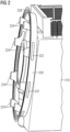
- FIG. 2 shows a partial view of a canopy 210 according to an exemplary embodiment of the present invention.
- the canopy 210 comprises an interface section formed as a relatively short tubular member 220 with outlets 222 in the tubular surface of the interface section 220.
- a short duct 224 is inserted in each outlet opening 222.
- the ducts 224 are formed to receive used cooling fluid, e.g. hot air, exhausted by the generator (not shown) in the axial direction eject the fluid through the corresponding outlet opening 222 in the radial direction.
- the interface section 220 also comprises a flange or lip 228 configured to engage with a corresponding structure in the generator.
- outlets 222 and corresponding ducts 224 are arranged around the circumference of the tubular member 220.
- any number of outlets 222 such as one, two, three, four, six, 12 or 16 outlets 222, may be feasible and used in other embodiments of the present invention.
- FIG 3 shows the set of ducts 224 used in the exemplary embodiment shown in Figure 2 .
- each duct 224 comprises an inlet opening 225 pointing in the axial direction of the wind turbine and thereby configured to receive cooling fluid from the generator (not shown).
- each duct 224 comprises a bent duct portion 226 shaped to change the flow direction of the exhaust cooling fluid from the axial to a radial direction corresponding to the orientation of the duct outlet 227 which fits into the outlet opening 222 shown in Figure 2 .
- FIG 4 shows a partial view of the canopy 210 and a generator 450 according to the exemplary embodiment shown in Figure 2 .
- the generator 450 comprises a ventilation unit (fan or blower) 452 arranged to convey exhausted cooling fluid from inside the generator 450 to the duct 224 such that it can be ejected in the radial direction through the duct outlet 227.
- a ventilation unit fan or blower
- Figure 5 shows a first partial view of a canopy 510 according to a further exemplary embodiment of the present invention.
- This embodiment differs from the one discussed above in conjunction with Figure 2 to Figure 4 in the shape of the interface structure 530 which comprises radial protrusions 531 extending inwards towards the axis of the wind turbine in order to accommodate axial fluid outlets (not shown in Figure 5 but discussed further below in conjunction with Figure 6 ) that are in communication with ducts 532 providing the exhaust cooling fluid from the generator (not shown).
- Figure 6 shows a second partial view of the canopy 610 according to the further exemplary embodiment shown in Figure 5 .
- this second partial view one of the outlets 633 can be seen.
- the outlet 633 ends in a small pocket formed in the protrusion 531 (see Figure 5 ) and thus ejects the received cooling fluid in the axial direction.
- FIG 7 shows a partial view of canopy 710 and generator 750 according to the further exemplary embodiment shown in Figure 5 and Figure 6 .
- the generator 750 comprises a ventilation unit (fan or blower) 752 arranged to convey exhausted cooling fluid from inside the generator 750 to the duct 732 such that it can be ejected in the axial direction through the duct outlet 733 and into the pocket formed in the protrusion 731 before escaping to the surroundings of the wind turbine.
- a ventilation unit fan or blower
- FIG 8 shows a cross-sectional view of the generator 850 shown in Figure 7 .
- the generator 850 comprises a total of eight ventilation units 852 arranged close to the outer circumference of the generator 850 such that they can be connected to corresponding ducts (e.g., ducts 732 in Figure 7 ) which are in communication with corresponding outlets.
- ducts e.g., ducts 732 in Figure 7
- any other number of ventilation units 852 may be used in other exemplary embodiments, such as one, two, three, four, six, 12 or 16 ventilation units 852.
- both exemplary embodiments provide simple and compact structures for ejecting used generator cooling fluid through outlets formed in the interface section of the canopy. While the embodiment shown in Figure 2 to Figure 4 relies on a short tubular member adding a bit to the length of the canopy but without affecting the cross-section of the interface between canopy and generator, the embodiment shown in Figure 5 to Figure 8 avoids any axial extension by instead adding protrusions along the circumference of the interface section.
Landscapes
- Engineering & Computer Science (AREA)
- Life Sciences & Earth Sciences (AREA)
- Sustainable Energy (AREA)
- Sustainable Development (AREA)
- Combustion & Propulsion (AREA)
- Chemical & Material Sciences (AREA)
- Mechanical Engineering (AREA)
- General Engineering & Computer Science (AREA)
- Physics & Mathematics (AREA)
- Thermal Sciences (AREA)
- Power Engineering (AREA)
- Wind Motors (AREA)
- Motor Or Generator Cooling System (AREA)
Claims (10)
- Auvent (110, 210) pour une éolienne à entraînement direct, l'auvent comprenant une section d'interface (120, 220) configurée pour accoupler mécaniquement l'auvent à un générateur (150), dans lequel la section d'interface comprend au moins une sortie (122, 222) configurée pour recevoir du fluide de refroidissement évacué par le générateur et éjecter le fluide de refroidissement reçu, dans lequel la section d'interface comprend un organe tubulaire s'étendant dans la direction axiale de l'éolienne.
- Auvent selon la revendication précédente, dans lequel la section d'interface forme une forme circonférentielle autour d'une direction axiale de l'éolienne.
- Auvent selon l'une quelconque des revendications précédentes, dans lequel l'au moins une sortie est formée dans l'organe tubulaire et configurée pour éjecter le fluide de refroidissement reçu dans une direction radiale.
- Auvent (510, 610, 710) pour une éolienne à entraînement direct, l'auvent comprenant une section d'interface (530, 730) configurée pour accoupler mécaniquement l'auvent à un générateur (750), dans lequel la section d'interface comprend au moins une sortie (633, 733) configurée pour recevoir du fluide de refroidissement évacué par le générateur et éjecter le fluide de refroidissement reçu, dans lequel la section d'interface comprend au moins une saillie radiale (531, 731) dans laquelle l'au moins une sortie est formée, dans lequel une cavité est formée entre l'auvent et l'au moins une saillie radiale, et dans lequel l'au moins une sortie est configurée pour éjecter le fluide de refroidissement reçu à l'intérieur de la cavité.
- Auvent selon la revendication précédente, dans lequel l'au moins une sortie est configurée pour éjecter le fluide de refroidissement reçu dans la direction axiale.
- Auvent selon l'une quelconque des revendications précédentes, dans lequel l'au moins une sortie (122, 222, 633, 733) comprend une pluralité de sorties.
- Éolienne à entraînement direct comprenant un rotor (160), un générateur (150), et une nacelle agencée au niveau d'une extrémité supérieure d'une tour (170), dans laquelle la nacelle comprend un auvent (110, 210, 510, 610, 710) selon l'une quelconque des revendications précédentes.
- Éolienne selon la revendication précédente, dans laquelle le générateur comprend au moins une unité de ventilation (452, 752, 852) adaptée à évacuer le fluide de refroidissement vers l'au moins une sortie de l'auvent.
- Éolienne selon la revendication 7 ou la revendication 8, comprenant en outre au moins un conduit (224, 532, 632, 732) agencé pour guider le fluide de refroidissement évacué jusqu'à l'au moins une sortie.
- Éolienne selon l'une quelconque des revendications 7 à 9, dans laquelle le fluide de refroidissement est de l'air.
Priority Applications (3)
| Application Number | Priority Date | Filing Date | Title |
|---|---|---|---|
| EP21188121.4A EP4124752B1 (fr) | 2021-07-28 | 2021-07-28 | Auvent d'éolienne doté d'une sortie de fluide de refroidissement |
| US17/863,482 US12104579B2 (en) | 2021-07-28 | 2022-07-13 | Wind turbine canopy with cooling fluid outlet |
| CN202210898826.9A CN115681024B (zh) | 2021-07-28 | 2022-07-28 | 带有冷却流体出口的风力涡轮机罩盖 |
Applications Claiming Priority (1)
| Application Number | Priority Date | Filing Date | Title |
|---|---|---|---|
| EP21188121.4A EP4124752B1 (fr) | 2021-07-28 | 2021-07-28 | Auvent d'éolienne doté d'une sortie de fluide de refroidissement |
Publications (3)
| Publication Number | Publication Date |
|---|---|
| EP4124752A1 EP4124752A1 (fr) | 2023-02-01 |
| EP4124752C0 EP4124752C0 (fr) | 2025-04-30 |
| EP4124752B1 true EP4124752B1 (fr) | 2025-04-30 |
Family
ID=77103930
Family Applications (1)
| Application Number | Title | Priority Date | Filing Date |
|---|---|---|---|
| EP21188121.4A Active EP4124752B1 (fr) | 2021-07-28 | 2021-07-28 | Auvent d'éolienne doté d'une sortie de fluide de refroidissement |
Country Status (3)
| Country | Link |
|---|---|
| US (1) | US12104579B2 (fr) |
| EP (1) | EP4124752B1 (fr) |
| CN (1) | CN115681024B (fr) |
Family Cites Families (10)
| Publication number | Priority date | Publication date | Assignee | Title |
|---|---|---|---|---|
| US7427814B2 (en) * | 2006-03-22 | 2008-09-23 | General Electric Company | Wind turbine generators having wind assisted cooling systems and cooling methods |
| DE102008050848A1 (de) * | 2008-10-08 | 2010-04-15 | Wobben, Aloys | Ringgenerator |
| ITMI20110376A1 (it) * | 2011-03-10 | 2012-09-11 | Wilic Sarl | Aerogeneratore raffreddato a fluido |
| EP2587052A1 (fr) * | 2011-10-25 | 2013-05-01 | Ewt Ip B.V. | Eolienne avec un système de refroidissement |
| DK2806542T3 (en) * | 2013-05-22 | 2016-12-19 | Siemens Ag | Airflow Control Device |
| KR101521828B1 (ko) * | 2013-10-18 | 2015-05-20 | 대우조선해양 주식회사 | 풍력발전기 나셀의 냉각장치 |
| EP2902619B1 (fr) * | 2014-01-29 | 2018-01-17 | Siemens Aktiengesellschaft | Agencement de refroidissement pour une éolienne à entraînement direct |
| EP2958217B1 (fr) * | 2014-06-18 | 2018-01-31 | Siemens Aktiengesellschaft | Agencement de refroidissement du générateur |
| EP3270491A1 (fr) * | 2016-07-15 | 2018-01-17 | Siemens Aktiengesellschaft | Agencement de refroidissement de générateur de turbine éolienne |
| CN208057312U (zh) * | 2018-04-23 | 2018-11-06 | 北京金风科创风电设备有限公司 | 风力发电机组 |
-
2021
- 2021-07-28 EP EP21188121.4A patent/EP4124752B1/fr active Active
-
2022
- 2022-07-13 US US17/863,482 patent/US12104579B2/en active Active
- 2022-07-28 CN CN202210898826.9A patent/CN115681024B/zh active Active
Also Published As
| Publication number | Publication date |
|---|---|
| EP4124752A1 (fr) | 2023-02-01 |
| EP4124752C0 (fr) | 2025-04-30 |
| US12104579B2 (en) | 2024-10-01 |
| CN115681024B (zh) | 2026-01-23 |
| CN115681024A (zh) | 2023-02-03 |
| US20230036882A1 (en) | 2023-02-02 |
Similar Documents
| Publication | Publication Date | Title |
|---|---|---|
| EP2976829B1 (fr) | Agencement de commande d'écoulement d'air | |
| US6672070B2 (en) | Gas turbine with a compressor for air | |
| EP2357366B1 (fr) | Module d'echange de chaleur pour vehicule et vehicule le comportant | |
| US20180245598A1 (en) | Turbo Fan | |
| JPH0763199A (ja) | 軸流圧縮機から二次空気流を取り出す装置 | |
| US6994520B2 (en) | Internal core profile for a turbine nozzle airfoil | |
| EP3575609B1 (fr) | Système comportant une machine et un ventilateur | |
| US7374396B2 (en) | Bolt-on radial bleed manifold | |
| CN111092385A (zh) | 一种基于伯努利效应的主变压器室通风系统 | |
| EP4124752B1 (fr) | Auvent d'éolienne doté d'une sortie de fluide de refroidissement | |
| US20170353064A1 (en) | Cooling of an axial end region of a stator in a rotating electrical machine | |
| US6155777A (en) | Removal of cooling air on the housing side of a diffuser of a compressor stage of gas turbines | |
| WO2015147461A1 (fr) | Ventilateur centrifuge | |
| US8286430B2 (en) | Steam turbine two flow low pressure configuration | |
| CN109707574A (zh) | 具有包括水排放装置的机舱的风力涡轮机 | |
| EP4160002B1 (fr) | Éolienne avec déflecteur | |
| US20190145657A1 (en) | Blower assembly for use in an air handling system and method for assembling the same | |
| US11261871B2 (en) | Dual stage blower assembly | |
| CN210509722U (zh) | 风机组件及具有其的空调柜机 | |
| TWI812263B (zh) | 風機及清潔設備 | |
| EP3342991B1 (fr) | Déflecteurs pour le refroidissement dans une turbine à gaz | |
| CN210780410U (zh) | 风冷式电机 | |
| EP2623721B1 (fr) | Turbine à vapeur comportant un carter monocoque, un rotor à tambour et des anneaux de guidage individuels | |
| US6074181A (en) | Shroud for fan motor cooling | |
| CN222799255U (zh) | 一种出风组件、空调外机和空调器 |
Legal Events
| Date | Code | Title | Description |
|---|---|---|---|
| PUAI | Public reference made under article 153(3) epc to a published international application that has entered the european phase |
Free format text: ORIGINAL CODE: 0009012 |
|
| STAA | Information on the status of an ep patent application or granted ep patent |
Free format text: STATUS: THE APPLICATION HAS BEEN PUBLISHED |
|
| AK | Designated contracting states |
Kind code of ref document: A1 Designated state(s): AL AT BE BG CH CY CZ DE DK EE ES FI FR GB GR HR HU IE IS IT LI LT LU LV MC MK MT NL NO PL PT RO RS SE SI SK SM TR |
|
| STAA | Information on the status of an ep patent application or granted ep patent |
Free format text: STATUS: REQUEST FOR EXAMINATION WAS MADE |
|
| 17P | Request for examination filed |
Effective date: 20230801 |
|
| RBV | Designated contracting states (corrected) |
Designated state(s): AL AT BE BG CH CY CZ DE DK EE ES FI FR GB GR HR HU IE IS IT LI LT LU LV MC MK MT NL NO PL PT RO RS SE SI SK SM TR |
|
| GRAP | Despatch of communication of intention to grant a patent |
Free format text: ORIGINAL CODE: EPIDOSNIGR1 |
|
| STAA | Information on the status of an ep patent application or granted ep patent |
Free format text: STATUS: GRANT OF PATENT IS INTENDED |
|
| INTG | Intention to grant announced |
Effective date: 20241219 |
|
| GRAS | Grant fee paid |
Free format text: ORIGINAL CODE: EPIDOSNIGR3 |
|
| GRAA | (expected) grant |
Free format text: ORIGINAL CODE: 0009210 |
|
| STAA | Information on the status of an ep patent application or granted ep patent |
Free format text: STATUS: THE PATENT HAS BEEN GRANTED |
|
| AK | Designated contracting states |
Kind code of ref document: B1 Designated state(s): AL AT BE BG CH CY CZ DE DK EE ES FI FR GB GR HR HU IE IS IT LI LT LU LV MC MK MT NL NO PL PT RO RS SE SI SK SM TR |
|
| REG | Reference to a national code |
Ref country code: CH Ref legal event code: EP Ref country code: GB Ref legal event code: FG4D |
|
| REG | Reference to a national code |
Ref country code: IE Ref legal event code: FG4D |
|
| REG | Reference to a national code |
Ref country code: DE Ref legal event code: R096 Ref document number: 602021029895 Country of ref document: DE |
|
| U01 | Request for unitary effect filed |
Effective date: 20250520 |
|
| U07 | Unitary effect registered |
Designated state(s): AT BE BG DE DK EE FI FR IT LT LU LV MT NL PT RO SE SI Effective date: 20250528 |
|
| U20 | Renewal fee for the european patent with unitary effect paid |
Year of fee payment: 5 Effective date: 20250828 |
|
| PG25 | Lapsed in a contracting state [announced via postgrant information from national office to epo] |
Ref country code: ES Free format text: LAPSE BECAUSE OF FAILURE TO SUBMIT A TRANSLATION OF THE DESCRIPTION OR TO PAY THE FEE WITHIN THE PRESCRIBED TIME-LIMIT Effective date: 20250430 |
|
| PG25 | Lapsed in a contracting state [announced via postgrant information from national office to epo] |
Ref country code: GR Free format text: LAPSE BECAUSE OF FAILURE TO SUBMIT A TRANSLATION OF THE DESCRIPTION OR TO PAY THE FEE WITHIN THE PRESCRIBED TIME-LIMIT Effective date: 20250731 Ref country code: NO Free format text: LAPSE BECAUSE OF FAILURE TO SUBMIT A TRANSLATION OF THE DESCRIPTION OR TO PAY THE FEE WITHIN THE PRESCRIBED TIME-LIMIT Effective date: 20250730 |
|
| PG25 | Lapsed in a contracting state [announced via postgrant information from national office to epo] |
Ref country code: PL Free format text: LAPSE BECAUSE OF FAILURE TO SUBMIT A TRANSLATION OF THE DESCRIPTION OR TO PAY THE FEE WITHIN THE PRESCRIBED TIME-LIMIT Effective date: 20250430 |
|
| PGFP | Annual fee paid to national office [announced via postgrant information from national office to epo] |
Ref country code: GB Payment date: 20250722 Year of fee payment: 5 |
|
| PG25 | Lapsed in a contracting state [announced via postgrant information from national office to epo] |
Ref country code: HR Free format text: LAPSE BECAUSE OF FAILURE TO SUBMIT A TRANSLATION OF THE DESCRIPTION OR TO PAY THE FEE WITHIN THE PRESCRIBED TIME-LIMIT Effective date: 20250430 |
|
| PG25 | Lapsed in a contracting state [announced via postgrant information from national office to epo] |
Ref country code: RS Free format text: LAPSE BECAUSE OF FAILURE TO SUBMIT A TRANSLATION OF THE DESCRIPTION OR TO PAY THE FEE WITHIN THE PRESCRIBED TIME-LIMIT Effective date: 20250731 |
|
| PG25 | Lapsed in a contracting state [announced via postgrant information from national office to epo] |
Ref country code: IS Free format text: LAPSE BECAUSE OF FAILURE TO SUBMIT A TRANSLATION OF THE DESCRIPTION OR TO PAY THE FEE WITHIN THE PRESCRIBED TIME-LIMIT Effective date: 20250830 |
|
| PG25 | Lapsed in a contracting state [announced via postgrant information from national office to epo] |
Ref country code: SM Free format text: LAPSE BECAUSE OF FAILURE TO SUBMIT A TRANSLATION OF THE DESCRIPTION OR TO PAY THE FEE WITHIN THE PRESCRIBED TIME-LIMIT Effective date: 20250430 |
|
| PG25 | Lapsed in a contracting state [announced via postgrant information from national office to epo] |
Ref country code: CZ Free format text: LAPSE BECAUSE OF FAILURE TO SUBMIT A TRANSLATION OF THE DESCRIPTION OR TO PAY THE FEE WITHIN THE PRESCRIBED TIME-LIMIT Effective date: 20250430 |
|
| PG25 | Lapsed in a contracting state [announced via postgrant information from national office to epo] |
Ref country code: SK Free format text: LAPSE BECAUSE OF FAILURE TO SUBMIT A TRANSLATION OF THE DESCRIPTION OR TO PAY THE FEE WITHIN THE PRESCRIBED TIME-LIMIT Effective date: 20250430 |
|
| REG | Reference to a national code |
Ref country code: CH Ref legal event code: H13 Free format text: ST27 STATUS EVENT CODE: U-0-0-H10-H13 (AS PROVIDED BY THE NATIONAL OFFICE) Effective date: 20260224 |
|
| PLBE | No opposition filed within time limit |
Free format text: ORIGINAL CODE: 0009261 |
|
| STAA | Information on the status of an ep patent application or granted ep patent |
Free format text: STATUS: NO OPPOSITION FILED WITHIN TIME LIMIT |
|
| REG | Reference to a national code |
Ref country code: CH Ref legal event code: L10 Free format text: ST27 STATUS EVENT CODE: U-0-0-L10-L00 (AS PROVIDED BY THE NATIONAL OFFICE) Effective date: 20260311 |
|
| 26N | No opposition filed |
Effective date: 20260202 |
|
| PG25 | Lapsed in a contracting state [announced via postgrant information from national office to epo] |
Ref country code: CH Free format text: LAPSE BECAUSE OF NON-PAYMENT OF DUE FEES Effective date: 20250731 |