EP4125144A2 - Électrode, batterie au lithium contenant l'électrode et son procédé de préparation - Google Patents
Électrode, batterie au lithium contenant l'électrode et son procédé de préparation Download PDFInfo
- Publication number
- EP4125144A2 EP4125144A2 EP22187605.5A EP22187605A EP4125144A2 EP 4125144 A2 EP4125144 A2 EP 4125144A2 EP 22187605 A EP22187605 A EP 22187605A EP 4125144 A2 EP4125144 A2 EP 4125144A2
- Authority
- EP
- European Patent Office
- Prior art keywords
- electrode
- active material
- material layer
- electrode active
- current collector
- Prior art date
- Legal status (The legal status is an assumption and is not a legal conclusion. Google has not performed a legal analysis and makes no representation as to the accuracy of the status listed.)
- Pending
Links
Images






Classifications
-
- H—ELECTRICITY
- H01—ELECTRIC ELEMENTS
- H01M—PROCESSES OR MEANS, e.g. BATTERIES, FOR THE DIRECT CONVERSION OF CHEMICAL ENERGY INTO ELECTRICAL ENERGY
- H01M4/00—Electrodes
- H01M4/02—Electrodes composed of, or comprising, active material
- H01M4/13—Electrodes for accumulators with non-aqueous electrolyte, e.g. for lithium-accumulators; Processes of manufacture thereof
-
- H—ELECTRICITY
- H01—ELECTRIC ELEMENTS
- H01M—PROCESSES OR MEANS, e.g. BATTERIES, FOR THE DIRECT CONVERSION OF CHEMICAL ENERGY INTO ELECTRICAL ENERGY
- H01M10/00—Secondary cells; Manufacture thereof
- H01M10/05—Accumulators with non-aqueous electrolyte
- H01M10/052—Li-accumulators
-
- H—ELECTRICITY
- H01—ELECTRIC ELEMENTS
- H01M—PROCESSES OR MEANS, e.g. BATTERIES, FOR THE DIRECT CONVERSION OF CHEMICAL ENERGY INTO ELECTRICAL ENERGY
- H01M10/00—Secondary cells; Manufacture thereof
- H01M10/05—Accumulators with non-aqueous electrolyte
- H01M10/052—Li-accumulators
- H01M10/0525—Rocking-chair batteries, i.e. batteries with lithium insertion or intercalation in both electrodes; Lithium-ion batteries
-
- H—ELECTRICITY
- H01—ELECTRIC ELEMENTS
- H01M—PROCESSES OR MEANS, e.g. BATTERIES, FOR THE DIRECT CONVERSION OF CHEMICAL ENERGY INTO ELECTRICAL ENERGY
- H01M4/00—Electrodes
- H01M4/02—Electrodes composed of, or comprising, active material
- H01M4/04—Processes of manufacture in general
- H01M4/0402—Methods of deposition of the material
- H01M4/0404—Methods of deposition of the material by coating on electrode collectors
-
- H—ELECTRICITY
- H01—ELECTRIC ELEMENTS
- H01M—PROCESSES OR MEANS, e.g. BATTERIES, FOR THE DIRECT CONVERSION OF CHEMICAL ENERGY INTO ELECTRICAL ENERGY
- H01M4/00—Electrodes
- H01M4/02—Electrodes composed of, or comprising, active material
- H01M4/04—Processes of manufacture in general
- H01M4/0402—Methods of deposition of the material
- H01M4/0409—Methods of deposition of the material by a doctor blade method, slip-casting or roller coating
-
- H—ELECTRICITY
- H01—ELECTRIC ELEMENTS
- H01M—PROCESSES OR MEANS, e.g. BATTERIES, FOR THE DIRECT CONVERSION OF CHEMICAL ENERGY INTO ELECTRICAL ENERGY
- H01M4/00—Electrodes
- H01M4/02—Electrodes composed of, or comprising, active material
- H01M4/04—Processes of manufacture in general
- H01M4/043—Processes of manufacture in general involving compressing or compaction
- H01M4/0435—Rolling or calendering
-
- H—ELECTRICITY
- H01—ELECTRIC ELEMENTS
- H01M—PROCESSES OR MEANS, e.g. BATTERIES, FOR THE DIRECT CONVERSION OF CHEMICAL ENERGY INTO ELECTRICAL ENERGY
- H01M4/00—Electrodes
- H01M4/02—Electrodes composed of, or comprising, active material
- H01M4/04—Processes of manufacture in general
- H01M4/0438—Processes of manufacture in general by electrochemical processing
- H01M4/0469—Electroforming a self-supporting electrode; Electroforming of powdered electrode material
-
- H—ELECTRICITY
- H01—ELECTRIC ELEMENTS
- H01M—PROCESSES OR MEANS, e.g. BATTERIES, FOR THE DIRECT CONVERSION OF CHEMICAL ENERGY INTO ELECTRICAL ENERGY
- H01M4/00—Electrodes
- H01M4/02—Electrodes composed of, or comprising, active material
- H01M4/13—Electrodes for accumulators with non-aqueous electrolyte, e.g. for lithium-accumulators; Processes of manufacture thereof
- H01M4/139—Processes of manufacture
-
- H—ELECTRICITY
- H01—ELECTRIC ELEMENTS
- H01M—PROCESSES OR MEANS, e.g. BATTERIES, FOR THE DIRECT CONVERSION OF CHEMICAL ENERGY INTO ELECTRICAL ENERGY
- H01M4/00—Electrodes
- H01M4/02—Electrodes composed of, or comprising, active material
- H01M4/62—Selection of inactive substances as ingredients for active masses, e.g. binders, fillers
- H01M4/621—Binders
- H01M4/622—Binders being polymers
-
- H—ELECTRICITY
- H01—ELECTRIC ELEMENTS
- H01M—PROCESSES OR MEANS, e.g. BATTERIES, FOR THE DIRECT CONVERSION OF CHEMICAL ENERGY INTO ELECTRICAL ENERGY
- H01M4/00—Electrodes
- H01M4/02—Electrodes composed of, or comprising, active material
- H01M4/62—Selection of inactive substances as ingredients for active masses, e.g. binders, fillers
- H01M4/621—Binders
- H01M4/622—Binders being polymers
- H01M4/623—Binders being polymers fluorinated polymers
-
- H—ELECTRICITY
- H01—ELECTRIC ELEMENTS
- H01M—PROCESSES OR MEANS, e.g. BATTERIES, FOR THE DIRECT CONVERSION OF CHEMICAL ENERGY INTO ELECTRICAL ENERGY
- H01M4/00—Electrodes
- H01M4/02—Electrodes composed of, or comprising, active material
- H01M4/62—Selection of inactive substances as ingredients for active masses, e.g. binders, fillers
- H01M4/624—Electric conductive fillers
- H01M4/625—Carbon or graphite
-
- H—ELECTRICITY
- H01—ELECTRIC ELEMENTS
- H01M—PROCESSES OR MEANS, e.g. BATTERIES, FOR THE DIRECT CONVERSION OF CHEMICAL ENERGY INTO ELECTRICAL ENERGY
- H01M4/00—Electrodes
- H01M4/02—Electrodes composed of, or comprising, active material
- H01M4/64—Carriers or collectors
- H01M4/66—Selection of materials
- H01M4/661—Metal or alloys, e.g. alloy coatings
-
- H—ELECTRICITY
- H01—ELECTRIC ELEMENTS
- H01M—PROCESSES OR MEANS, e.g. BATTERIES, FOR THE DIRECT CONVERSION OF CHEMICAL ENERGY INTO ELECTRICAL ENERGY
- H01M4/00—Electrodes
- H01M4/02—Electrodes composed of, or comprising, active material
- H01M4/64—Carriers or collectors
- H01M4/66—Selection of materials
- H01M4/663—Selection of materials containing carbon or carbonaceous materials as conductive part, e.g. graphite, carbon fibres
-
- H—ELECTRICITY
- H01—ELECTRIC ELEMENTS
- H01M—PROCESSES OR MEANS, e.g. BATTERIES, FOR THE DIRECT CONVERSION OF CHEMICAL ENERGY INTO ELECTRICAL ENERGY
- H01M4/00—Electrodes
- H01M4/02—Electrodes composed of, or comprising, active material
- H01M4/64—Carriers or collectors
- H01M4/70—Carriers or collectors characterised by shape or form
-
- H—ELECTRICITY
- H01—ELECTRIC ELEMENTS
- H01M—PROCESSES OR MEANS, e.g. BATTERIES, FOR THE DIRECT CONVERSION OF CHEMICAL ENERGY INTO ELECTRICAL ENERGY
- H01M4/00—Electrodes
- H01M4/02—Electrodes composed of, or comprising, active material
- H01M2004/021—Physical characteristics, e.g. porosity, surface area
-
- H—ELECTRICITY
- H01—ELECTRIC ELEMENTS
- H01M—PROCESSES OR MEANS, e.g. BATTERIES, FOR THE DIRECT CONVERSION OF CHEMICAL ENERGY INTO ELECTRICAL ENERGY
- H01M2220/00—Batteries for particular applications
- H01M2220/20—Batteries in motive systems, e.g. vehicle, ship, plane
-
- Y—GENERAL TAGGING OF NEW TECHNOLOGICAL DEVELOPMENTS; GENERAL TAGGING OF CROSS-SECTIONAL TECHNOLOGIES SPANNING OVER SEVERAL SECTIONS OF THE IPC; TECHNICAL SUBJECTS COVERED BY FORMER USPC CROSS-REFERENCE ART COLLECTIONS [XRACs] AND DIGESTS
- Y02—TECHNOLOGIES OR APPLICATIONS FOR MITIGATION OR ADAPTATION AGAINST CLIMATE CHANGE
- Y02E—REDUCTION OF GREENHOUSE GAS [GHG] EMISSIONS, RELATED TO ENERGY GENERATION, TRANSMISSION OR DISTRIBUTION
- Y02E60/00—Enabling technologies; Technologies with a potential or indirect contribution to GHG emissions mitigation
- Y02E60/10—Energy storage using batteries
Definitions
- an electrode a lithium battery employing the same, and a method of preparing the same.
- lithium batteries As various devices are increasingly miniaturized and have higher performance, it has become important for lithium batteries to have higher energy density as well as miniaturization and weight reduction. That is, lithium batteries having high capacity have become increasingly important.
- lithium batteries with increased flexibility have become increasingly important.
- One aspect provides a novel electrode capable of preventing performance degradation in a battery by having uniform distribution of constituent components inside the electrode.
- a novel electrode capable of preventing performance degradation in a battery and increasing flexibility of the battery by including an electrode current collector positioned in a part of the electrode and including through-holes in an electrode active material layer.
- Another aspect provides a lithium battery comprising the electrode.
- Another aspect provides a preparation method of the electrode.
- an electrode including: an electrode active material layer containing an electrode active material and a binder; and an electrode current collector positioned in a portion of one side of, or in a portion between both sides of, the electrode active material layer, wherein the electrode active material layer includes a plurality of through-holes.
- a lithium battery including: a cathode; an anode; and an electrolyte disposed between the cathode and the anode, wherein at least one of the cathode and the anode is the electrode described above.
- an electrode preparation method including: preparing a mixture by dry mixing an electrode active material, a dry conductive material, and a dry binder; providing an electrode current collector; preparing an electrode including an electrode active material layer disposed on one side or both sides of the electrode current collector, by placing and rolling the mixture on the one side or both sides of the electrode current collector; and introducing a plurality of through-holes into the electrode active material layer, wherein the introduction of the plurality of through-holes is carried out at the same time as the rolling, or subsequent to the rolling.
- dry refers to a state that is deliberately not in contact with solvents, such as processing solvents, or a state that deliberately does not contain solvents.
- a dry electrode active material refers to an electrode active material that is deliberately not in contact with solvents, or an electrode active material that deliberately does not contain solvents.
- a dry conductive material refers to a conductive material that is deliberately not in contact with solvents, or a conductive material that deliberately does not contain solvents.
- a dry binder refers to a binder that is deliberately not in contact with solvents, or a binder that deliberately does not contain solvents.
- a binder that does not mix with solvents while remaining in a liquid state at room temperature is a dry binder.
- a length of an electrode, a thickness of an electrode, a diameter of through-holes, a depth of through-holes, and a surface area of through-holes refer to an average length of the electrode, an average thickness of the electrode, an average diameter of the through-holes, an average depth of the through-holes, and an average surface area of the through-holes, respectively.
- An average value is, for example, an arithmetic mean of values measured at a plurality of points.
- a length of an electrode, a thickness of an electrode, a diameter of through-holes, a depth of through-holes, and a surface area of through-holes may be each measured using a micrometer, or from a scanning electron microscopic image, or an optical microscopic image.
- the term "diameter" of a particle refers to an average diameter of the particle if the particle is spherical, and for a non-spherical particle, refers to an average major axis length of the particle.
- the diameter of a particle may be measured using a particle size analyzer (PSA).
- a "diameter" of a particle is, for example, an average diameter.
- the average diameter is, for example, a median particle diameter (D50).
- the median particle diameter (D50) refers to the size of particles corresponding to 50% cumulative volume in a distribution of particle sizes measured by a laser diffraction method, counted from the side of particles having the smallest particle size.
- An electrode according to an embodiment includes: an electrode active material layer containing an electrode active material and a binder; and an electrode current collector positioned in a portion on one side, or in a portion between both sides, of the electrode active material layer, wherein the electrode active material layer includes a plurality of through-holes.
- the electrode current collector As the electrode current collector is disposed in a portion on one side, or in a portion between both sides, of the electrode active material layer, the volume occupied by the electrode current collector in the electrode decreases. Accordingly, the energy density of a lithium battery including an electrode with such a decreased volume occupied by electrode current collector increases. Accordingly, a lithium battery providing an improved output can be provided.
- the electrode active material layer includes a plurality of through-holes
- high rate capability of the lithium battery is further improved.
- the electrolyte solution is disposed in a plurality of through-holes
- the contact area between the electrode and an electrolyte solution increases, and a conduction distance of lithium ions inside the electrode active material layer decreases.
- the plurality of through-holes function as ion conduction channels. Accordingly, by using the plurality of through-holes, an increase in internal resistance and degradation of high rate capability due to an imbalance of electrode reactions on the electrode surface and inside the electrode can be effectively suppressed.
- a high-density battery including an electrode with increased thickness and/or a laminated body thereof degradation in cycle characteristics at a high current density can be effectively prevented.
- a lithium battery employing an electrode including a plurality of through-holes internal resistance can be decreased, and degradation in high rate capability can be prevented.
- the electrode active material layer includes a plurality of through-holes
- flexibility of the lithium battery can be further improved. Accordingly, a lithium battery including an electrode with improved flexibility can be more suitable for use in shape-variable devices, such as wearable devices.
- the electrode may include: a first domain including the electrode active material layer, and the electrode current collector positioned on one side or between both sides of the electrode active material layer; and a second domain including the electrode active material layer, and free of the electrode current collector on the one side or between the both sides of the electrode active material layer.
- the second domain may include a plurality of through-holes, and the first domain may be free of through-holes.
- the contact area between the electrode active material layer and the electrode current collector increases as the first domain including the electrode current collector positioned on one side or between both sides of the electrode active material layer is free of through-holes, degradation in high rate capability caused by an electrical current concentrated on the electrode current collector during charging/discharging can be prevented, and adhesion between the electrode active material layer and the electrode current collector can be further improved.
- the electrode may be, for example, a stretchable electrode.
- the stretchable electrode may be stretchable in one or more directions selected between a length direction and a width direction of the stretchable electrode.
- the stretchable electrode may be stretched, for example, by 5 % or more, by 10 % or more, by 15 % or more, by 20 % or more, by 30 % or more, by 40 % or more, or by 50 % or more, in the length direction of the stretchable electrode.
- the stretchable electrode may be stretched, for example, by about 5 % to about 100%, by about 10% to about 100%, by about 15% to about 100%, by about 20% to about 100%, by about 30% to about 100%, by about 40% to about 100%, or by about 50% to about 100%, in the length direction of the electrode.
- the stretchable electrode may be stretched, for example, by 5% or more, by 10% or more, by 15% or more, by 20% or more, by 30% or more, by 40% or more, or by 50% or more, in the width direction of the electrode.
- the stretchable electrode may be stretched, for example, by about 5% to about 100%, by about 10% to about 100%, by about 15% to about 100%, by about 20% to about 100%, by about 30% to about 100%, by about 40% to about 100%, or by about 50% to about 100%, in the width direction of the electrode.
- the stretchable electrode for example, can be restored after stretching to an initial length without suffering cracks and the like within the electrode, and cracks and the like may not occur in the electrode even when subjected to such a cycle repeated multiple times.
- the stretchable electrode may contain an electrode current collector only in a first domain and may not contain an electrode current collector in a second domain, the second domain may be easily stretched.
- the electrode current collector is disposed only in a portion of the electrode, even when stacking a plurality of electrodes and then winding or bending the same, separation of electrode active material layers and electrode current collectors can be minimized, and lithium batteries of various forms can be easily implemented.
- One side of the electrode may include, for example, a surface A in which a plurality of through-holes are formed.
- the surface area of the surface A may be, for example, 99% or less, 90% or less, 50% or less, 40% or less, 30% or less, 20% or less, or 10% or less, of the entire surface area of the one side of the electrode.
- the surface area of the surface A may be, for example, about 0.1 % to about 99%, about 0.1 % to about 90%, about 0.1% to about 50%, about 0.1% to about 30%, about 0.2% to about 20%, about 0.2% to about 15%, about 0.2% to about 10%, or about 0.2% to about 5%, of the entire surface area of the one side of the electrode.
- the cycle characteristics of the lithium battery may be further enhanced.
- the surface A is a surface area of the surface of the electrode that the through-holes occupy.
- One side of the electrode may include, for example, a surface A in which a plurality of through-holes are formed, and a surface B formed of an electrode active material layer, and the surface area of the surface A may be smaller than the surface area of the surface B.
- the surface area of the surface A may be, for example, 99% or less, 90% or less, 50% or less, 40% or less, 30% or less, 20% or less, or 10% or less, of the surface area of the surface B.
- the surface area of the surface A may be, for example, about 0.1 % to about 99%, about 0.1% to about 90%, about 0.1% to about 50%, about 0.1% to about 30%, about 0.1% to about 20%, about 0.1% to about 15%, about 0.1% to about 10%, or about 0.1% to about 5%, of the surface area of the surface B.
- the surface area of the surface A, in which through-holes are formed has a value in the above ranges, the cycle characteristics of the lithium battery may be further enhanced.
- An average diameter (d1) of the plurality of through-holes may be, for example, about 0.1 ⁇ m to about 20 ⁇ m, about 0.1 ⁇ m to about 15 ⁇ m, about 0.1 ⁇ m to about 10 ⁇ m, about 0.1 ⁇ m to about 5 ⁇ m, or about 0.1 ⁇ m to about 1 ⁇ m.
- the plurality of through-holes may have an average diameter in the above ranges, the cycle characteristics of a lithium battery employing an electrode containing the plurality of the through-holes may be further enhanced.
- a ratio (d1/T1) of the average diameter (d1) of the plurality of through-holes to a thickness (T1) of the electrode active material layer may be about 0.001 to about 0.2, about 0.001 to about 0.15, about 0.001 to about 0.1, about 0.001 to about 0.05, or about 0.001 to about 0.01.
- the ratio (d1/T1) of the average thickness (d1) of the plurality of through-holes to the thickness (T1) of the electrode active material layer may have a value in the above ranges, the cycle characteristics of a lithium battery that employs an electrode containing the plurality of through-holes may be further enhanced.
- the plurality of through-holes included in the electrode may be positioned regularly with a uniform interval therebetween in the electrode active material layer.
- a regular current density distribution inside the electrode may be maintained. Accordingly, local degradations in the electrode active material layer caused by an irregular current distribution can be prevented, and consequently, degradations in cycle characteristics of a lithium battery can be prevented.
- the plurality of through-holes included in the electrode may be, for example, periodically disposed with a uniform interval therebetween in the electrode active material layer. As the plurality of through-holes may be periodically positioned in the electrode active material layer, a periodic current density distribution may be maintained inside the electrode. Accordingly, local degradations in the electrode active material layer caused by an aperiodic current distribution can be prevented, and consequently, degradations in cycle characteristics of a lithium battery can be prevented.
- the plurality of through-holes included in the electrode may be positioned, for example, two-dimensionally or three-dimensionally so as to have a lattice structure.
- the plurality of through-holes may be two-dimensionally or three-dimensionally positioned so as to have a lattice structure in the electrode active material layer included in the electrode, the cycle characteristics of a lithium battery including such an electrode may be further improved.
- An entrance (opening) of each of the through-holes included in the electrode may have, but is not limited to, at least one shape selected from among a circular shape, an oval shape, a triangular shape, a rectangular shape, a pentagonal shape, a hexagonal shape, an alphabet shape, and a donut shape, and may have any shape that is used in the relevant technical field and forms a through-hole.
- Examples of the alphabet shape may include at least one shape selected from the shapes of A to Z.
- Examples of the alphabet shape may include at least one shape selected from among an X shape, an H shape, a T shape, an L shape, and the like.
- the entrance of the through-hole may have, for example, a polyhedral shape.
- each of the through-holes may be determined from a scanning electron microscopic image or an optical microscopic image of a surface of the electrode.
- each of the through-holes included in the electrode may be positioned to pass through the electrode active material layer so as to form an angle of about 60 degrees to about 120 degrees, about 70 degrees to about 110 degrees, or about 80 degrees to about 100 degrees, with one side or both sides of the electrode active material layer.
- the through-holes may be positioned to form such an angle, the cycle characteristics of the lithium battery may be further improved.
- a cross-section of the electrode may include, for example, a structure in which the electrode active material layer and the through-holes are alternately aligned.
- a lithium battery including such an electrode may have further improved cycle characteristics.
- the electrode current collector may further include an interlayer disposed on one side or both sides of the electrode current collector.
- the material forming the electrode current collector may be a material that does not react with lithium i.e., any material that does not form an alloy or a compound with lithium and has conductivity.
- the metal substrate may be, for example, a metal or an alloy. Examples of the metal substrate include indium (In), copper (Cu), magnesium (Mg), stainless steel, titanium (Ti), iron (Fe), cobalt (Co), nickel (Ni), zinc (Zn), aluminium (Al), germanium (Ge), lithium (Li), or an alloy thereof.
- Examples of the electrode current collector may include at least one shape selected from among a sheet, a foil, a film, a plate, a porous body, a mesoporous body, a through-hole containing body, a polygonal ring body, a mesh body, a foam, and a non-woven body, but are not limited thereto and may be any shape used in the relevant technical field.
- the interlayer may be, for example, directly positioned on one side or both sides of the electrode current collector. As such, there may be no other layer positioned between the electrode current collector and the interlayer. As the interlayer may be directly positioned on one side or both sides of the electrode current collector, adhesion between the electrode current collector and the electrode active material layer may be further improved.
- a thickness of the interlayer may be, for example, 30% or less of a thickness of the electrode current collector.
- the thickness of the interlayer may be, for example, about 0.01 % to about 30 %, about 0.1 % to about 30 %, about 0.5 % to about 30 %, about 1 % to about 25 %, about 1 % to about 20 %, about 1 % to about 15 %, about 1 % to about 10 %, about 1 % to about 5 %, or about 1 % to about 3 %, of the thickness of the electrode current collector.
- the thickness of the interlayer may be, for example, about 10 nm to about 5 ⁇ m, about 50 nm to about 5 ⁇ m, about 200 nm to about 4 ⁇ m, about 500 nm to about 3 ⁇ m, about 500 nm to about 2 ⁇ m, about 500 nm to about 1.5 ⁇ m, or about 700 nm to about 1.3 ⁇ m.
- the interlayer may have a thickness in the above ranges, adhesion between the electrode current collector and the electrode active material layer may be further improved, and an increase in interfacial resistance may be suppressed.
- the interlayer may include, for example, a binder.
- a binder As the interlayer may include a binder, adhesion between the electrode current collector and the electrode active material layer may be further improved.
- the binder included in the interlayer may be, for example, a conductive binder or a non-conductive binder.
- Examples of the conductive binder include an ion-conducting binder and/or an electron-conducting binder.
- a binder having both ion conductivity and electron conductivity may belong to both the ion-conducting binder and the electron-conducting binder.
- the ion-conducting binder examples include polystyrene sulfonate (PSS), polyvinylidene fluoride-hexafluoropropylene (PVDF-HFP), polyvinyl fluoride (PVF), polyvinylidene fluoride (PVDF), poly(methyl methacrylate) (PMMA), polyethylene oxide (PEO), polyethylene glycol (PEG), polyacrylonitrile (PAN), polytetrafluoroethylene (PTFE), polyethylene dioxythiophene (PEDOT), polypyrrole (PPY), polyacrylonitrile (PAN), polyaniline, polyacetylene, and the like.
- the ion-conducting binder may contain a polar functional group.
- Examples of the ion-conducting binder containing a polar functional group include Nafion, Aquivion, Flemion, Gore, Aciplex, Morgane ADP, sulfonated poly(ether ether ketone) (SPEEK), sulfonated poly(arylene ether ketone ketone sulfone) (SPAEKKS), sulfonated poly(aryl ether ketone) (SPAEK), poly[bis(benzimidazobenzisoquinolinones)], (SPBIBI), poly(styrene sulfonate) (PSS), lithium 9,10-diphenylanthracene-2-sulfonate (DPASLi+), and the like.
- SPEEK sulfonated poly(ether ether ketone)
- SPAEKKS sulfonated poly(arylene ether ketone ketone sulfone)
- SPAEK sulfonated poly(
- the electron-conducting binder examples include polyacetylene, polythiophene, polypyrrole, poly(p-phenylene), poly(phenylenevinylene), poly(phenylenesulfide), polyaniline, and the like.
- the interlayer may be, for example, a conductive layer including a conductive polymer.
- the binder included in the interlayer may be selected from among binders included in the electrode active material layer, for example.
- the interlayer may include the same binder as the electrode active material layer.
- the binder included in the interlayer may be, for example, a fluorine-based binder.
- the fluorine-based binder included in the interlayer may be, for example, polyvinylidene fluoride (PVDF).
- PVDF polyvinylidene fluoride
- the interlayer may be positioned on the electrode current collector by, for example, a dry method or a wet method.
- the interlayer may be, for example, a tie layer containing a binder.
- the interlayer may include, for example, a carbon-based conductive material.
- the carbon-based conductive material included in the interlayer may be selected from among carbon-based conductive materials included in the electrode active material layer.
- the interlayer may include the same carbon-based conductive material as the electrode active material layer.
- the interlayer may include a carbon-based conductive material
- the interlayer may be, for example, a conductive layer.
- the interlayer may be, for example, a conductive layer containing a binder and a carbon-based conductive material.
- the interlayer may be disposed on the electrode current collector by, for example, a dry method such as deposition, e.g., CVD, PVD, and the like.
- the interlayer may be disposed on the electrode current collector by, for example, a wet method, such as spin coating, dip coating, and the like.
- the interlayer may be disposed on the electrode current collector by depositing a carbon-based conductive material on the electrode current collector by means of deposition.
- a dry-coated interlayer may be formed of a carbon-based conductive material and may not contain binders.
- the interlayer may be disposed on the electrode current collector by coating and drying a composition containing a carbon-based conductive material, a binder, and a solvent, on a surface of the electrode current collector.
- the interlayer may be a single-layer structure, or may be a multilayer structure including multiple layers.
- the electrode current collector may have a comparatively reduced thickness than an electrode current collector included in electrodes in the related art. Accordingly, an electrode according to an embodiment, by including a thin-film current collector for example, can be distinguished from electrodes in the related art that include a thick-film current collector. As the electrode according to an embodiment employs a thin-film current collector having a reduced thickness, the thickness of an electrode active material layer in the electrode including the thin-film current collector relatively increases. Consequently, a lithium battery employing such an electrode has an increased energy density.
- a thickness of the electrode current collector including a metal substrate and an interlayer may be, for example, less than 15 ⁇ m, 14.5 ⁇ m or less, or 14 ⁇ m or less.
- the thickness of the electrode current collector may be, for example, about 0.1 ⁇ m to less than about 15 ⁇ m, about 1 ⁇ m to about 14.5 ⁇ m, about 2 ⁇ m to about 14 ⁇ m, about 3 ⁇ m to about 14 ⁇ m, about 5 ⁇ m to about 14 ⁇ m, or about 10 ⁇ m to about 14 ⁇ m.
- the binder included in the electrode active material layer may be, for example, a dry binder.
- the dry binder is, for example, a binder that does not become impregnated, dissolved, nor dispersed in a solvent.
- the dry binder may be, for example, a binder that does not contain a solvent or is not in contact with a solvent.
- the dry binder may be, for example, a fibrillized binder.
- the fibrillized binder may serve as a matrix that supports and binds together an electrode active material and other components included in the electrode active material layer.
- the fibrillzed binder may be determined as having a fibrous form from, for example, a scanning electron microscopic image of a cross-section of the electrode.
- the fibrillized binder may have, for example, an aspect ratio of 10 or more, 20 or more, 50 or more, or 100 or more.
- dry binder examples include, but are not limited to, polytetrafluoroethylene (PTFE), a polyvinylidene fluoride-hexapropylene (PVDF-HFP) copolymer, a polyvinylidene fluoride (PVDF), a polyvinyl alcohol, polyacrylonitrile, carboxymethylcellulose (CMC), starch, hydroxypropyl cellulose, cellulose, polyvinylpyrrolidone, polyethylene, polypropylene, ethylene-propylene-diene polymer (EPDM), sulfonated-EPDM, styrene butadiene rubber (SBR), fluoro rubber, and copolymers thereof.
- PTFE polytetrafluoroethylene
- PVDF-HFP polyvinylidene fluoride-hexapropylene
- PVDF polyvinylidene fluoride
- a polyvinyl alcohol polyacrylonitrile
- CMC carboxymethylcellulose
- EPDM ethylene
- the dry binder may include, in particular, a fluorine-based binder.
- the fluorine-based binder may be, for example, polytetrafluoroethylene (PTFE), a polyvinylidene fluoride-hexapropylene (PVDF-HFP) copolymer, or polyvinylidene fluoride (PVDF).
- the amount of the dry binder included in the electrode active material layer may be, for example, about 1 wt% to about 10 wt%, or about 1 wt% to about 5 wt%, with respect to the total weight of the electrode active material layer.
- the electrode active material layer may include a dry binder in the above ranges, the electrode may have an improved adhesion and can maintain a high energy density.
- the electrode active material layer may further include, for example, a conductive material.
- the conductive material may be, for example, a dry conductive material.
- the dry conductive material may be, for example, a conductive material that does not become impregnated, dissolved nor dispersed in a solvent.
- the dry conductive material may be, for example, a conductive material that does not contain a solvent or is not in contact with a solvent.
- the dry conductive material may include, for example, a carbon-based conductive material.
- Examples of the carbon-based conductive material include, but are not limited to, carbon black, graphite particles, natural graphite, artificial graphite, acetylene black, Ketjen black, carbon fibers; carbon nanotubes; and the like, and any material used as a carbon-based conductive material in the relevant technical field may be used.
- the amount of the dry conductive material included in the electrode active material layer may be, for example, about 1 wt% to about 10 wt%, or about 1 wt% to about 5 wt%, with respect to the total weight of the electrode active material layer.
- the electrode active material layer may include a dry conductive material in the above ranges, the electrode may have improved conductivity and can maintain high energy density.
- the electrode active material layer may be, for example, a self-standing film.
- the electrode active material layer may retain the shape of a film without, for example, a support. Accordingly, the electrode active material layer may be prepared as a separate self-standing film and positioned on an electrode current collector.
- the electrode active material layer is prepared by a dry method and thus, contains no processing solvent deliberately added.
- the electrode active material layer may not contain any residual processing solvent. There may be a minute amount of solvent incidentally remaining in the electrode active material layer, but such a solvent would not be any processing solvent deliberately added. Accordingly, the electrode active material layer is distinguished from wet-type electrode active material layers that are prepared by mixing components with a processing solvent, and then partially or completely removing the processing solvent therefrom by drying.
- a rate of change in a vertical relative force (F VR ) as a function of depth, from a first point to a second point may be 300% or less, the first point being spaced apart by 5% in a direction of the electrode current collector from a surface of the electrode active material layer, and the second point being spaced apart by 5% from a surface of the electrode current collector, with respect to the total thickness of the electrode active material layer.
- F VR vertical relative force
- the rate of change in the vertical relative force may be, for example, about 10 % to about 300 %, about 10 % to about 250 %, about 10 % to about 200 %, about 10 % to about 150 %, or about 10 % to about 100 %.
- the second point, which is spaced apart by 5% in a direction of the electrode active material layer from the surface of electrode current collector, corresponds to, for example, a point that is spaced apart by 95% in a direction of the electrode current collector from the surface of the electrode active material layer, with respect to the total thickness of the electrode active material layer.
- the rate of change in vertical relative force may be 300% or less when measured by SAICAS (surface and interfacial measuring analysis system)
- uniformity of distribution of constituent components inside the electrode may be improved.
- an increase in internal resistance and side reactions caused by a non-uniform distribution of constituent components inside the electrode active material layer are suppressed, reversibility of electrode reactions may be improved.
- cycle characteristics of the lithium battery can be improved.
- adhesion force of the electrode active material layer and the electrode current collector can be further improved, and internal resistance of the electrode can be reduced. Accordingly, a lithium battery employing such an electrode may have improved cycle characteristics.
- a horizontal force ratio of a second horizontal force (F H2 ) at a second point to a first horizontal force (F H1 ) at a first point may be 50% or more, the first point being spaced apart by 10% in a direction of the electrode active material layer (for example, a depth direction) from the surface of the electrode current collector, and the second point being spaced apart by 10% in a direction of the electrode current collector from a surface of the electrode active material layer.
- the horizontal force ratio may be, for example, about 50 % to about 100 %, about 60 % to about 100 %, about 70 % to about 100 %, about 80 % to about 100 %, or about 90 % to about 100 %.
- the second point which is spaced apart by 10% in a direction of the electrode active material layer from the surface of the electrode current collector, corresponds to, for example, a point that is spaced apart by 90% in a direction of the electrode current collector from the surface of the electrode active material layer, with respect to the total thickness of the electrode active material layer.
- the horizontal force ratio is, for example, represented by Equation 2.
- the SAICAS measurement method is described in, for example, Evaluation Example 3.
- Horizontal Force Ratio Second Horizontal Force F H 2 / First Horizontal Force F H 1 ⁇ 100
- the horizontal force ratio may be 50% or more as measured by SAICAS, uniformity of distribution of constituent components inside the electrode can be further improved.
- the electrode has a horizontal relative force in the above range, a lithium battery employing such an electrode has further improved cycle characteristics.
- the electrode may be, for example, a cathode.
- the cathode includes a cathode active material layer, and the cathode active material layer includes a cathode active material.
- any lithium metal oxide that is commonly used in the relevant technical field may be used, without limitation.
- cathode active material examples include, for example, at least one of composite oxides of lithium and a metal selected from among cobalt, manganese, nickel, and a combination thereof.
- a compound represented by any one of the following chemical formulae may be used: Li a A 1-b B' b D 2 (In the formula, 0.90 ⁇ a ⁇ 1 and 0 ⁇ b ⁇ 0.5); Li a E 1-b B' b O 2-c D c (In the formula, 0.90 ⁇ a ⁇ 1, 0 ⁇ b ⁇ 0.5, and 0 ⁇ c ⁇ 0.05); LiE 2-b B' b O 4-c D c (In the formula, 0 ⁇ b ⁇ 0.5, and 0 ⁇ c ⁇ 0.05); Li a Ni 1-b-c Co b B' c D ⁇ (In the formula, 0.90 ⁇ a ⁇ 1, 0 ⁇ b ⁇ 0.5, 0 ⁇ c ⁇ 0.05, and
- a compound including a coating layer added on the surface of the above compound may also be used, and a mixture of the above compound and another compound with a coating layer added thereon may also be used.
- the coating layer added on the surface of the above compound may include, for example, compounds of a coated element, such as an oxide and a hydroxide of the coated element, an oxyhydroxide of the coated element, an oxycarbonate of the coated element, and a hydroxycarbonate of the coated element.
- a compound forming such a coating layer may be amorphous or crystalline.
- the coated element included in the coating layer may be Mg, Al, Co, K, Na, Ca, Si, Ti, V, Sn, Ge, Ga, B, As, Zr, or a mixture thereof.
- the method of forming the coating layer is selected from methods that do not adversely affect physical properties of the cathode active material.
- the coating method may be, for example, a spray coating method, a dipping method, or the like. Such specific coating methods are well-understood by those of ordinary skill in the art in the relevant technical field, and as such will not be further described in detail.
- the amount of a cathode active material included in the cathode active material layer may be, for example, from about 80 wt% to about 98 wt%, or from about 90 wt% to about 98 wt%, with respect to the total weight of the cathode active material layer.
- the cathode active material may be, for example, a composite cathode active material.
- the composite cathode active material may include, for example: a core containing a lithium transition metal oxide; and a shell disposed along a surface of the core, wherein the shell includes: at least one first metal oxide represented by chemical formula MaOb (0 ⁇ a ⁇ 3, 0 ⁇ b ⁇ 4, and if a is 1, 2, or 3, b is not an integer); and carbonaceous material (e.g., graphene), wherein the first metal oxide is disposed within a graphene matrix, M is at least one metal selected from Group 2 to Group 13, and Group 15 and Group 16 in the periodic table, the lithium transition metal oxide contains nickel, and a nickel content is 80 mol% or more with respect to the total number of moles of the transition metal.
- the shell containing the first metal oxide and carbonaceous material e.g., graphene
- the composite cathode active material owing to the use of a composite containing a plurality of first metal oxides disposed in the graphene matrix, allows the shell to be evenly disposed on the core while preventing aggregation of graphene. Accordingly, by effectively preventing the contact between the core and an electrolyte, side reactions from the contact between the core and the electrolyte can be prevented.
- the formation of resistant layers, such as NiO phase can be suppressed.
- elution of nickel ions can also be suppressed.
- the shell containing carbonaceous material such as graphene has flexibility, changes in volume of the composite cathode active material during charging/discharging can be easily accommodated, thus suppressing crack formation in the composite cathode active material. Since graphene has high electron conductivity, interfacial resistance between the composite cathode active material and an electrolyte solution decreases. Accordingly, despite the introduction of the shell containing graphene, internal resistance in the lithium battery may remain the same, or decrease. In addition, since the first metal oxide has voltage resistance (i.e., high withstand voltage), degradation of the lithium transition metal oxide included in the core during charging/discharging at a high voltage may be prevented.
- voltage resistance i.e., high withstand voltage
- a lithium battery including the composite cathode active material may have improved cycle characteristics and high-temperature stability.
- the shell may include, for example, a first metal oxide of one kind, or first metal oxides of two or more kinds that are different from each another.
- the lithium transition metal oxide in the composite cathode active material has a high nickel content of 80 mol% or more with respect to the total number of moles of the transition metal, as the shell containing the first metal oxide and carbonaceous material such as graphene is disposed on the core, both high discharge capacity and cycle characteristics can be provided.
- the composite cathode active material having a high nickel content of 80 mol% or more can provide excellent lifetime characteristics as well as a capacity improved over a composite cathode active material with a relatively low nickel content.
- the metal included in the first metal oxide may be, for example, at least one selected from among Al, Nb, Mg, Sc, Ti, Zr, V, W, Mn, Fe, Co, Pd, Cu, Ag, Zn, Sb, and Se.
- the first metal oxide may be, for example, at least one selected from among Al 2 O z (0 ⁇ z ⁇ 3), NbO x (0 ⁇ x ⁇ 2.5), MgO x (0 ⁇ x ⁇ 1), Sc 2 O z (0 ⁇ z ⁇ 3), TiO y (0 ⁇ y ⁇ 2), ZrO y (0 ⁇ y ⁇ 2), V 2 O z (0 ⁇ z ⁇ 3), WO y (0 ⁇ y ⁇ 2), MnO y (0 ⁇ y ⁇ 2), Fe 2 O z (0 ⁇ z ⁇ 3), Co 3 O w (0 ⁇ w ⁇ 4), PdO x (0 ⁇ x ⁇ 1), CuO x (0 ⁇ x ⁇ 1), AgO x (0 ⁇ x ⁇ 1), ZnO x (0 ⁇ x ⁇ 1), Sb 2 O z (0 ⁇ z ⁇ 3), and SeO y (0 ⁇ y ⁇ 2).
- the shell may include Al 2 O x (0 ⁇ x ⁇ 3) as a first metal oxide.
- the shell may further include a second metal oxide of one or more kinds, represented by M a O c (0 ⁇ a ⁇ 3, 0 ⁇ c ⁇ 4, and if a is 1, 2, or 3, c is an integer).
- M is at least one metal selected from Group 2 to Group 13, and Group 15 and Group 16 in the periodic table.
- the second metal oxide may include the same metal as the first metal oxide, and c/a, which is the ratio of c to a in the second metal oxide, may have a value greater than b/a, which is the ratio of b to a in the first metal oxide. For example, c/a > b/a.
- the second metal oxide may be selected from among, for example, Al 2 O 3 , NbO, NbO 2 , Nb 2 O 5 , MgO, Sc 2 O 3 , TiO 2 , ZrO 2 , V 2 O 3 , WO 2 , MnO 2 , Fe 2 O 3 , Co 3 O 4 , PdO, CuO, AgO, ZnO, Sb 2 O 3 , and SeO 2 .
- the first metal oxide may be a reduction product of the second metal oxide.
- the first metal oxide may be obtained from the reduction of a portion, or all, of the second metal oxide. As a result, the first metal oxide has a lower oxygen content and a higher metal oxidation number compared to the second metal oxide.
- the shell may include a first metal oxide, Al 2 O x (0 ⁇ x ⁇ 3), and a second metal oxide, Al 2 O 3 .
- graphene included in the shell and a transition metal of a lithium transition metal oxide included in the core may be chemically bound together through a chemical bond.
- the carbon atom (C) of graphene included in the shell, and a transition metal (Me) of the lithium transition metal oxide may be chemically bound together, for example, via an oxygen atom as in a C-O-Me bond.
- the core and the shell form a complex.
- the complex is distinguished from a simple physical mixture of graphene and the lithium transition metal oxide.
- graphene and the first metal oxide included the shell also, may be chemically bound to each other through a chemical bond.
- the chemical bond may be, for example, a covalent bond or an ionic bond.
- the covalent bond may be a bond that includes, for example, at least one from among an ester group, an ether group, a carbonyl group, an amide group, a carbonate anhydride group, and an acid anhydride group.
- the ionic bond may be a bond that includes, for example, a carboxylic acid ion, an ammonium ion, an acyl cation group, and the like.
- a thickness of the shell may be, for example, from about 1 nm to about 5 ⁇ m, from about 1 nm to about 1 ⁇ m, from about 1 nm to about 500 nm, from about 1 nm to about 200 nm, from about 1 nm to about 100 nm, from about 1 nm to about 90 nm, from about 1 nm to about 80 nm, from about 1 nm to about 70 nm, from about 1 nm to about 60 nm, from about 1 nm to about 50 nm, from about 1 nm to about 40 nm, from about 1 nm to about 30 nm, from about 1 nm to about 20 nm, or from about 1 nm to about 10 nm.
- the shell may have a thickness in the above ranges, an increase in internal resistance of a lithium battery including the composite cathode active material is suppressed.
- the amount of the complex included in the composite cathode active material may be 3 wt% or less, 2 wt% or less, 1 wt% or less, 0.5 wt% or less, or 0.2 wt% or less, with respect to the total weight of the composite cathode active material.
- the amount of the complex may be about 0.01 wt% to about 3 wt%, about 0.01 wt% to about 1 wt%, about 0.01 wt% to about 0.7 wt%, about 0.01 wt% to about 0.6 wt%, about 0.1 wt% to about 0.5 wt%, about 0.01 wt% to about 0.2 wt%, about 0.01 wt% to about 0.1 wt%, or about 0.03 wt% to about 0.07 wt%, with respect to the total weight of the composite cathode active material.
- the composite cathode active material may include the complex in the above ranges, a lithium battery including the composite cathode active material may have further improved cycle characteristics.
- At least one of the first metal oxide and the second metal oxide included in the complex may have an average diameter of about 1 nm to about 1 ⁇ m, about 1 nm to about 500 nm, about 1 nm to about 200 nm, about 1 nm to about 100 nm, about 1 nm to about 70 nm, about 1 nm to about 50 nm, about 1 nm to about 30 nm, about 3 nm to about 30 nm, about 3 nm to about 25 nm, about 5 nm to about 25 nm, about 5 nm to about 20 nm, or about 7 nm to about 20 nm.
- the complex can be more uniformly distributed within the graphene matrix. As a result, such a complex can be uniformly coated on the core without aggregation, thereby forming a shell.
- the first metal oxide and/or the second metal oxide may have a diameter in the above ranges, the first metal oxide and/or the second metal oxide may be more uniformly disposed on the core. As a result, as the first metal oxide and/or the second metal oxide are uniformly disposed on the core, withstand voltage characteristics can be more effectively realized.
- An average diameter of the first metal oxide and the second metal oxide may be measured by, for example, a measurement apparatus using a laser diffraction method, or a dynamic light scattering method.
- the average diameter may be measured by, for example, a laser scattering particle size distribution analyzer (for example, LA-920 manufactured by HORIBA), and is a volume-based median particle diameter (D50) at a cumulative percentage of 50% from the smallest particle size.
- the core included in the composite cathode active material may include, for example, a lithium transition metal oxide represented by Formula 1 below.
- a lithium transition metal oxide represented by Formula 1 Li a Ni x Co y M z O 2-b A b
- M is at least one selected from the group consisting of manganese (Mn), niobium (Nb), vanadium (V), magnesium (Mg), gallium (Ga), silicon (Si), tungsten (W), molybdenum (Mo), iron (Fe), chromium (Cr), copper (Cu), zinc (Zn), titanium (Ti), aluminium (Al), and boron (B), and A is F, S, CI, Br, or a combination thereof.
- M is at least one selected from the group consisting of manganese (Mn), niobium (Nb), vanadium (V), magnesium (Mg), gallium (Ga), silicon (Si), tungsten (W), molybdenum (Mo), iron (Fe), chromium (Cr), copper (Cu), zinc (Zn), titanium (Ti), aluminium (Al), and boron (B), and A is F, S, CI, Br, or a combination thereof.
- the core included in the composite cathode active material may include, for example, a lithium transition metal oxide represented by Formulae 2 to 5 below.
- a lithium transition metal oxide represented by Formulae 2 to 5 below.
- M is at least one selected from the group consisting of manganese (Mn), niobium (Nb), vanadium (V), magnesium (Mg), gallium (Ga), silicon (Si), tungsten (W), molybdenum (Mo), iron (Fe), chromium (Cr), copper (Cu), zinc (Zn), titanium (Ti), aluminium (Al), and boron (B), and A is F, S, CI, Br, or a combination thereof.
- M is at least one selected from the group consisting of manganese (Mn), niobium (Nb), vanadium (V), magnesium (Mg), gallium (Ga), silicon (Si), tungsten (W), molybdenum (Mo), iron (Fe), chromium (Cr), copper (Cu), zinc (Zn), titanium (Ti), aluminium (Al), and boron (B), and A is F, S, CI, Br, or a combination thereof.
- the electrode may be, for example, an anode.
- the anode includes an anode active material layer, and the anode active material layer includes an anode active material.
- the anode active material may be any anode active material that is used for a lithium battery in the relevant technical field.
- the anode active material includes one or more selected from the group consisting of lithium metal, a metal that can be alloyed with lithium, a transition metal oxide, a non-transition metal oxide, and a carbon-based material.
- Examples of the metal that can be alloyed with lithium may include Si, Sn, Al, Ge, Pb, Bi, Sb Si-Y alloys (Here, Y is an alkali metal, an alkali earth metal, a Group 13 element, a Group 14 element, a transition metal, a rare-earth element, or a combination of the aforementioned elements, and is not Si), a Sn-Y alloy (Here, Y is an alkali metal, an alkali earth metal, a Group 13 element, a Group 14 element, a transition metal, a rare-earth element, or a combination of the aforementioned elements, and is not Sn), and the like.
- Element Y is, for example, Mg, Ca, Sr, Ba, Ra, Sc, Y, Ti, Zr, Hf, Rf, V, Nb, Ta, Db, Cr, Mo, W, Sg, Tc, Re, Bh, Fe, Pb, Ru, Os, Hs, Rh, Ir, Pd, Pt, Cu, Ag, Au, Zn, Cd, B, Al, Ga, Sn, In, Ti, Ge, P, As, Sb, Bi, S, Se, Te, Po, or a combination thereof.
- the transition metal oxides are, for example, lithium titanium oxides, vanadium oxides, lithium vanadium oxides, and the like.
- the non-transition metal oxides are, for example, SnO 2 , SiO x (0 ⁇ x ⁇ 2), and the like.
- the carbon-based materials are, for example, a crystalline carbon, an amorphous carbon, or a mixture thereof.
- the crystalline carbon is, for example, graphite such as artificial graphite or natural graphite that is sheet type, flake type, spherical, or fibrous type.
- the amorphous carbon is, for example, soft carbon (low-temperature sintered carbon) or hard carbon, meso-phase pitch carbides, sintered cokes, and the like.
- the amount of anode active material included in the anode active material layer is, for example, from about 80 wt% to about 98 wt%, or from about 90 wt% to about 98 wt%, with respect to the total weight of the anode active material layer.
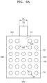
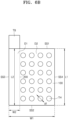
- an electrode (300) includes: an electrode active material layer (100) containing an electrode active material and a binder; and an electrode current collector (200) disposed on a portion of one side of the electrode active material layer (100), wherein the electrode active material layer (100) includes a plurality of through-holes (TH).
- a first domain (D1) is a domain that includes the electrode active material layer (100) and the electrode current collector (200) disposed on one side of the electrode active material layer (100). That is, the first domain (D1) is a domain that includes the electrode current collector (200) and the electrode active material layer (100) disposed in a thickness direction of the electrode on one side of the electrode current collector.
- a second domain (D2) is a domain that includes the electrode active material layer (100) and is free of the electrode current collector (200) disposed on one side of the electrode active material layer (100). That is, the second domain (D2) is the remaining area of the electrode active material layer that does not include the first domain (D1).
- the demarcation between the first domain (D1) and the second domain (D2) may be, for example, made by a virtual dotted line disposed along an electrode thickness direction.
- the second domain (D2) includes a plurality of through-holes (TH) having an arbitrary diameter (d1).
- the first domain (D1) and the second domain (D2) that the electrode (300) includes have substantially the same thickness (T1).
- the second domain (D2) includes a plurality of through-holes, and an electrolyte, that is, lithium ions, is transferred through the plurality of through-holes. Accordingly, the second domain (D2) is a domain that includes ion conduction channels. Accordingly, the electrode (300) including the second domain (D2) is an electrode that includes ion conduction channels.
- an electrode (300) includes: an electrode active material layer (100) containing an electrode active material and a binder; and an electrode current collector (200) disposed on a portion between both sides of the electrode active material layer (100), wherein the electrode active material layer (100) includes a plurality of through-holes (TH).
- a first domain (D1) is a domain that includes the electrode active material layer (100) and the electrode current collector (200) disposed between both sides of the electrode active material layer (100). That is, the first domain (D1) is a domain that includes the electrode current collector (200) and the electrode active material layer (100) disposed in an electrode thickness direction on both sides of the electrode current collector.
- the second domain (D2) is a domain that includes the electrode active material layer (100) and is free of the electrode current collector (200) disposed between both sides of the electrode active material layer (100). That is, the second domain (D2) is the remaining area of the electrode active material layer that does not include the first domain (D1).
- the demarcation between the first domain (D1) and the second domain (D2) may be, for example, made by a virtual dotted line disposed along the electrode thickness direction.
- the second domain (D2) includes a plurality of through-holes (TH) having an arbitrary diameter (d1).
- the first domain (D1) and the second domain (D2) that the electrode (300) includes have substantially the same thickness (T1).
- an electrode (300) includes: an electrode active material layer (100) including an electrode active material and a binder; an electrode current collector (200) disposed on a portion of one side of the electrode active material layer (100); and an interlayer (250) disposed between the electrode active material layer (100) and the electrode current collector (200).
- the electrode in FIG. 2A except that it further includes the interlayer (250), has the same features as the electrode in FIG. 1A .
- an electrode (300) includes: an electrode active material layer (100) including an electrode active material and a binder; an electrode current collector (200) disposed on a portion between both sides of the electrode active material layer (100); and a coating layer (250) disposed between the electrode active material layer (100) and the electrode current collector (200).
- the electrode in FIG. 2B except that it further includes the coating layer (250), has the same features as the electrode in FIG. 2A .
- an electrode (300) in the related art includes: an electrode active material layer (100) including an electrode active material and a binder; and an electrode current collector (200) that is disposed between both sides of the electrode active material layer (100) and has the same shape and surface area as the electrode active material layer (100).
- a first domain (D1) is a domain that includes the electrode active material layer (100) and the electrode current collector (200) disposed between both sides of the electrode active material layer (100). That is, the first domain (D1) is a domain that includes the electrode current collector (200) and the electrode active material layer (100) disposed in a thickness direction of the electrode on both sides of the electrode current collector.
- the electrode (300) in the related art is free of the second domain in which the electrode current collector (200) is not disposed on one side of the electrode active material layer (100).
- the electrode (300) in the related art does not include through-holes.
- a first domain (D1) that the electrode (300) in the related art includes has an arbitrary thickness (T1).
- an electrode (300) in the related art includes: an electrode active material layer (100) including an electrode active material and a binder; and an electrode current collector (200) disposed in a portion between both sides of the electrode active material layer (100).
- a first domain (D1) is a domain that includes the electrode active material layer (100) and the electrode current collector (200) disposed between both sides of the electrode active material layer (100). That is, the first domain (D1) is a domain that includes the electrode current collector (200) and the electrode active material layer (100) disposed in an electrode thickness direction on both sides of the electrode current collector.
- the second domain (D2) is a domain that includes the electrode active material layer (100) and is free of the electrode current collector (200) disposed between both sides of the electrode active material layer (100). That is, the second domain (D2) is the remaining domain of the electrode active material layer, except the first domain (D1).
- the demarcation between the first domain (D1) and the second domain (D2) may be, for example, made by a virtual dotted line disposed along an electrode thickness direction.
- the electrode (300) in the related art does not include through-holes.
- a first domain (D1) that the electrode (300) in the related art includes has an arbitrary thickness (T1).
- an electrode (300) in the related art includes: an electrode active material layer (100) including an electrode active material and a binder; and an electrode current collector (200) that is disposed between both sides of the electrode active material layer (100) and has the same shape and surface area as the electrode active material layer (100), wherein the electrode active material layer (100) includes a plurality of through-holes.
- a first domain (D1) is a domain that includes the electrode active material layer (100) and the electrode current collector (200) disposed between both sides of the electrode active material layer (100). That is, the first domain (D1) is a domain that includes the electrode current collector (200) and the electrode active material layer (100) disposed in an electrode thickness direction on both sides of the electrode current collector.
- the electrode (300) in the related art is free of the second domain in which the electrode current collector (200) is not disposed on one side of the electrode active material layer (100).
- the electrode (300) in the related art includes a plurality of through-holes (TH) that simultaneously pass through the electrode active material layer and the electrode current collector, and have an arbitrary diameter (d1).
- a first domain (D1) that the electrode (300) in the related art includes has an arbitrary thickness (T1).
- an electrode (300) includes: an electrode active material layer (100) including an electrode active material and a binder; and an electrode current collector (200) disposed on a portion between both sides of the electrode active material layer (100), wherein the electrode active material layer (100) includes a plurality of through-holes (TH).
- a first domain (D1) is a domain that includes the electrode active material layer (100) and the electrode current collector (200) positioned between both sides of the electrode active material layer (100). That is, the first domain (D1) is a domain that includes the electrode current collector (200) and the electrode active material layer (100) positioned in an electrode thickness direction on both sides of the electrode current collector.
- the second domain (D2) is a domain that includes the electrode active material layer (100) and is free of the electrode current collector (200) disposed between both sides of the electrode active material layer (100). That is, the second domain (D2) is the remaining domain of the electrode active material layer, except the first domain (D1).
- the second domain (D2) includes a plurality of through-holes (TH) having an arbitrary diameter (d1).
- the first domain (D1) and the second domain (D2) that the electrode (300) includes have substantially the same thickness (T1).
- a cross-section of FIG. 4 corresponds to FIG. 1B .
- an electrode active material layer (100) includes a first surface (S1) and a second surface (S2) opposing the first surface, includes a first side surface (SS1) connected at length-direction terminal ends of the first surface (S1) and the second surface (S2), and a second side surface (SS2) opposing the first side surface, and includes a third side surface (SS3) connected at width-direction terminal ends of the first surface (S1) and the second surface (S2), and a fourth side surface (SS4) opposing the third side surface.
- a first domain (D1) is a domain that is defined by the first surface (S1), the second surface (S2), the third side surface (SS3), and the fourth side surface (SS4), and includes an electrode current collector (200) disposed between the first surface (S1) and the second surface (S2).
- a second domain (D2) is a domain that is defined by the first surface (S1), the second surface (S2), the third side surface (SS3), and the fourth side surface (SS4), and is free of the electrode current collector (200) between the first surface (S1) and the second surface (S2).
- the second domain (D2) includes a plurality of through-holes (TH) having an arbitrary diameter (d1).
- the first domain (D1) and the second domain (D2) that the electrode (300) includes have substantially the same thickness (T1).
- an electrode active material layer (100) has a first surface area (A1) defined by a length direction first distance (L1) and a width direction first distance (W1), an electrode current collector (200) is disposed between a first surface (S1) and a second surface (S2), an electrode current collector (200) has a second surface area (A2) defined by a length direction second distance (L2) and a width direction second distance (W2), and the second surface area (A2) is 90% or less of the first surface area (A1) of the electrode active material layer (100).
- the second surface area (A2) of the electrode current collector (200) is from about 1% to about 90%, from about 5% to about 80%, from about 10% to about 70%, from about 10% to about 60%, from about 10% to about 50%, from about 10% to about 40%, from about 10% to about 30%, or from about 10% to about 20%, of the first surface area (A1) of the electrode active material layer (100).
- the electrode current collector (200) in the electrode (300) has a surface area that is less than the electrode active material layer (100)
- a lithium battery (1000) including the electrode (300) has a further improved energy density.
- the length direction second distance (L2) of the electrode current collector (200) is 90% or less, 80% or less, 70% or less, 60% or less, 50% or less, 40% or less, 30% or less, or 20% or less, of the length direction first distance (L1) of the electrode active material layer (100).
- the length direction second distance (L2) of the electrode current collector (200) is about 1% to about 90%, about 5% to about 80%, about 10% to about 70%, about 10% to about 60%, about 10% to about 50%, about 10% to about 40%, about 10% to about 30%, or about 10% to about 20%, of the length direction first distance (L1) of the electrode active material layer (100).
- the width direction second distance (W2) of the electrode current collector (200) is 100% or less, 90% or less, 80% or less, 70% or less, 60% or less, 50% or less, 40% or less, 30% or less, or 20% or less, of the width direction first distance (W1) of the electrode active material layer (100).
- the width direction second distance (W2) of the electrode current collector (200) is about 1% to about 100%, about 5% to about 90%, about 10% to about 80%, about 10% to about 70%, about 10% to about 60%, about 10% to about 50%, about 10% to about 40%, about 10% to about 30%, or about 10% to about 20%, of the width direction first distance (W1) of the electrode active material layer (100).
- the length direction second distance (L2) of the electrode current collector (200) is 90% or less, or 50% or less of the length direction first distance (L1) of the electrode active material layer (100), and the width direction second distance (W2) of the electrode current collector (200) is 90% or less, or 50% or less of the width direction first distance (W1) of the electrode active material layer (100).
- the electrode current collector (200) may have such a size, a lithium battery (1000) including the electrode (300) has a further improved energy density.
- the electrode current collector (200) is exposed on at least three side surfaces from among a first side surface (SS1), a second side surface (SS2), a third side surface (SS3) and a fourth side surface (SS4) that the electrode active material layer (100) includes.
- the electrode current collector (200) as it has a surface area smaller than the electrode active material layer (100), is exposed on a portion of side surfaces, for example, three, two, or one side surface included in the electrode active material layer (100).
- the number of side surfaces of the electrode active material layer (100) on which the electrode current collector (200) is exposed decreases, the likelihood of shorts caused through a side surface of the electrode active material layer (100) is reduced, thus improving reliability of the lithium battery (1000).
- the electrode current collector (200) further includes a tab (TB) extending out of the electrode active material layer (100) through at least two side surfaces selected from among the first side surface (SS1), the second side surface (SS2), the third side surface (SS3), and the fourth side surface (SS4).
- the tab (TB) extends out of the electrode active material layer (100) through the first side surface (SS1) and/or the second side surface (SS2).
- the tab (TB) extends out of the electrode active material layer (100) through the third side surface (SS3) and/or the fourth side surface (SS4).
- the tab (TB) extends out of the electrode active material layer (100) through one side surface, or two side surface opposing each other, shorts caused by multiple adjacent tabs (TB) can be prevented.
- the electrode current collector (200) disposed in a portion between both sides of the electrode active material layer (100) has various forms and can be disposed in various positions within the electrode active material layer (100).
- an electrode active material layer (100) defined by a first side surface (SS1), a second side surface (SS2), a third side surface (SS3), and a fourth side surface (SS4) in an electrode active material layer (100) defined by a first side surface (SS1), a second side surface (SS2), a third side surface (SS3), and a fourth side surface (SS4), the domain in which an electrode current collector (200) is disposed corresponds to a first domain, and the domain in which the electrode current collector (200) is not disposed corresponds to a second domain.
- the electrode active material layer (100) includes a plurality of through-holes (TH) having an arbitrary diameter (d1).
- a first domain (D1) is a domain that includes the electrode active material layer (100) and the electrode current collector (200) disposed on one side or between both sides of the electrode active material layer (100). That is, the first domain (D1) is a domain that includes the electrode current collector (200) and the electrode active material layer (100) disposed in an electrode thickness direction on one side or both sides of the electrode current collector.
- a second domain (D2) is a domain that includes the electrode active material layer (100) and is free of the electrode current collector (200) disposed on one side, or between both sides, of the electrode active material layer (100). That is, the second domain (D2) is the remaining domain of the electrode active material layer, except the first domain (D1).
- the electrode current collector (200) is disposed in a portion of the electrode active material layer (100) defined by the first side surface (SS1), the second side surface (SS2), the third side surface (SS3), and the fourth side surface (SS4).
- the electrode current collector (200) is exposed on the first side surface (SS1) of the electrode active material layer (100), and includes a tab (TB) extending out of the electrode active material layer (100) through the first side surface (SS1).
- a width direction distance (W T ) of the tab is 100% of a width direction second distance (W2) of the electrode current collector (200).
- the electrode current collector (200) is disposed in a portion of the electrode active material layer (100) defined by the first side surface (SS1), the second side surface (SS2), the third side surface (SS3), and the fourth side surface (SS4).
- the electrode current collector (200) is exposed on the first side surface (SS1), the second side surface (SS2), and the third side surface (SS3) of the electrode active material layer (100) and includes a tab (TB) extending out of the electrode active material layer (100) through the first side surface (SS1).
- a length direction second distance (L2) of the electrode current collector (200) is 100% of a length direction first distance (L1) of the electrode active material layer (100).
- the length direction second distance (L2) of the electrode current collector (200) is less than 100% of a width direction first distance (W1) of the electrode active material layer (100).
- the electrode current collector (200) is disposed in a portion of the electrode active material layer (100) defined by the first side surface (SS1), the second side surface (SS2), the third side surface (SS3), and the fourth side surface (SS4).
- the electrode current collector (200) is exposed on the first side surface (SS1), the second side surface (SS2), and the fourth side surface (SS4) of the electrode active material layer (100), and includes a tab (TB) extending out of the electrode active material layer (100) through the first side surface (SS1).
- the electrode current collector (200) is disposed in a portion of the electrode active material layer (100) defined by the first side surface (SS1), the second side surface (SS2), the third side surface (SS3), and the fourth side surface (SS4).
- the electrode current collector (200) is exposed on the first side surface (SS1) of the electrode active material layer (100), and includes a tab (TB) extending out of the electrode active material layer (100) through the first side surface (SS1).
- a width direction distance (W T ) of the tab is less than 100% of a width direction second distance (W2) of the electrode current collector (200).
- a plurality of electrode current collectors (200) are disposed in portions of an electrode active material layer (100) defined by a first side surface (SS1), a second side surface (SS2), a third side surface (SS3), and a fourth side surface (SS4).
- the plurality of electrode current collectors (200) spaced apart from one another along a length direction or width direction of the electrode active material layer (100) are included.
- the plurality of electrode current collectors (200) are, for example, evenly spaced apart from one another, or unevenly spaced apart from one another.
- the plurality of electrode current collectors (200) form 50 degrees or less, 40 degrees or less, 30 degrees or less, 25 degrees or less, 20 degrees or less, 15 degrees or less, 10 degrees or less, or 5 degrees or less, with one side of the electrode active material layer (100), for example, at least one of a first surface (S1) and a second surface (S2).
- the plurality of electrode current collectors (200) form 0 degrees with one side of the electrode active material layer (100), that is, are disposed parallel thereto.
- the plurality of electrode current collectors (200) are, for example, disposed between the first surface (S1) and the second surface (S2) of the electrode active material layer (100).
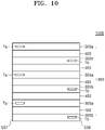
- an electrode active material layer (100) includes: a first domain (D1) in which an electrode current collector (200) is disposed between a first surface (S1) and a second surface (S2); and a second domain (D2) in which the electrode current collector (200) is not disposed between the first surface (S1) and the second surface (S2).
- the electrode current collector (200) includes a tab (TB).
- a lithium battery includes: a cathode; an anode; and an electrolyte disposed between the cathode and the anode, wherein at least one of the cathode and the anode is the electrode described above.
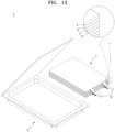
- a lithium battery (1000) includes: a cathode (300a); an anode (300b); and an electrolyte (400) disposed between the cathode (300a) and the anode (300b), wherein at least one of the cathode (300a) and the anode (300b) is the electrode described above.
- the lithium battery (1000) includes an electrode assembly (500).
- a second domain (D2) that the cathode (300a) and/or the anode (300b) include includes a plurality of through-holes (TH) having an arbitrary diameter (d1).
- a first domain (D1) does not include through-holes (TH).
- the electrode assembly (500) includes: a plurality of cathodes (300a) stacked in a thickness direction; a plurality of anodes (300b), each disposed between the plurality of cathodes (300a); and a plurality of electrolytes (400), each disposed between the plurality of cathodes (300a) and anodes (300b).
- the cathode (300a) includes a cathode current collector (200a), the cathode current collector (200a) includes a cathode tab (Ta) extending out of a cathode active material layer (100a) through one side surface (SS5) of the electrode assembly (500), the anode (300b) includes an anode current collector (200b), and the anode current collector (200b) includes an anode tab (Tb) extending out of an anode active material layer (100b) through the other side surface (SS6) opposing the one side surface (SS5) of the electrode assembly (500).
- a lithium battery (1000) includes the electrode assembly (500). Since the cathode tab (Ta) and the anode tab (Tb) are disposed on side surfaces opposing each other, the likelihood of shorts occurring between these two is reduced.
- the electrode assembly (500) includes: a plurality of cathodes (300a) stacked in a thickness direction; a plurality of anodes (300b), each disposed between the plurality of cathodes (300a); and a plurality of electrolytes (400), each disposed between the plurality of cathodes (300a) and anodes (300b).
- the cathode (300a) includes a cathode current collector (200a), the cathode current collector (200a) includes a cathode tab (Ta) extending out of a cathode active material layer (100a) through one side surface (SS5) of the electrode assembly (500), the anode (300b) includes an anode current collector (200b), and the anode current collector (200b) includes an anode tab (Tb) extending out of an anode active material layer (100b) through the same side surface (SS5) of the electrode assembly (500).
- a lithium battery (1000) includes the electrode assembly (500).
- FIG. 10 is a front view of one side surface (SS5) of FIG. 10 .
- a lithium battery (1000) includes an electrode assembly (500).
- a cathode tab (Ta) and an anode tab (Tb) are disposed on the same side surface, but since they are spaced apart from each other in a width direction, the likelihood of shorts occurring between these two is reduced.
- an electrode assembly comprising: a plurality of cathodes stacked in a thickness direction; a plurality of anodes, each disposed between the plurality of cathodes; and a plurality of electrolytes, each disposed between the plurality of cathodes and anodes, as one or more cathodes and/or anodes containing a plurality of through-holes are formed between cathodes and/or anodes not containing a plurality of through-holes, the cathodes and/or anodes containing the plurality of through-holes function as an ion conducting layer or an ion conducting channel of a sort, and thus, cycle characteristics, such as high rate capability, of a lithium battery including the electrode assembly can be improved.
- the lithium battery (1000) is, for example, a lithium ion battery, a lithium solid battery, a lithium air battery, or the like.
- the electrode preparation method includes: preparing a mixture by dry mixing an electrode active material, a dry conductive material, and a dry binder; providing an electrode current collector; preparing an electrode comprising an electrode active material layer disposed on one side or both sides of the electrode current collector, by placing and rolling the mixture on the one side or both sides of the electrode current collector; and introducing a plurality of through-holes into the electrode active material layer, wherein the introduction of the plurality of through-holes is carried out at the same time as the rolling, or subsequent to the rolling.
- An electrode prepared by the preparation method above has an improved uniformity of uniform adhesion distribution within the electrode, and thus, a lithium battery employing such an electrode has improved performance.
- a lithium battery employing such an electrode has improved cycle characteristics.
- a mixture is prepared by dry mixing an electrode active material, a dry conductive material, and a dry binder.
- the dry mixing refers to mixing in a state free of processing solvent.
- the processing solvent is, for example, a solvent used in manufacturing an electrode slurry.
- the processing solvent is, for example, water, NMP, or the like, but is not limited thereto, and may be any processing solvent that is used in manufacturing of electrode slurry.
- the dry mixing may be carried out using a mixer, and for example, at a temperature of about 25 °C to about 65 °C.
- the dry mixing may be carried out using a mixer, and for example, at a rotation rate of about 10 rpm to about 10,000 rpm, or about 100 rpm to about 10,000 rpm.
- the dry mixing may be carried out using a mixer, and for example, for about 1 minute to about 200 minutes, or about 1 minute to about 150 minutes.
- a first mixture may be prepared by first dry mixing of an electrode active material, a dry conductive material, and a dry binder.
- the first dry mixing may be carried out, for example, at a temperature of about 25 °C to about 65 °C, at a rotation rate of 2,000 rpm or less, and for a duration of 15 minutes or less.
- the first dry mixing may be carried out, for example, at a temperature of about 25 °C to about 65 °C, at a rotation rate of about 500 rpm to about 2,000 rpm, and for a duration of about 5 minutes to about 15 minutes.
- the electrode active material, the dry conductive material, and the dry binder may be uniformly mixed by the first dry mixing.
- a second mixture may be prepared by second dry mixing of an electrode active material, a dry conductive material, and a dry binder.
- the second dry mixing may be carried out, for example, at a temperature of about 25 °C to about 65 °C, at a rotation rate of 4,000 rpm or more, and for a duration of 10 minutes or more.
- the second dry mixing may be carried out, for example, at a temperature of about 25 °C to about 65 °C, at a rotation rate of about 4,000 rpm to about 9,000 rpm, and for a duration of about 10 minutes to about 60 minutes.
- a dry mixture including a fibrillated dry binder may be obtained.
- the mixer is, for example, a kneader.
- the mixer includes, for example: a chamber; at least one rotating shaft disposed and rotated inside the chamber; and a blade rotatably coupled to the rotating shaft and disposed in a length direction of the rotating shaft.
- the blade may be, for example, at least one selected from among a ribbon blade, a sigma blade, a Z blade, a dispersing blade, and a screw blade.
- the produced mixture may be introduced into an extruder apparatus and extruded into a sheet form.
- the pressure for extrusion is, for example, about 4 MPa to about 100 MPa, or about 10 MPa to about 90 MPa.
- the mixture thus obtained may be a sheet form. That is, the mixture thus obtained may be an electrode active material layer.
- the dry conductive material may include, but is not limited to: carbon black, graphite particles, natural graphite, artificial graphite, acetylene black, Ketjen black, and carbon fibers; carbon nanotubes; metal powder, metal fibers, or metal tubes of copper, nickel, aluminium, silver, and the like; and a conductive polymer such as a polyphenylene derivative. Any conductive material used in the relevant technical field may be used.
- the conductive material is, for example, a carbon-based conductive material. Further details on the dry conductive material are provided in the descriptions of the electrode above.
- the dry binder may be a vinylidene fluoride/hexafluoropropylene copolymer, polyvinylidene fluoride, polyacrylonitrile, polymethyl methacrylate, polytetrafluoroethylene (PTFE), a mixture of the aforementioned polymers, a styrene butadiene rubber-based polymer.
- PTFE polytetrafluoroethylene
- NMP N-methylpyrrolidone
- acetone water, or the like
- Any suitable material that is used in the relevant technical field may be used. Further details on the dry binder are provided in the descriptions of the electrode above.
- the amounts of the electrode active material, the dry conductive material, and the dry binder used in the electrode active material layer are as described in the description of the electrode above.
- a cathode utilizes a cathode active material as an electrode active material.
- the cathode active material is further described in the description of the electrode above.
- An anode utilizes an anode active material as an electrode active material.
- the anode active material is further described in the description of the electrode above.
- an electrode current collector is provided.
- the electrode current collector may further include an interlayer disposed on one side or both sides of the electrode current collector. Further details on the interlayer are provided in the descriptions of the electrode above.
- the preparation of the electrode current collector may further include, for example, placing an interlayer on one side or both sides of the electrode current collector.
- a cathode current collector is, for example, an aluminium foil.
- An anode current collector is, for example, a copper foil.
- the placement of a coating layer on one side or an upper side of the electrode current collector involves coating an interlayer on one side or both sides of the electrode current collector by a dry or wet coating method. Specific coating method is described in the description of the electrode current collector including an interlayer, provided above.
- an electrode comprising an electrode active material layer disposed on one side or both sides of the electrode current collector is prepared by placing and rolling the mixture on the one side or both sides of the electrode current collector.
- the rolling may be carried out by, for example, a press roll, a plate roll, or the like, but is not limited thereto.
- the pressure for the rolling is, for example, about 1.0 ton/cm to about 10.0 ton/cm. An excessively increasing pressure for the rolling may result in cracks in a thin film electrode current collector. Too low a pressure for the rolling may result in a low adhesion between the electrode current collector and the electrode active material layer.
- the introduction of a plurality of through-holes is carried out at the same time as the rolling, or subsequent to the rolling.
- a plurality of through-holes may be introduced into the electrode active material layer. As illustrated in FIGS. 1A to 2B , the plurality of through-holes may be formed in a second domain in which the electrode current collector is not disposed.
- the method of introducing the through-holes may be punching or the like, but is not limited thereto, and may be any method and/or device in the relevant technical field that are capable of introducing through-holes.
- the process of preparing the electrode having the electrode active material layer disposed on one side or both sides of the electrode current collector it is possible to introduce a plurality of through-holes into the electrode active material layer at the same time as rolling, by using a rolling roller including a plurality of bumps formed on a surface thereof.
- the plurality of through-holes may be formed in a second domain in which the electrode current collector is not disposed.
- the method of introducing through-holes into the electrode active material layer during an electrode preparation process is not limited to the use of a rolling roller including bumps formed on a surface thereof, and may be any method and/or device in the relevant technical field that are capable of introducing through-holes.
- a lithium battery is prepared by, for example, a method described below, but is not limited thereto, and may vary depending on the conditions required.
- one of a cathode and an anode, or both may be prepared according to the electrode preparation method described above.
- the other electrode may be prepared by a wet-type preparation method.
- the other electrode may be prepared by preparing an electrode slurry containing an electrode active material, a conductive material, a binder, and a solvent, and then coating and drying the prepared electrode slurry on an electrode current collector.
- the conductive material and the binder that an electrode prepared by a wet-type method includes may be selected from among conductive materials and binders used in the preparation of a dry-type electrode described above.
- the separator may be any one that is commonly used in lithium batteries.
- the separator may be one that has excellent electrolyte retention capability while having low resistance to migration of ions in an electrolyte.
- Examples of the separator include at least one of glass fiber, polyester, Teflon, polyethylene, polypropylene, and polytetrafluoroethylene (PTFE), or a combination thereof, each of which may be in the form of a non-woven or a woven fabric.
- PTFE polytetrafluoroethylene
- a windable separator including polyethylene, polypropylene, or the like may be used in a lithium ion battery, and a separator having excellent retention capability for an organic electrolyte solution may be used in a lithium-ion polymer battery.
- the separator may be prepared by a method provided below, but is not strictly limited to such a method, and may be adjusted depending on the conditions required.
- a polymer resin, a filler, and a solvent are combined to prepare a separator composition.
- the separator composition is directly coated on an electrode and then dried to form a separator.
- the separator composition may be cast on a support and dried, and then a separator film detached from the support may be laminated on an upper portion of the electrode, thereby forming a separator.
- the polymer used in preparing the separator is not particularly limited, and may be any polymer that is used as an adhesive material of electrode plates.
- the polymer include a vinylidenefluoride/hexafluoropropylene copolymer, polyvinylidenefluoride (PVDF), polyacrylonitrile, polymethylmethacrylate, or a mixture thereof, and the like.
- the electrolyte may be, for example, an organic electrolyte solution.
- the organic electrolyte solution may be prepared by, for example, dissolving a lithium salt in an organic solvent.
- any suitable organic solvent used in the relevant technical field may be used for the organic solvent.
- the organic solvent include propylene carbonate, ethylene carbonate, fluoroethylene carbonate, butylene carbonate, dimethyl carbonate, diethyl carbonate, methylethyl carbonate, methylpropyl carbonate, ethylpropyl carbonate, methylisopropyl carbonate, dipropyl carbonate, dibutyl carbonate, benzonitrile, acetonitrile, tetrahydrofuran, 2-methyltetrahydrofuran, ⁇ -butyrolactone, dioxorane, 4-methyldioxorane, N,N-dimethyl formamide, dimethyl acetamide, dimethylsulfoxide, dioxolane, 1,2-dimethoxyethane, sulfolane, dichloroethane, chlorobenzene, nitrobenzene, diethylene glycol, dimethyl ether, or a mixture thereof.
- any suitable lithium salt used in the relevant technical field may be used.
- the lithium salt include LiPF 6 , LiBF 4 , LiSbF 6 , LiAsF 6 , LiClO 4 , LiCF 3 SO 3 , Li(CF 3 SO 2 ) 2 N, LiC 4 F 9 SO 3 , LiAlO 2 , LiAlCl 4 , LiN(C x F 2x+1 SO 2 )(C y F 2y+1 SO 2 ) (x and y are natural numbers), LiCI, Lil, or a mixture thereof, or the like.
- the electrolyte may be a solid electrolyte.
- the solid electrolyte include boron oxides, lithium oxynitride, and the like, but are not limited thereto, and any solid electrolyte used as a solid electrolyte in the relevant technical field may be used.
- the solid electrolyte may be formed on an anode by, for example, a method such as sputtering, or alternatively, a separate solid electrolyte sheet is laminated on the anode.
- the solid electrolyte include an oxide-based solid electrolyte and a sulfide-based solid electrolyte.
- a lithium battery (1) includes a cathode (3), an anode (2), and a separator (4).
- the cathode (3), the anode (2), and the separator (4) are wound or folded to form a battery assembly (7).
- the battery assembly (7) thus formed is disposed in a battery case (5).
- An organic electrolyte is injected into the battery case (5) and sealed by a cap assembly (6), thereby completing the lithium battery (1).
- the battery case (5) may be cylindrical, but is not particularly limited thereto, and may be for example, rectilinear or in the form of a thin film, and the like.
- a lithium battery (1) includes a cathode (3), an anode (2), and a separator (4).
- the separator (4) may be disposed between the cathode (3) and the anode (2), and the cathode (3), the anode (2), and the separator (4) may be wound or folded to form a battery assembly (7).
- the battery assembly (7) thus formed is disposed in a battery case (5).
- An electrode tab (8) which serves as an electric channel for guiding an electric current formed in the battery assembly (7) to the outside, may be included.
- An organic electrolyte is injected into the battery case (5) and sealed, thereby completing the lithium battery (1).
- the battery case (5) may be rectilinear, but is not particularly limited thereto, and may be, for example, cylindrical or in the form of a thin film, and the like.
- a lithium battery (1) includes a cathode (3), an anode (2), and a separator (4).
- the separator (4) is disposed between the cathode (3) and the anode (2), thereby forming a battery assembly.
- the battery assembly (7) is stacked in a bi-cell structure and then disposed in a battery case (5).
- An electrode tab (8) which serves as an electric channel for guiding an electric current formed in the battery assembly (7) to the outside, may be included.
- An organic electrolyte is injected into the battery case (5) and sealed, thereby completing the lithium battery (1).
- the battery case (5) may be rectilinear, but is not particularly limited thereto, and may be, for example, cylindrical or in the form of a thin film, and the like.
- a pouch-type lithium battery corresponds to each of the lithium batteries of FIGS. 11 to 13 , using a pouch as a battery case.
- the pouch-type lithium battery may include one or more battery assemblies.
- a separator may be disposed between a cathode and an anode, thereby forming a battery assembly.
- the battery assembly is stacked in a bi-cell structure and impregnated in an organic electrolyte solution, and then disposed and sealed in a pouch, thereby completing a pouch-type lithium battery.
- the cathode, the anode, and the separator described above may be simply stacked and disposed in a pouch in the form of an electrode assembly, or may be folded or wound into a jelly-roll type electrode assembly and disposed in a pouch. Subsequently, an organic electrolyte solution may be injected into the pouch and sealed, thereby completing a lithium battery.
- the lithium battery has excellent lifetime characteristics and high rate capability, and thus may be used, for example, in an electric vehicle (EV).
- EV electric vehicle
- the lithium battery may be used in a hybrid vehicle, such as a plug-in hybrid electric vehicle (PHEV).
- PHEV plug-in hybrid electric vehicle
- the lithium battery may be used in any field that requires the storage of a large quantity of power.
- the lithium battery may be used in electric bicycles, powered tools, and the like.
- the battery module may include, for example, a plurality of batteries and a frame that hold the batteries.
- the battery pack may include, for example, a plurality of battery modules, and a bus bar connecting the battery modules.
- the battery module and/or battery pack may further include a cooling device.
- a plurality of battery packs are managed by a battery management system.
- the battery management system may include a battery pack and a battery control device connected to the battery pack.
- NCA91 Cathode active material LiNi 0.91 Co 0.05 Al 0.04 O 2
- a carbon conductive material (Denka Black)
- PTFE polytetrafluoroethylene
- the first mixture was additionally subjected to a second mixing at 5,000 rpm at 25°C for 20 minutes, to prepare a second mixture.
- no additional solvent was used.
- the prepared second mixture was introduced into an extruder and extruded, to prepare a cathode active material layer self-standing film in the form of a sheet.
- the pressure for extrusion was 50 MPa.
- the diameter of through-hole was 1 ⁇ m, and the shape of through-hole was circular.
- the through-holes were formed in a vertical direction on a surface of the cathode active material layer self-standing film.
- the proportion of the area occupied by the through-holes in the entire surface area of one side of the cathode active material layer was 1 %.
- a cathode current collector having a carbon layer disposed thereon as a coating layer was prepared.
- a composition containing a carbon conductive material (Denka black) and polyvinylidene fluoride (PVDF) was coated and dried on the aluminium thin film, to prepare the carbon layer.
- the carbon layer disposed on one side of the aluminium thin film had a thickness of about 1 ⁇ m.
- a laminate body in the structure of cathode active material layer/carbon layer/aluminium/carbon layer/cathode active material layer was prepared by placing a first cathode active material layer self-standing film, placing a cathode current collector on a portion of the first cathode active material layer self-standing film, and placing a second cathode active material layer self-standing film on the first cathode active material layer self-standing film that has the cathode current collector positioned in the portion thereof.
- the width of the cathode current collector was the same as the first cathode active material layer self-standing film, and the length of the cathode current collector was 1/4 of the length of the first cathode active material layer self-standing film.
- the prepared laminate body was rolled to produce a dry cathode having a uniform thickness.
- the pressure for rolling was 3.0 ton/cm.
- the thickness of the dry cathode was 100 ⁇ m.
- the thickness of the dry cathode was measured using a scanning electron microscope on a cross-section of the dry cathode.
- the ratio (d1/T1) of diameter (d1) of through-hole to thickness (T1) of electrode active material layer was 0.01.
- the prepared dry cathode had a cross-sectional structure as illustrated in FIG. 1B .
- the prepared cathode had a structure that includes a first domain (D1) having a cathode current collector positioned between both sides of the cathode active material layer, and a second domain (D2) not having the cathode current collector positioned between both sides of the cathode active material layer.
- a plurality of through-holes (TH) were disposed in the second domain (D2), and no through-holes were disposed in the first domain (D1).
- a coin cell was prepared using the cathode prepared above, lithium metal as a counter electrode, a PTFE separator, and as an electrolyte, a solution in which 1.3M LiPF 6 was dissolved in EC (ethylene carbonate)+EMC (ethylmethyl carbonate)+DMC (dimethyl carbonate) (3:4:3 volume ratio).
- a cathode was prepared in the same process as described in Embodiment 1, except that the proportion of the surface area occupied by through-holes in the entire surface area of one side of the cathode active material layer was increased to 5 %.
- a coin cell was prepared in the same process as described in Embodiment 1, except that the cathode prepared above was used.
- a cathode was prepared in the same process as described in Embodiment 1, except that the proportion of the surface area occupied by through-holes in the entire surface area of one side of the cathode active material layer was decreased to 0.2 %.
- a coin cell was prepared by the same process as described in Embodiment 1, except that the cathode prepared above was used.
- a dry electrode was prepared by the same process as described in Embodiment 1, except that the diameter of the through-holes was increased to 10 ⁇ m.
- the ratio (d1/T1) of diameter (d1) of through-hole to thickness (T1) of electrode active material layer was 0.1.
- a coin cell was prepared by the same process as described in Embodiment 1, except that the cathode prepared above was used.
- a dry electrode was prepared by the same process as described in Embodiment 1, except that the diameter of the through-holes was decreased to 0.1 ⁇ m.
- the ratio (d1/T1) of diameter (d1) of through-hole to thickness (T1) of electrode active material layer was 0.001.
- a coin cell was prepared by the same process as described in Embodiment 1, except that the cathode prepared above was used.
- a dry electrode was prepared by the same process as described in Embodiment 1, except that the shape of through-hole was changed to a square shape.
- a coin cell was prepared by the same process as described in Embodiment 1, except that the cathode prepared above was used.
- a dry electrode was prepared by the same process as described in Embodiment 1, except that the shape of through-hole was changed to a regular hexagonal shape.
- a coin cell was prepared in the same process as described in Embodiment 1, except that the cathode prepared above was used.
- Comparative Example 1 Dry Cathode, Placement of All Current Collectors, and No Through-Holes
- a dry cathode was prepared in the same process as described in Embodiment 1, except that no through-holes were introduced into the cathode active material layer and the method used a cathode current collector of the same size as a cathode active material layer self-standing film, a laminate body was prepared by placing the cathode current collector on the entire surface on top of a first cathode active material layer self-standing film, and placing a second cathode active material layer self-standing film on the cathode current collector.
- the prepared dry electrode had a cross-sectional structure as illustrated in FIG. 3A .
- a coin cell was prepared in the same process as described in Embodiment 1, except that the cathode prepared above was used.
- a dry cathode was prepared in the same process as described in Embodiment 1, except that no through-holes were introduced into the cathode active material layer.
- the prepared dry electrode had a cross-sectional structure as illustrated in FIG. 3B .
- a coin cell was prepared in the same process as described in Embodiment 1, except that the cathode prepared above was used.
- NMP N-methylpyrrolidone
- the slurry was bar-coated on the entire one side of an aluminium current collector having a thickness of 15 ⁇ m and dried at room temperature, and then dried once again at 120 °C under vacuum, to introduce a first cathode active material layer.
- a second cathode active material layer was introduced onto the other side of the other side of the aluminium current collector, to prepare a laminate body.
- the prepared laminate body was rolled, to produce a cathode.
- the pressure for rolling was 4.0 ton/cm.
- the prepared cathode had a cross-sectional structure as illustrated in FIG. 3A .
- a coin cell was prepared in the same process as described in Embodiment 1, except that the cathode prepared above was used.
- a cathode was prepared by the same process as described in Comparative Example 3, except that using a punch, a plurality of through-holes evenly spaced apart from one another and thus regularly and periodically disposed, were additionally created in the rolled cathode.
- the diameter, direction, and the like, of the through-holes were identical to those of the through-holes in Embodiment 1.
- the through-holes were disposed passing through the cathode current collector.
- the prepared cathode had a cross-sectional structure as illustrated in FIG. 3C .
- a coin cell was prepared in the same process as described in Embodiment 1, except that the cathode prepared above was used.
- a dry cathode was prepared by the same process as described in Comparative Example 2, except an aluminium thin film having a thickness of 12 ⁇ m and not coated with a carbon layer was used as a cathode current collector.
- the cathode was stretched in the length direction of the cathode to a distance that corresponds to 10% of the length of the cathode and then was allowed to shrink to an initial length, to determine stretchability of the cathode.
- a constant speed analysis was performed under the conditions of a clearance angle of 10 degrees, a rake angle of 20 degrees, a shearing angle of 45 degrees, a horizontal velocity of 4 ⁇ m/s, and a vertical velocity of 0.4 ⁇ m/s, to measure a vertical force (F v ) as a function of depth.
- a first constant speed analysis was performed from a first location on a surface of the cathode active material layer included in a first domain to a surface of the cathode current collector, and the cathode active material layer was removed by moving the blade horizontally along the surface of the cathode current collector. Subsequently, at a location moved backwards by 10 ⁇ m from the first location, a second constant speed analysis was performed under the same conditions as the first constant speed analysis. Data measured in the second constant speed analysis were used.
- a vertical force of the cathode active material layer was measured, and by normalizing the measured data to area on a cohesion force graph, a vertical relative force (F VR ) of the cathode active material layer as a function of depth was derived.
- Rate of Change in Vertical Relative Force F VR Maximum Value of Vertical Relative Force ⁇ Minimum Value of Vertical Relative Force / Minimum Value of Vertical Relative force ⁇ 100 [Table 1] Rate of Change in Vertical Relative Force [%] Comparative Example 3 1718 Embodiment 1 276
- the rate of change in vertical relative force of the cathode active material layer included in the cathode of Embodiment 1 was 300% or less.
- the cathode active material layer had a uniform cohesion force and composition distribution, independent of the location in the thickness direction thereof.
- the rate of change in force of the cathode active material layer included in the cathode of Comparative Example 3 was greater than 300%.
- the cathode active material layer had a cohesion force and composition distribution that significantly varies depending on the location in the thickness direction.
- a constant speed analysis was performed under the conditions of a clearance angle of 10 degrees, a rake angle of 20 degrees, a shear angle of 45 degrees, a horizontal velocity of 4 ⁇ m/s, and a vertical velocity of 0.4 ⁇ m/s, to measure a horizontal force (F H ) as a function of depth.
- a first constant speed analysis was performed from a first location on a surface of the cathode active material layer included in a first domain to a surface of the cathode current collector, and the cathode active material layer was removed by moving the blade horizontally along the surface of the cathode current collector. Subsequently, at a location moved backwards by 10 ⁇ m from the first location, a second constant speed analysis was performed under the same conditions as the first constant speed analysis. Data measured in the second constant speed analysis were used.
- the cathode active material layer of Embodiment 1 had an increased horizontal force ratio, compared to the cathode active material layer of Comparative Example 3.
- the cathode active material layer of Embodiment 1 had a more uniform cohesion force and composition distribution.
- the lithium batteries prepared in Embodiments 1 to 7 and Comparative Examples 1 to 4 were charged at 25 °C at a constant current rate of 0.1 C until a voltage of 4.4 V (vs. Li) was reached, and then was cut-off at a current rate of 0.05 C while maintaining 4.4 V in a constant voltage mode. Subsequently, the lithium batteries were discharged at a constant current rate of 0.1 C until a voltage of 2.8 V (vs. Li) was reached during discharging (formation cycle).
- the lithium batteries after the formation cycle were charged at 25 °C at a constant current rate of 0.5 C until a voltage of 4.4 V (vs. Li) was reached. Subsequently, the lithium batteries were discharged at a constant current rate of 0.5 C until a voltage of 2.8 V (vs. Li) was reached during discharging, and were subject to the same cycle as described above up to the 100th cycle under the same conditions (repeated 100 times).
- Capacity Retention Rate % Discharge Capacity at 100 th Cycle / Discharge Capacity at 1 st Cycle ⁇ 100 [Table 3] Electrode type Current collector placement Presence/shape of through-holes d1 (Through-hole diameter, ⁇ m) A1 (Through-hole area, %) d1/T1 (Through -hole diameter/Electrode thickness) Capacity retention rate [%] Embodiment 1 Dry type Partial Present/O 1 1 1/100 89 Embodiment 2 Dry type Partial Present/O 1 5 1/100 91 Embodiment 3 Dry type Partial Present/O 1 0.2 1/100 88 Embodiment 4 Dry type Partial Present/O 10 1 10/100 90 Embodiment 5 Dry type Partial Present/O 0.1 1 0.1/100 88 Embodiment 6 Dry type Partial Present/ ⁇ 1 1 1/100 89 Embodiment 7 Dry type Partial Present/hexagonal 1 1 1/100 89 Comparative Example 1 Dry type Total Absent
- the lithium batteries of Embodiments 1 to 7 have improved capacity retention rates, compared to the lithium batteries of Comparative Examples 1 to 4.
- the lithium batteries prepared in Embodiments 1 to 7 and Comparative Examples 1 to 4 were charged at 25 °C at a constant current rate of 0.1 C until a voltage of 4.4 V (vs. Li) was reached, and then was cut-off at a current rate of 0.05 C while maintaining 4.4 V in a constant voltage mode. Subsequently, the lithium batteries were discharged at a constant current rate of 0.1 C until a voltage of 2.8 V (vs. Li) was reached during discharging (formation cycle).
- the lithium batteries after the formation cycle were charged at 25 °C at a constant current rate of 0.2 C until a voltage of 4.4 V (vs. Li) was reached. Subsequently, the lithium batteries were discharged at a constant current rate of 0.2 C until a voltage of 2.8 V (vs. Li) was reached during discharging (1st cycle).
- the lithium batteries after the 1 st cycle were charged at 25 °C at a constant current rate of 0.2 C until a voltage of 4.4 V (vs. Li) was reached. Subsequently, the lithium batteries were discharged at a constant current rate of 0.33 C until a voltage of 2.8 V (vs. Li) was reached during discharging (2nd cycle).
- the lithium batteries after the 2nd cycle were charged at 25 °C at a constant current rate of 0.2 C until a voltage of 4.4 V (vs. Li) was reached. Subsequently, the lithium batteries were discharged at a constant current rate of 0.5 C until a voltage of 2.8 V (vs. Li) was reached during discharging (3rd cycle).
- the lithium batteries after the 3rd cycle were charged at 25 °C at a constant current rate of 0.2 C until a voltage of 4.4 V (vs. Li) was reached. Subsequently, the lithium batteries were discharged at a constant current rate of 1.0 C until a voltage of 2.8 V (vs. Li) was reached during discharging (4th cycle).
- the lithium batteries after the 4th cycle were charged at 25 °C at a constant current rate of 0.2 C until a voltage of 4.4 V (vs. Li) was reached. Subsequently, the lithium batteries were discharged at a constant current rate of 2.0 C until a voltage of 2.8 V (vs. Li) was reached during discharging (5th cycle).
- the lithium batteries after the 5th cycle were charged at 25 °C at a constant current rate of 0.2 C until a voltage of 4.4 V (vs. Li) was reached. Subsequently, the lithium batteries were discharged at a constant current rate of 3.0 C until a voltage of 2.8 V (vs. Li) was reached during discharging (6th cycle).
- the lithium batteries of Embodiments 1 to 7 have improved high rate capability compared to the lithium batteries of Comparative Examples 1 to 4.
- the lithium batteries of Embodiments 1 to 7 employing a cathode including through-holes showed improved high rate capability compared to the lithium batteries of Comparative Examples 1 to 2 that do not include through-holes.
- an electrode current collector is positioned in a portion in an electrode, flexibility of the electrode is increased, and as an electrode active material layer includes through-holes, cycle characteristics of a lithium battery employing such an electrode are improved.
- the vehicle, the electronic device, and/or the battery e.g., a battery controller, and/or any other relevant devices or components according to embodiments of the present invention described herein may be implemented utilizing any suitable hardware, firmware (e.g. an application-specific integrated circuit), software, or a combination of software, firmware, and hardware.
- firmware e.g. an application-specific integrated circuit
- the various components of the device may be formed on one integrated circuit (IC) chip or on separate IC chips.
- the various components of the device may be implemented on a flexible printed circuit film, a tape carrier package (TCP), a printed circuit board (PCB), or formed on one substrate.
- the various components of the device may be a process or thread, running on one or more processors, in one or more computing devices, executing computer program instructions and interacting with other system components for performing the various functionalities described herein.
- the computer program instructions are stored in a memory which may be implemented in a computing device using a standard memory device, such as, for example, a random access memory (RAM).
- the computer program instructions may also be stored in other non-transitory computer readable media such as, for example, a CD-ROM, flash drive, or the like.
Landscapes
- Chemical & Material Sciences (AREA)
- Chemical Kinetics & Catalysis (AREA)
- Electrochemistry (AREA)
- General Chemical & Material Sciences (AREA)
- Engineering & Computer Science (AREA)
- Manufacturing & Machinery (AREA)
- Materials Engineering (AREA)
- Battery Electrode And Active Subsutance (AREA)
Applications Claiming Priority (1)
| Application Number | Priority Date | Filing Date | Title |
|---|---|---|---|
| KR1020210099439A KR102951295B1 (ko) | 2021-07-28 | 2021-07-28 | 전극, 이를 포함하는 리튬전지 및 이의 제조방법 |
Publications (2)
| Publication Number | Publication Date |
|---|---|
| EP4125144A2 true EP4125144A2 (fr) | 2023-02-01 |
| EP4125144A3 EP4125144A3 (fr) | 2023-03-15 |
Family
ID=82780980
Family Applications (1)
| Application Number | Title | Priority Date | Filing Date |
|---|---|---|---|
| EP22187605.5A Pending EP4125144A3 (fr) | 2021-07-28 | 2022-07-28 | Électrode, batterie au lithium contenant l'électrode et son procédé de préparation |
Country Status (2)
| Country | Link |
|---|---|
| EP (1) | EP4125144A3 (fr) |
| KR (1) | KR102951295B1 (fr) |
Families Citing this family (2)
| Publication number | Priority date | Publication date | Assignee | Title |
|---|---|---|---|---|
| KR20240172420A (ko) * | 2023-06-01 | 2024-12-10 | 주식회사 이엔플러스 | 이차 전지용 건식 전극, 이를 포함하는 이차 전지, 및 이의 제조 방법 |
| KR20260016344A (ko) * | 2024-07-26 | 2026-02-03 | 한국전력공사 | 전극, 이를 포함하는 리튬이온 커패시터 및 이의 제조방법 |
Family Cites Families (7)
| Publication number | Priority date | Publication date | Assignee | Title |
|---|---|---|---|---|
| JP3764470B1 (ja) * | 2004-09-09 | 2006-04-05 | 三井金属鉱業株式会社 | 非水電解液二次電池用負極 |
| US20090117457A1 (en) * | 2007-11-02 | 2009-05-07 | Greatbatch Ltd. | Electrochemical Cells And Method Of Manufacturing Same |
| JP5983821B2 (ja) * | 2014-09-10 | 2016-09-06 | 三菱マテリアル株式会社 | リチウムイオン二次電池用正極及びリチウムイオン二次電池 |
| KR102054326B1 (ko) * | 2016-08-25 | 2019-12-11 | 주식회사 엘지화학 | 미세 홀들을 포함하고 있는 이차전지용 전극 |
| KR102348796B1 (ko) * | 2017-10-30 | 2022-01-06 | 한국전기연구원 | 에너지저장 디바이스용 다공성 전극 |
| US20210050599A1 (en) * | 2019-08-16 | 2021-02-18 | Samsung Sdi Co., Ltd. | High loading electrodes having high areal capacity and energy storage devices including the same |
| CN111244392B (zh) * | 2020-01-22 | 2021-01-12 | 苏州易来科得科技有限公司 | 一种可提高锂离子运输能力的厚电极片以及制备方法 |
-
2021
- 2021-07-28 KR KR1020210099439A patent/KR102951295B1/ko active Active
-
2022
- 2022-07-28 EP EP22187605.5A patent/EP4125144A3/fr active Pending
Also Published As
| Publication number | Publication date |
|---|---|
| KR20230017655A (ko) | 2023-02-06 |
| EP4125144A3 (fr) | 2023-03-15 |
| KR102951295B1 (ko) | 2026-04-09 |
| US20230085771A1 (en) | 2023-03-23 |
Similar Documents
| Publication | Publication Date | Title |
|---|---|---|
| EP4089763A1 (fr) | Électrode, batterie au lithium la comprenant et son procédé de fabrication | |
| EP4199136A1 (fr) | Électrode, batterie au lithium la comprenant et procédé de fabrication de l'électrode | |
| EP4024498A1 (fr) | Électrode, batterie au lithium la comprenant et procédé de fabrication de l'électrode | |
| EP4228021A1 (fr) | Électrode, batterie au lithium la comprenant et procédé de préparation de l'électrode | |
| EP4354531A1 (fr) | Électrode, batterie au lithium comprenant celle-ci, et procédé de fabrication de celle-ci | |
| KR102774356B1 (ko) | 전극, 이를 포함하는 리튬전지 및 이의 제조방법 | |
| EP4465375A1 (fr) | Procédé de préparation d'électrode sèche, dispositif de fabrication d'électrode sèche, électrode sèche et batterie au lithium | |
| EP4125144A2 (fr) | Électrode, batterie au lithium contenant l'électrode et son procédé de préparation | |
| EP4312283B1 (fr) | Batterie au lithium et son procédé de préparation | |
| EP4310937A1 (fr) | Film d'électrode sec, électrode comprenant le film d'électrode sec et batterie au lithium comprenant l'électrode | |
| EP4451392A1 (fr) | Électrode sèche et batterie au lithium la comprenant | |
| US12620573B2 (en) | Electrode including electrode active material having through-holes, lithium battery containing the same, and method of preparing the same | |
| EP4439689B1 (fr) | Procédé de préparation d'électrode sèche | |
| EP4439718A1 (fr) | Film d'électrode sèche, électrode sèche et batterie au lithium le comprenant | |
| KR102955224B1 (ko) | 건식 전극 제조방법, 건식 전극 제조장치, 건식 전극 및 리튬전지 | |
| EP4451359A2 (fr) | Électrode sèche, procédé de fabrication d'électrode sèche et batterie au lithium comprenant l'électrode sèche | |
| EP4439697A1 (fr) | Film d'électrode sèche, électrode sèche et batterie au lithium le comprenant | |
| EP4439693A1 (fr) | Procédé de préparation d'un film d'électrode sec, film d'électrode sec, électrode sèche comprenant le film d'électrode sec et batterie au lithium comprenant le film d'électrode sec | |
| KR20240144817A (ko) | 건식 전극 필름, 이를 포함하는 건식 전극 및 리튬전지 | |
| KR20240144847A (ko) | 건식 전극, 건식 전극의 제조 방법 및 이를 포함하는 리튬전지 |
Legal Events
| Date | Code | Title | Description |
|---|---|---|---|
| PUAI | Public reference made under article 153(3) epc to a published international application that has entered the european phase |
Free format text: ORIGINAL CODE: 0009012 |
|
| STAA | Information on the status of an ep patent application or granted ep patent |
Free format text: STATUS: REQUEST FOR EXAMINATION WAS MADE |
|
| 17P | Request for examination filed |
Effective date: 20220728 |
|
| AK | Designated contracting states |
Kind code of ref document: A2 Designated state(s): AL AT BE BG CH CY CZ DE DK EE ES FI FR GB GR HR HU IE IS IT LI LT LU LV MC MK MT NL NO PL PT RO RS SE SI SK SM TR |
|
| PUAL | Search report despatched |
Free format text: ORIGINAL CODE: 0009013 |
|
| AK | Designated contracting states |
Kind code of ref document: A3 Designated state(s): AL AT BE BG CH CY CZ DE DK EE ES FI FR GB GR HR HU IE IS IT LI LT LU LV MC MK MT NL NO PL PT RO RS SE SI SK SM TR |
|
| RIC1 | Information provided on ipc code assigned before grant |
Ipc: H01M 4/62 20060101ALN20230203BHEP Ipc: H01M 4/13 20100101ALN20230203BHEP Ipc: H01M 4/02 20060101ALN20230203BHEP Ipc: H01M 10/052 20100101ALI20230203BHEP Ipc: H01M 4/04 20060101AFI20230203BHEP |
|
| P01 | Opt-out of the competence of the unified patent court (upc) registered |
Effective date: 20230712 |