EP4127565B1 - Procédé pour le fonctionnement d'un brûleur à gaz et brûleur à gaz pour la mise en oeuvre du procédé - Google Patents
Procédé pour le fonctionnement d'un brûleur à gaz et brûleur à gaz pour la mise en oeuvre du procédé Download PDFInfo
- Publication number
- EP4127565B1 EP4127565B1 EP21715191.9A EP21715191A EP4127565B1 EP 4127565 B1 EP4127565 B1 EP 4127565B1 EP 21715191 A EP21715191 A EP 21715191A EP 4127565 B1 EP4127565 B1 EP 4127565B1
- Authority
- EP
- European Patent Office
- Prior art keywords
- gas burner
- measuring
- voltage
- deviation
- gas
- Prior art date
- Legal status (The legal status is an assumption and is not a legal conclusion. Google has not performed a legal analysis and makes no representation as to the accuracy of the status listed.)
- Active
Links
Images

Classifications
-
- F—MECHANICAL ENGINEERING; LIGHTING; HEATING; WEAPONS; BLASTING
- F23—COMBUSTION APPARATUS; COMBUSTION PROCESSES
- F23N—REGULATING OR CONTROLLING COMBUSTION
- F23N5/00—Systems for controlling combustion
- F23N5/24—Preventing development of abnormal or undesired conditions, i.e. safety arrangements
- F23N5/242—Preventing development of abnormal or undesired conditions, i.e. safety arrangements using electronic means
-
- F—MECHANICAL ENGINEERING; LIGHTING; HEATING; WEAPONS; BLASTING
- F23—COMBUSTION APPARATUS; COMBUSTION PROCESSES
- F23N—REGULATING OR CONTROLLING COMBUSTION
- F23N1/00—Regulating fuel supply
- F23N1/002—Regulating fuel supply using electronic means
-
- F—MECHANICAL ENGINEERING; LIGHTING; HEATING; WEAPONS; BLASTING
- F23—COMBUSTION APPARATUS; COMBUSTION PROCESSES
- F23N—REGULATING OR CONTROLLING COMBUSTION
- F23N5/00—Systems for controlling combustion
- F23N5/003—Systems for controlling combustion using detectors sensitive to combustion gas properties
- F23N5/006—Systems for controlling combustion using detectors sensitive to combustion gas properties the detector being sensitive to oxygen
-
- F—MECHANICAL ENGINEERING; LIGHTING; HEATING; WEAPONS; BLASTING
- F23—COMBUSTION APPARATUS; COMBUSTION PROCESSES
- F23N—REGULATING OR CONTROLLING COMBUSTION
- F23N5/00—Systems for controlling combustion
- F23N5/24—Preventing development of abnormal or undesired conditions, i.e. safety arrangements
-
- F—MECHANICAL ENGINEERING; LIGHTING; HEATING; WEAPONS; BLASTING
- F23—COMBUSTION APPARATUS; COMBUSTION PROCESSES
- F23N—REGULATING OR CONTROLLING COMBUSTION
- F23N5/00—Systems for controlling combustion
- F23N5/26—Details
- F23N5/265—Details using electronic means
-
- G—PHYSICS
- G01—MEASURING; TESTING
- G01N—INVESTIGATING OR ANALYSING MATERIALS BY DETERMINING THEIR CHEMICAL OR PHYSICAL PROPERTIES
- G01N27/00—Investigating or analysing materials by the use of electric, electrochemical, or magnetic means
- G01N27/26—Investigating or analysing materials by the use of electric, electrochemical, or magnetic means by investigating electrochemical variables; by using electrolysis or electrophoresis
- G01N27/403—Cells and electrode assemblies
- G01N27/406—Cells and probes with solid electrolytes
- G01N27/407—Cells and probes with solid electrolytes for investigating or analysing gases
- G01N27/409—Oxygen concentration cells
-
- G—PHYSICS
- G01—MEASURING; TESTING
- G01N—INVESTIGATING OR ANALYSING MATERIALS BY DETERMINING THEIR CHEMICAL OR PHYSICAL PROPERTIES
- G01N27/00—Investigating or analysing materials by the use of electric, electrochemical, or magnetic means
- G01N27/26—Investigating or analysing materials by the use of electric, electrochemical, or magnetic means by investigating electrochemical variables; by using electrolysis or electrophoresis
- G01N27/416—Systems
- G01N27/417—Systems using cells, i.e. more than one cell and probes with solid electrolytes
- G01N27/4175—Calibrating or checking the analyser
-
- F—MECHANICAL ENGINEERING; LIGHTING; HEATING; WEAPONS; BLASTING
- F23—COMBUSTION APPARATUS; COMBUSTION PROCESSES
- F23N—REGULATING OR CONTROLLING COMBUSTION
- F23N2225/00—Measuring
- F23N2225/26—Measuring humidity
- F23N2225/30—Measuring humidity measuring lambda
-
- F—MECHANICAL ENGINEERING; LIGHTING; HEATING; WEAPONS; BLASTING
- F23—COMBUSTION APPARATUS; COMBUSTION PROCESSES
- F23N—REGULATING OR CONTROLLING COMBUSTION
- F23N2227/00—Ignition or checking
- F23N2227/18—Applying test signals, e.g. periodic
-
- F—MECHANICAL ENGINEERING; LIGHTING; HEATING; WEAPONS; BLASTING
- F23—COMBUSTION APPARATUS; COMBUSTION PROCESSES
- F23N—REGULATING OR CONTROLLING COMBUSTION
- F23N2227/00—Ignition or checking
- F23N2227/20—Calibrating devices
Definitions
- the present invention relates to a method for operating a gas burner and a gas burner, in particular a gas burner for a heating system.
- the gas burner has a lambda probe arranged in the exhaust gas stream.
- the European patent application EP 3 064 937 A1 discloses a generic method which is aimed at detecting faults in the lambda probe and thus preventing a dangerous operating condition, for example of a gas burner.
- Lambda sensors are used to measure the air/fuel ratio of an exhaust stream from a combustion process.
- the air/fuel ratio quantifies the residual oxygen content in the exhaust stream.
- the combustion process can be controlled to achieve a desired residual oxygen content in the exhaust gas.
- the air/fuel ratio also known as the combustion air ratio ( ⁇ ) is a dimensionless quantity calculated as the ratio of the actual available air mass to the minimum required air mass.
- ⁇ > 1 represents an "air excess,” also known as a lean mixture.
- ⁇ ⁇ 1 represents an "air deficiency,” also known as a rich mixture.
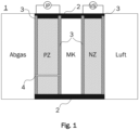
- Fig. 1 shows a schematic sectional view of a broadband lambda probe 1, which has a pump cell PZ, a measuring chamber MK (or measuring space or measuring gap), and a measuring cell NZ (or reference cell or Nernst cell).
- the pump cell PZ is placed adjacent to an exhaust gas flow. Adjacent to the pump cell PZ is the measuring chamber MK.
- the measuring cell NZ for measuring a measuring voltage.
- the Lambda sensor 1 is formed in a layered structure consisting of a pump cell PZ, a measuring chamber MK, and a measuring cell NZ.
- the pump cell PZ and the measuring cell NZ each have electrodes 3 separated by a solid electrolyte, for example, zirconium dioxide.
- the lambda sensor 1 has a pump cell PZ with a diffusion channel 4 and a regulator VSR.
- the pump cell PZ is supplied with a pumping current by a power supply, so that the pump cell PZ pumps oxygen from the exhaust gas into or out of the measuring chamber MK.
- the pump cell and the measuring cell are heated to an operating temperature of, for example, approximately 800°C by means of a heater 2. At this temperature, the solid electrolyte of the pump cell PZ and the measuring cell NZ is permeable to oxygen ions.
- the oxygen content of the sample gas in the measuring chamber MK is influenced, on the one hand, by the exhaust gas entering the measuring chamber MK through the diffusion channel 4 and, on the other hand, by the pumping current IP.
- the pumping current IP pumps oxygen from the exhaust gas through the solid electrolyte into the measuring chamber MK or from the measuring chamber MK to the exhaust gas.
- a lambda value of 1 is always present when the voltage VS at the measuring cell NZ is 450 mV.
- the pump current IP resulting from this control can be used as a sensor signal that is characteristic and meaningful for the oxygen content in the exhaust gas stream.
- Such a broadband lambda sensor is used, for example, to monitor the combustion process in a gas boiler burner.
- the burner can then be controlled based on the lambda sensor's measured values.
- Faultless lambda sensor operation is important. In the event of a sensor defect, If the sensor contacts or control are defective, the lambda sensor may deliver faulty signals, which can lead to faulty burner control.
- the measured air/fuel ratio then no longer matches the actual air/fuel ratio in the exhaust stream, and undesirable and potentially dangerous concentrations of carbon monoxide or unburned hydrocarbons may be emitted.
- ⁇ >> 1 combustion efficiency can be dramatically reduced.
- the present invention is based on the object of providing a method with which a fault in a lambda sensor can be reliably detected in order to prevent the occurrence of a dangerous operating condition in a gas burner.
- the object is achieved by a method according to claim 1.
- the object is achieved by a gas burner according to claim 9.
- the object is achieved by a heating system according to claim 10.
- Fig. 4 shows a flowchart of an exemplary method for operating a burner, for example, a gas burner of a heating system, which has a broadband lambda probe 1 for exhaust gas monitoring.
- the method steps are designated by numbers S1 to S29. Transitions between method steps are represented by solid arrows. Dashed arrows illustrate the storage or reading of values measured and/or calculated in the method, which are designated by letters a to i.
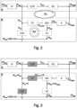
- Fig. 2 and Fig. 3 The control schemes shown provide an overview of the process, particularly of the function blocks F3 and F4. A detailed description of the individual process steps S1 to S29 follows based on the Fig. 4 .
- Function blocks F1, F2, F3, F5, and F6 are essentially implemented similarly in prior art methods.
- Function block F4, i.e., the probe test mode, is the subject of the present invention.
- the exemplary method according to the invention described below can enable the use of a commercially available, inexpensive, non-intrinsically safe broadband lambda probe, such as those used in the automotive sector, in a safety environment, such as a gas burner, without the aid of additional sensors.
- the measuring method of the broadband lambda sensor 1 is based on operating two cells (measuring cell VZ and pumping cell PZ) and a measuring chamber MK in a separate closed control circuit, which is Fig. 2 is illustrated.
- Fig. 2 shows a control diagram of a grass burner with a broadband lambda probe in normal operation (first operating state).
- the block labeled A represents a higher-level control circuit R1 of a combustion control unit of the gas burner.
- the setpoint of the residual oxygen content in the flue gas can be determined, for example, using a desired air ratio ⁇ .
- a gas burner is usually operated with excess air, i.e. with an air ratio ⁇ > 1.
- the setpoint O2 setpoint of the residual oxygen content in the flue gas can be determined as a volume concentration from the desired air ratio ⁇ .
- the first operating state (regulated operation) of the gas burner comprises in particular the steps: measuring (step S12) a residual oxygen content (e) in the exhaust gas; comparing (Step S14) comparing the measured residual oxygen content (e) with a predetermined target value (f) and determining a deviation; regulating (Step S15) the degree of opening of the gas control valve as a function of a deviation; measuring the measured voltage at the measuring cell NZ; comparing the measured voltage with a predetermined target voltage and determining a deviation; and regulating the residual oxygen content in the exhaust gas via the measured value of lambda sensor 1.
- the pump current can be regulated as a function of the deviation.
- a gas burner is usually operated with a substantially constant air flow.
- the combustion control system uses a gas control valve and the O2 regulator (O2R) to regulate the volume flow of the supplied gas (fuel) depending on the deviation between the target IP and the actual IP.
- O2R O2 regulator
- the controlled system RS in Fig. 2 Summarizes the burner's transmission behavior from the gas control valve to the measurement of the residual oxygen content in the flue gas (O2).
- the control system RS can be influenced by, among other things, the flame gauze, combustion, and heat exchanger.
- the broadband lambda sensor forms, as in Fig. 2 (Block B) illustrates, its own closed control loop R2 for oxygen measurement.
- Exhaust gas with the residual oxygen content O2 exhaust gas enters the measuring chamber MK through the diffusion channel 4 and contributes an oxygen quantity O2 in to the oxygen content O2 MK in the measuring chamber MK.
- the cell voltage VS ist is measured via the measuring cell NZ.
- the oxygen quantity O2 pump is also pumped into the measuring chamber MK or out of the measuring chamber MK through the pump cell PZ.
- the burner control unit receives an incorrect measured value IP ist and then regulates an incorrect residual oxygen content in the flue gas O2 flue gas out.
- IP ist and VS ist typically present measured variables
- Both the pump current IP and the cell voltage VS are controlled variables that are always regulated to the setpoint by the two controllers (VS controller VSR and O2 controller O2R).
- the operating mode of the gas burner is cyclically changed according to the invention so that additional measured values can be derived from the control circuit R2 of the oxygen measurement.
- the second operating state is referred to as probe test mode.
- the control scheme of the probe test mode is based on Fig. 3 described.
- the O2 regulator O2R is deactivated. This can be achieved, for example, by setting IP and IP to be virtually equal. This ensures that the residual oxygen content in the flue gas (O2) is kept constant. In other words, the opening degree of the gas control valve remains unchanged, and the burner is operated in controlled mode.
- the inactive elements are in Fig. 3 shown hatched.
- a process value VS test_act (g) is derived from the cell voltage VS actual by averaging (S21). This value is calculated in subsequent process steps (S24 and S25) and subsequently monitored for limits. This performs a plausibility check so that errors in the broadband probe are detected if the process value does not lie within specified limits.
- This method can be used to detect defects in the pump cell PZ, as well as in the diffusion channel 4.
- the method requires a fault-free measuring cell VZ. This is continuously monitored separately by measuring the internal resistance R IVS . The required procedure is specified by the manufacturer of the broadband lambda sensor. If this value lies within a tolerance band (S5), the measuring cell VZ is fault-free.
- a possible cell voltage drift is also adjusted. This is done by calibrating the pump current IP in air before and after each burner operation (probe calibration S6 and S26). If the deviation between both values is within a defined tolerance range, VS test_actual or VS test from the last burner operation is proportionally included in the setpoint VS test_setpoint (S28), resulting in a new, adapted setpoint for VS test .
- step S1 the burner is error-free and is in standby mode.
- step S2 a check is made to determine whether a burner request is present from a higher-level temperature controller. If a burner request is present (yes in S2), this provides the start signal for burner operation. If there is no burner request (no in S2), the burner remains in standby mode.
- step S3 the broadband lambda sensor 1 is activated.
- Activating the broadband lambda sensor 1 is a standard procedure performed according to the manufacturer's specifications.
- the broadband lambda sensor 1 is first heated using the heating electrodes 2, and then the cell voltage is adjusted to 450 mV.
- the cell resistance R IVS is measured in step S4. This measurement is also a standard procedure performed according to the manufacturer's specifications of the broadband lambda sensor 1. For this purpose, the measuring cell current I CP is switched on and off, while the cell voltage VS is measured, and the internal resistance of the cell (cell resistance) R IVS is calculated from this. The cell resistance R IVS is output as measured value d and stored.
- step S5 the cell resistance R IVS measured in step S4 is compared with a limit value, which is set, for example, to 400 ohms. If the cell resistance R IVS is less than the limit value (yes), the method proceeds to step S6.
- a limit value violation (no) i.e., if a cell resistance R IVS greater than the limit value is measured, leads to a safety shutdown in step S29.
- the variables A, B, C and offset are coefficients of the sensor characteristic curve, which are stored in the combustion control unit.
- step S7 a check is performed to determine whether the calibration factor Cal21 1 (value a) calculated in step S6 lies within a defined tolerance band, for example, by comparing the deviation between the calibration factor Cal21 1 and a setpoint with a limit value Cal21 obs (value c). If the calculated calibration factor Cal21 1 is not within the tolerance band (no in S7), the burner is shut down safely in step S29. If the calculated calibration factor Cal21 1 lies within the tolerance band Cal21 obs (yes in S7), the method continues to step S8.
- Calibration in air is required to compensate for manufacturing tolerances, sensor aging effects, and environmental influences such as atmospheric pressure.
- a deviation of the calibration factor Cal21 1 from the nominal value, defined as the tolerance band Cal21 obs is interpreted as a sensor error, resulting in a safety shutdown (step S29).
- step S8 a check is made to determine whether the burner request is still active. If the burner request is active (yes in S8), the burner is operated in regular mode (continue to step S9). If the burner request is no longer active (no in S8), the process continues in step S26 with a new probe calibration in air.
- the controlled normal operation (first operating state) of the burner corresponds to steps S8 to S17.
- the burner is ignited.
- step S9 power modulation begins according to the specifications of the higher-level temperature controller.
- the probe test mode is activated according to the parameterized cycle time.
- the cycle time is determined, for example, from the EN 12067 standard and is derived from the The hazard potential of a faulty condition of the system (gas burner) and its duration depend on this.
- a typical cycle time for a gas burner, for example, is 120 seconds.
- step S11 a query is made as to whether the test mode of lambda sensor 1 is requested according to the cycle duration from the previous step S10. If this is not the case (no in step S11), the method proceeds to step S12, and the burner continues to operate in controlled normal mode. If the query indicates that the test mode is requested (yes in step S11), the burner switches to the active test mode, and the method continues to step S18.
- step S12 the burner is operated in controlled normal mode, with the regular probe control circuit R2 active and providing a measured pumping current IP actual, which is transmitted to the burner control unit. From the measured pumping current IP actual, the actual value of the residual oxygen content (e) in the flue gas can be calculated using a characteristic curve.
- step S13 the combustion control calculates the actual value of the residual oxygen content O2 (measured value e) in the flue gas from the measured pump current IP ist and the sensor characteristic curve according to the following formula:
- O 2 ist A ⁇ IP ⁇ Offset 2 ⁇ Kal 21 2 + B ⁇ IP ⁇ Offset ⁇ Kal 21 + C
- the variables A, B, C and offset are coefficients of the sensor characteristic curve, which are stored in the combustion control unit.
- step S14 the O2 controller in the combustion control unit compares the setpoint O2 target (value f) with the calculated actual value of the residual oxygen content O2 actual (value e) from step S13 and determines a deviation.
- the setpoint O2 target is specified via the parameterization of the combustion control unit. If the two values match (yes), or the deviation is smaller than a specified limit, the process continues to step S16. If the values are not equal, or the If the deviation is greater than the specified limit value, the gas quantity V Gas , in particular the degree of opening of a gas control valve as a control variable, is adjusted in step S15 depending on the determined deviation.
- the gas quantity V Gas in particular the degree of opening of a gas control valve as a control variable
- step S16 the internal resistance of the measuring cell R IVS (value d) is continuously measured during normal burner operation. This measurement can be performed using the same method as the measurement in step S4.
- step S5 Analogous to step S5, the measured cell resistance R IVS (d) is compared with the limit value in step 17. If the limit value is met (yes), the process returns to step 8. If the measured cell resistance R IVS is greater than the limit value (no), the safety shutdown occurs in step S29.
- step S18 the O2 sensor test mode is active, but the burner's regular operation (O2 controller) is no longer active. The burner is therefore no longer in regulated, but rather in controlled operation. This state typically lasts approximately five seconds. In the sensor control circuit, the power supply to the pump cell is switched off.
- step S19 an O2 partial pressure equalization is performed between the combustion chamber and the measuring chamber of lambda sensor 1. This process can typically take less than one second. A longer time of two seconds can ensure that partial pressure equalization can be performed even under disturbed conditions (e.g., a blocked diffusion passage).
- step S20 the cell voltage Vs is measured. Instead of 450 mV, this is now typically 60 mV (depending on the residual oxygen content of the exhaust gas).
- step S21 the measured cell voltage VS is averaged over one second to compensate for possible signal noise.
- the average cell voltage in test mode VS test_act (g) is stored as an intermediate result. This value is not Not directly, but in a weighted form (see step S24), for monitoring purposes to make the process more robust against disturbances. If the residual oxygen content (O2) in the combustion chamber at the time of the probe test deviates slightly from the target value (O2) due to external conditions such as wind or gas pressure fluctuations, this should not influence the probe test result too significantly.
- step S22 the voltage supplies of the pump cell PZ and the VS regulator are reactivated so that the pump current IP returns to the initial level and thus the cell voltage VS of 450 mV is regulated.
- Regulating the cell voltage to 450 mV takes approximately one second.
- an extended delay of, for example, two seconds is performed to ensure increased robustness, since the control response may be slower with an aged lambda sensor 1.
- step S24 the intermediate result from step S21 VS test_akt (g) is included in the test result VS test (h) using a moving average with a weighting of, for example, 20%.
- step S25 the result of the probe test VS test (h) is compared with a dynamic limit value VS test _soll (i). If the test result VS test is below the limit value (yes), normal operation continues in step S8. If the dynamic limit value VS test_soll (i) is violated, an immediate safety shutdown occurs in step S29.
- step S26 the flame is first shut off and the gas burner or lambda sensor 1 is re-ventilated. During the re-ventilation, lambda sensor 1 is recalibrated in air. The result of the calibration is a second calibration factor Cal21 2 (b).
- step S27 a check is carried out to determine whether the second calibration factor Cal21 2 (b) after burner run deviates from the first calibration factor Cal21 1 (a) from burner start-up (see step S6). If the deviation (i.e., the difference between values a and b) is greater than a permissible limit (no in S27), a safety shutdown occurs in step S29.
- An excessive deviation between calibration factors a and b indicates a fault in lambda probe 1 or the burner system (e.g., flue gas recirculation), meaning safe operation can no longer be guaranteed.
- step S28 a new target value VS test_soll (i) can be determined for the sensor test. This is necessary because the cell voltage VS can drift over its lifetime. This can, in particular, increase the robustness of the process.
- the target value VS test_soll (i) is corrected or included by 20% with the last result of the sensor test VS test (h). The result is a weighted average that allows long-term correction of the target value so that short-term disturbances do not distort the target value too much. This can further increase the robustness of the process.
- the new target value VS test_soll is saved as value i and used in the next sensor test (step S25).
Landscapes
- Engineering & Computer Science (AREA)
- Chemical & Material Sciences (AREA)
- Health & Medical Sciences (AREA)
- Life Sciences & Earth Sciences (AREA)
- General Engineering & Computer Science (AREA)
- Mechanical Engineering (AREA)
- Combustion & Propulsion (AREA)
- Biochemistry (AREA)
- Analytical Chemistry (AREA)
- General Health & Medical Sciences (AREA)
- General Physics & Mathematics (AREA)
- Immunology (AREA)
- Pathology (AREA)
- Physics & Mathematics (AREA)
- Electrochemistry (AREA)
- Chemical Kinetics & Catalysis (AREA)
- Molecular Biology (AREA)
- Measuring Oxygen Concentration In Cells (AREA)
- Investigating Or Analyzing Materials By The Use Of Electric Means (AREA)
Claims (10)
- Procédé pour faire fonctionner un brûleur à gaz, qui présente une sonde lambda (1) disposée dans le flux de gaz d'échappement du brûleur à gaz pour mesurer une teneur en oxygène résiduel dans le gaz d'échappement,le brûleur à gaz fonctionnant dans un premier état de fonctionnement en mode de régulation, la teneur en oxygène résiduel dans le gaz d'échappement étant régulée par le biais de la valeur de mesure de la sonde lambda (1),caractérisé en ce que le brûleur à gaz effectue dans un deuxième état de fonctionnement un contrôle d'erreur de la sonde lambda (1) avec les étapes suivantes :détermination d'une tension de contrôle actuelle (h) d'une cellule de mesure (NZ) de la sonde lambda (1) lorsque l'alimentation électrique d'une cellule de pompage (PZ) de la sonde lambda (1) est coupée ;comparaison (S25) de la tension de contrôle actuelle (h) avec une tension de consigne de contrôle prédéfinie (i) et détermination d'un écart ; etsi l'écart dépasse une valeur limite prédéfinie :réalisation d'une coupure de sécurité (S29) ; oufonctionnement du brûleur à gaz dans le premier état de fonctionnement.
- Procédé selon la revendication 1, dans lequel :la sonde lambda (1) est une sonde lambda à large bande ;le brûleur à gaz présente en outre un automate de combustion pour réguler ou commander une quantité de gaz amenée au brûleur à gaz par le biais d'une soupape de régulation de gaz ; etl'automate de combustion règle le degré d'ouverture de la soupape de régulation de gaz dans le deuxième état de fonctionnement à une valeur prédéfinie.
- Procédé selon la revendication 1 ou 2, dans lequel le brûleur à gaz est déplacé de manière cyclique après écoulement d'un intervalle de temps prédéfini du premier état de fonctionnement dans le deuxième état de fonctionnement (S10).
- Procédé selon au moins l'une quelconque des revendications précédentes, dans lequel la détermination de la tension de contrôle actuelle (h) comprend :la mesure (S20) d'une tension de mesure au niveau de la cellule de mesure (NZ) ;la formation (S21) d'une valeur moyenne temporelle (g) de la tension de mesure mesurée sur une période de temps définie ;le calcul (S24) de la tension de contrôle actuelle (h) par formation d'une valeur moyenne pondérée à partir de la valeur moyenne temporelle de la tension de mesure (g) et d'une tension de contrôle mémorisée d'un contrôle d'erreur précédent de la sonde lambda (1) ; etla mémorisation de la tension de contrôle actuelle (h).
- Procédé selon la revendication 4, dans lequel le procédé dans le deuxième état de fonctionnement comprend en outre, après la formation de la valeur moyenne temporelle (g) de la tension de mesure mesurée :la mise en circuit (S22) de l'alimentation électrique de la cellule de pompage (PZ) ;la mesure de la tension de mesure au niveau de la cellule de mesure (NZ) ;la comparaison de la tension de mesure mesurée avec une tension de consigne prédéfinie et la détermination d'un écart ; etla régulation de la teneur en oxygène résiduel dans le gaz d'échappement en fonction de l'écart.
- Procédé selon au moins l'une quelconque des revendications précédentes, dans lequel le brûleur à gaz effectue dans un troisième état de fonctionnement, lorsqu'aucune demande de brûleur actif n'est présente, un étalonnage de sonde (S26) sur l'air, avec les étapes suivantes :l'arrêt de la flamme ;la post-aération de la sonde lambda (1) ;le calcul d'un premier facteur d'étalonnage (b) ;la comparaison (S27) du premier facteur d'étalonnage (b) avec un deuxième facteur d'étalonnage mémorisé (a) et la détermination d'un écart ; etsi l'écart dépasse une valeur limite prédéfinie, réalisation de la coupure de sécurité (S29) du brûleur à gaz ; ousi l'écart ne dépasse pas la valeur limite prédéfinie, le calcul (S28) de la tension de consigne de contrôle (i) par formation d'une valeur moyenne pondérée à partir d'une tension de consigne de contrôle mémorisée et de la tension de contrôle actuelle (h) déterminée dans le deuxième état de fonctionnement ; etla mémorisation de la tension de consigne de contrôle (i).
- Procédé selon au moins l'une quelconque des revendications précédentes, comprenant en outre :la mesure (S4, S16) d'une résistance interne (d) de la cellule de mesure (NZ) ;la comparaison (S5, S17) de la résistance interne mesurée (d) avec une valeur de consigne prédéfinie et la détermination d'un écart ; etsi l'écart dépasse une valeur limite prédéfinie, la réalisation d'une coupure de sécurité (S29) ; ousi l'écart ne dépasse pas la valeur limite prédéfinie, le fonctionnement du brûleur à gaz dans le premier état de fonctionnement.
- Procédé selon au moins l'une quelconque des revendications précédentes, comprenant en outre :la réalisation d'un étalonnage de sonde (S6) sur l'air et la détermination d'un deuxième facteur d'étalonnage (a) ;la mémorisation du deuxième facteur d'étalonnage (a) ;la comparaison (S7) du deuxième facteur d'étalonnage (a) avec une valeur de consigne prédéfinie (c) et la détermination d'un écart ; etsi l'écart dépasse une valeur limite prédéfinie, la réalisation d'une coupure de sécurité (S29) ; ousi l'écart ne dépasse pas la valeur limite prédéfinie, le fonctionnement du brûleur à gaz dans le premier état de fonctionnement.
- Brûleur à gaz pour une installation de chauffage, comprenant :une sonde lambda (1) disposée dans le flux de gaz d'échappement du brûleur à gaz pour mesurer une teneur en oxygène résiduel dans un gaz d'échappement du brûleur à gaz, la sonde lambda (1) présentant une cellule de mesure (NZ) et une cellule de pompage (PZ) ; etun automate de combustion pour réguler un débit volumique d'un combustible amené au moyen d'une soupape de régulation de gaz,caractérisé en ce que le brûleur à gaz est configuré pour effectuer un procédé selon au moins l'une quelconque des revendications 1 à 8.
- Installation de chauffage pour un bâtiment, caractérisée en ce que l'installation de chauffage comprend un brûleur à gaz selon la revendication 9.
Applications Claiming Priority (2)
| Application Number | Priority Date | Filing Date | Title |
|---|---|---|---|
| DE102020204089.3A DE102020204089B3 (de) | 2020-03-30 | 2020-03-30 | Verfahren zum Betreiben eines Gasbrenners |
| PCT/EP2021/057284 WO2021197900A1 (fr) | 2020-03-30 | 2021-03-22 | Procédé pour le fonctionnement d'un brûleur à gaz et brûleur à gaz pour la mise en œuvre du procédé |
Publications (3)
| Publication Number | Publication Date |
|---|---|
| EP4127565A1 EP4127565A1 (fr) | 2023-02-08 |
| EP4127565B1 true EP4127565B1 (fr) | 2025-06-11 |
| EP4127565C0 EP4127565C0 (fr) | 2025-06-11 |
Family
ID=75278004
Family Applications (1)
| Application Number | Title | Priority Date | Filing Date |
|---|---|---|---|
| EP21715191.9A Active EP4127565B1 (fr) | 2020-03-30 | 2021-03-22 | Procédé pour le fonctionnement d'un brûleur à gaz et brûleur à gaz pour la mise en oeuvre du procédé |
Country Status (4)
| Country | Link |
|---|---|
| US (1) | US12613033B2 (fr) |
| EP (1) | EP4127565B1 (fr) |
| DE (1) | DE102020204089B3 (fr) |
| WO (1) | WO2021197900A1 (fr) |
Families Citing this family (3)
| Publication number | Priority date | Publication date | Assignee | Title |
|---|---|---|---|---|
| CN114440255B (zh) * | 2022-01-21 | 2025-07-22 | 慈溪中科众茂环保热电有限公司 | 一种火电厂锅炉燃烧控制方法、系统、存储介质及智能终端 |
| DE102023108441A1 (de) * | 2023-04-03 | 2024-10-10 | Viessmann Climate Solutions Se | Heizgerät und Verfahren zum Betrieb eines Heizgerätes |
| DE102023111213A1 (de) * | 2023-05-02 | 2024-11-07 | Viessmann Climate Solutions Se | Verfahren zum Starten eines Gasbrenners |
Family Cites Families (10)
| Publication number | Priority date | Publication date | Assignee | Title |
|---|---|---|---|---|
| US5462439A (en) * | 1993-04-19 | 1995-10-31 | Keith; Arlie L. | Charging batteries of electric vehicles |
| DE10110810A1 (de) * | 2001-03-06 | 2002-09-12 | Siemens Building Tech Ag | Anordnung eines Feuerungsautomaten für einen Gas- oder Ölbrenner |
| DE102008043124A1 (de) | 2008-10-23 | 2010-04-29 | Robert Bosch Gmbh | Verfahren zur Diagnose einer in einem Abgaskanal eines Verbrennungsmotors angeordneten Lambdasonde und Vorrichtung zur Durchführung des Verfahrens |
| DE102011077171A1 (de) * | 2011-05-18 | 2012-11-22 | Robert Bosch Gmbh | Verfahren und Steuereinheit zur Überwachung von Kabelfehlern an einer Breitband-Lambdasonde |
| DE102012213601A1 (de) | 2012-08-01 | 2014-02-06 | Continental Automotive Gmbh | Überprüfung einer Lambdasonde |
| US9575030B2 (en) * | 2012-09-17 | 2017-02-21 | Aem Performance Electronics | Digital controller for an oxygen sensor |
| DE102013105466B3 (de) * | 2013-05-28 | 2014-10-30 | Karl Dungs Gmbh & Co. Kg | Messvorrichtung und Verfahren zur Messung des Sauerstoffgehaltes eines Rauchgasstroms |
| KR101601756B1 (ko) * | 2014-09-30 | 2016-03-10 | 현대오트론 주식회사 | 산소 센서의 단선 진단 방법 및 그 장치 |
| EP3064937B1 (fr) | 2015-03-06 | 2021-02-24 | Elster GmbH | Procédé de fonctionnement d'une sonde lambda large bande |
| DE102018211599A1 (de) | 2018-07-12 | 2020-01-16 | Robert Bosch Gmbh | Verfahren zum Betreiben eines Sensors zur Erfassung mindestens einer Eigenschaft eines Messgases in einem Messgasraum |
-
2020
- 2020-03-30 DE DE102020204089.3A patent/DE102020204089B3/de active Active
-
2021
- 2021-03-22 WO PCT/EP2021/057284 patent/WO2021197900A1/fr not_active Ceased
- 2021-03-22 EP EP21715191.9A patent/EP4127565B1/fr active Active
- 2021-03-22 US US17/915,352 patent/US12613033B2/en active Active
Also Published As
| Publication number | Publication date |
|---|---|
| US20230144467A1 (en) | 2023-05-11 |
| WO2021197900A1 (fr) | 2021-10-07 |
| EP4127565A1 (fr) | 2023-02-08 |
| DE102020204089B3 (de) | 2021-07-29 |
| EP4127565C0 (fr) | 2025-06-11 |
| US12613033B2 (en) | 2026-04-28 |
Similar Documents
| Publication | Publication Date | Title |
|---|---|---|
| EP4127565B1 (fr) | Procédé pour le fonctionnement d'un brûleur à gaz et brûleur à gaz pour la mise en oeuvre du procédé | |
| DE102012211687B4 (de) | Verfahren und Steuereinheit zur Erkennung eines Spannungsoffsets einer Spannungs-Lambda-Kennlinie | |
| DE102015205971B4 (de) | Verfahren zum Betreiben einer Sonde | |
| EP2625580B1 (fr) | Procédé de réglage d'une température d'un élément capteur | |
| DE60001005T2 (de) | Methode zur Steuerung und Diagnose der Heizung des Abgaszusammensetzungsensors eines Motors | |
| DE19838334B4 (de) | Diagnoseeinrichtung für eine potentiometrische, elektrisch beheizte Abgassonde zur Regelung von Verbrennungsprozessen | |
| DE4344961A1 (de) | Auswertevorrichtung für das Signal einer Sauerstoffsonde | |
| DE10312732B4 (de) | Verfahren zum Betrieb einer Messsonde zur Messung einer Gaskonzentration | |
| EP2912447A1 (fr) | Procédé et dispositif de diagnostic du conduit de référence à l'air d'une sonde lambda à large bande | |
| WO1999057555A1 (fr) | PROCEDE POUR LA DETERMINATION DE LA CONCENTRATION EN NO¿x? | |
| DE102016207516B4 (de) | Verfahren zur Alterungsbestimmung einer zur Ermittlung einer Gaskonzentration eines Gasgemischs ausgebildeten Sonde einer Brennkraftmaschine | |
| DE69221185T2 (de) | Vorrichtung zur Bestimmung der Betriebsbereitschaft einer Lambda-Sonde | |
| DE19625899C2 (de) | Verfahren zum Betreiben einer Sauerstoffsonde | |
| EP3064937B1 (fr) | Procédé de fonctionnement d'une sonde lambda large bande | |
| WO1999056012A1 (fr) | Procede d'epuration de gaz residuaires a reglage de precision | |
| DE102011010074B4 (de) | Verfahren zur Überprüfung der Funktionstüchtigkeit eines Sensors und zur Regelung einer Feuerungsanlage | |
| EP1084399B1 (fr) | Procede pour la determination de la concentration en nox | |
| DE102010039188A1 (de) | Verfahren zur Erfassung einer Eigenschaft eines Gases in einem Messgasraum | |
| DE102011017015B4 (de) | Verfahren zum Betreiben einer Lambdasonde | |
| EP3224464B1 (fr) | Procédé de détection d'un écart de tension au moins dans une plage d'une courbe caractéristique de tension lambda | |
| DE102014224942A1 (de) | Verfahren zur Erkennung eines Zustands eines Heizelements in einem Sensor | |
| DE102020104084A1 (de) | Verfahren zur Überwachung und Regelung eines Prozesses einer Gastherme und Gastherme | |
| EP3155251B1 (fr) | Procédé permettant d'évaluer l'écart d'une courbe caractéristique | |
| DE102012211685A1 (de) | Verfahren und Vorrichtung zur Bestimmung einer Luftzahl Lambda mit einem Gas-Sensor | |
| DE102016210420B3 (de) | Verfahren zum Betreiben eines Sauerstoffsensors, Computerprogrammprodukt und Sauerstoffsensor |
Legal Events
| Date | Code | Title | Description |
|---|---|---|---|
| STAA | Information on the status of an ep patent application or granted ep patent |
Free format text: STATUS: UNKNOWN |
|
| STAA | Information on the status of an ep patent application or granted ep patent |
Free format text: STATUS: THE INTERNATIONAL PUBLICATION HAS BEEN MADE |
|
| PUAI | Public reference made under article 153(3) epc to a published international application that has entered the european phase |
Free format text: ORIGINAL CODE: 0009012 |
|
| STAA | Information on the status of an ep patent application or granted ep patent |
Free format text: STATUS: REQUEST FOR EXAMINATION WAS MADE |
|
| 17P | Request for examination filed |
Effective date: 20221031 |
|
| AK | Designated contracting states |
Kind code of ref document: A1 Designated state(s): AL AT BE BG CH CY CZ DE DK EE ES FI FR GB GR HR HU IE IS IT LI LT LU LV MC MK MT NL NO PL PT RO RS SE SI SK SM TR |
|
| DAV | Request for validation of the european patent (deleted) | ||
| DAX | Request for extension of the european patent (deleted) | ||
| GRAP | Despatch of communication of intention to grant a patent |
Free format text: ORIGINAL CODE: EPIDOSNIGR1 |
|
| STAA | Information on the status of an ep patent application or granted ep patent |
Free format text: STATUS: GRANT OF PATENT IS INTENDED |
|
| INTG | Intention to grant announced |
Effective date: 20250203 |
|
| GRAS | Grant fee paid |
Free format text: ORIGINAL CODE: EPIDOSNIGR3 |
|
| GRAA | (expected) grant |
Free format text: ORIGINAL CODE: 0009210 |
|
| STAA | Information on the status of an ep patent application or granted ep patent |
Free format text: STATUS: THE PATENT HAS BEEN GRANTED |
|
| RAP1 | Party data changed (applicant data changed or rights of an application transferred) |
Owner name: VIESSMANN HOLDING INTERNATIONAL GMBH |
|
| AK | Designated contracting states |
Kind code of ref document: B1 Designated state(s): AL AT BE BG CH CY CZ DE DK EE ES FI FR GB GR HR HU IE IS IT LI LT LU LV MC MK MT NL NO PL PT RO RS SE SI SK SM TR |
|
| REG | Reference to a national code |
Ref country code: GB Ref legal event code: FG4D Free format text: NOT ENGLISH |
|
| REG | Reference to a national code |
Ref country code: CH Ref legal event code: EP |
|
| REG | Reference to a national code |
Ref country code: DE Ref legal event code: R096 Ref document number: 502021007710 Country of ref document: DE |
|
| REG | Reference to a national code |
Ref country code: IE Ref legal event code: FG4D Free format text: LANGUAGE OF EP DOCUMENT: GERMAN |
|
| U01 | Request for unitary effect filed |
Effective date: 20250611 |
|
| U07 | Unitary effect registered |
Designated state(s): AT BE BG DE DK EE FI FR IT LT LU LV MT NL PT RO SE SI Effective date: 20250620 |
|
| PG25 | Lapsed in a contracting state [announced via postgrant information from national office to epo] |
Ref country code: ES Free format text: LAPSE BECAUSE OF FAILURE TO SUBMIT A TRANSLATION OF THE DESCRIPTION OR TO PAY THE FEE WITHIN THE PRESCRIBED TIME-LIMIT Effective date: 20250611 |
|
| PG25 | Lapsed in a contracting state [announced via postgrant information from national office to epo] |
Ref country code: NO Free format text: LAPSE BECAUSE OF FAILURE TO SUBMIT A TRANSLATION OF THE DESCRIPTION OR TO PAY THE FEE WITHIN THE PRESCRIBED TIME-LIMIT Effective date: 20250911 Ref country code: GR Free format text: LAPSE BECAUSE OF FAILURE TO SUBMIT A TRANSLATION OF THE DESCRIPTION OR TO PAY THE FEE WITHIN THE PRESCRIBED TIME-LIMIT Effective date: 20250912 |
|
| PG25 | Lapsed in a contracting state [announced via postgrant information from national office to epo] |
Ref country code: HR Free format text: LAPSE BECAUSE OF FAILURE TO SUBMIT A TRANSLATION OF THE DESCRIPTION OR TO PAY THE FEE WITHIN THE PRESCRIBED TIME-LIMIT Effective date: 20250611 |
|
| PG25 | Lapsed in a contracting state [announced via postgrant information from national office to epo] |
Ref country code: RS Free format text: LAPSE BECAUSE OF FAILURE TO SUBMIT A TRANSLATION OF THE DESCRIPTION OR TO PAY THE FEE WITHIN THE PRESCRIBED TIME-LIMIT Effective date: 20250911 |
|
| PG25 | Lapsed in a contracting state [announced via postgrant information from national office to epo] |
Ref country code: IS Free format text: LAPSE BECAUSE OF FAILURE TO SUBMIT A TRANSLATION OF THE DESCRIPTION OR TO PAY THE FEE WITHIN THE PRESCRIBED TIME-LIMIT Effective date: 20251011 |
|
| PG25 | Lapsed in a contracting state [announced via postgrant information from national office to epo] |
Ref country code: SM Free format text: LAPSE BECAUSE OF FAILURE TO SUBMIT A TRANSLATION OF THE DESCRIPTION OR TO PAY THE FEE WITHIN THE PRESCRIBED TIME-LIMIT Effective date: 20250611 |
|
| PG25 | Lapsed in a contracting state [announced via postgrant information from national office to epo] |
Ref country code: CZ Free format text: LAPSE BECAUSE OF FAILURE TO SUBMIT A TRANSLATION OF THE DESCRIPTION OR TO PAY THE FEE WITHIN THE PRESCRIBED TIME-LIMIT Effective date: 20250611 |
|
| PG25 | Lapsed in a contracting state [announced via postgrant information from national office to epo] |
Ref country code: PL Free format text: LAPSE BECAUSE OF FAILURE TO SUBMIT A TRANSLATION OF THE DESCRIPTION OR TO PAY THE FEE WITHIN THE PRESCRIBED TIME-LIMIT Effective date: 20250611 |
|
| PG25 | Lapsed in a contracting state [announced via postgrant information from national office to epo] |
Ref country code: SK Free format text: LAPSE BECAUSE OF FAILURE TO SUBMIT A TRANSLATION OF THE DESCRIPTION OR TO PAY THE FEE WITHIN THE PRESCRIBED TIME-LIMIT Effective date: 20250611 |
|
| U20 | Renewal fee for the european patent with unitary effect paid |
Year of fee payment: 6 Effective date: 20260219 |
|
| PLBE | No opposition filed within time limit |
Free format text: ORIGINAL CODE: 0009261 |
|
| STAA | Information on the status of an ep patent application or granted ep patent |
Free format text: STATUS: NO OPPOSITION FILED WITHIN TIME LIMIT |
|
| REG | Reference to a national code |
Ref country code: CH Ref legal event code: L10 Free format text: ST27 STATUS EVENT CODE: U-0-0-L10-L00 (AS PROVIDED BY THE NATIONAL OFFICE) Effective date: 20260423 |