EP4127732B1 - Vorrichtung zur geschwindigkeitserfassung mit einer kielsonde - Google Patents
Vorrichtung zur geschwindigkeitserfassung mit einer kielsonde Download PDFInfo
- Publication number
- EP4127732B1 EP4127732B1 EP21700476.1A EP21700476A EP4127732B1 EP 4127732 B1 EP4127732 B1 EP 4127732B1 EP 21700476 A EP21700476 A EP 21700476A EP 4127732 B1 EP4127732 B1 EP 4127732B1
- Authority
- EP
- European Patent Office
- Prior art keywords
- probe
- holes
- dynamic pressure
- flow velocity
- sensor
- Prior art date
- Legal status (The legal status is an assumption and is not a legal conclusion. Google has not performed a legal analysis and makes no representation as to the accuracy of the status listed.)
- Active
Links
Images

Classifications
-
- G—PHYSICS
- G01—MEASURING; TESTING
- G01P—MEASURING LINEAR OR ANGULAR SPEED, ACCELERATION, DECELERATION, OR SHOCK; INDICATING PRESENCE, ABSENCE, OR DIRECTION, OF MOVEMENT
- G01P5/00—Measuring speed of fluids, e.g. of air stream; Measuring speed of bodies relative to fluids, e.g. of ship, of aircraft
- G01P5/14—Measuring speed of fluids, e.g. of air stream; Measuring speed of bodies relative to fluids, e.g. of ship, of aircraft by measuring differences of pressure in the fluid
- G01P5/16—Measuring speed of fluids, e.g. of air stream; Measuring speed of bodies relative to fluids, e.g. of ship, of aircraft by measuring differences of pressure in the fluid using Pitot tubes, e.g. Machmeter
- G01P5/165—Arrangements or constructions of Pitot tubes
-
- G—PHYSICS
- G01—MEASURING; TESTING
- G01P—MEASURING LINEAR OR ANGULAR SPEED, ACCELERATION, DECELERATION, OR SHOCK; INDICATING PRESENCE, ABSENCE, OR DIRECTION, OF MOVEMENT
- G01P1/00—Details of instruments
- G01P1/02—Housings
- G01P1/026—Housings for speed measuring devices, e.g. pulse generator
-
- G—PHYSICS
- G01—MEASURING; TESTING
- G01P—MEASURING LINEAR OR ANGULAR SPEED, ACCELERATION, DECELERATION, OR SHOCK; INDICATING PRESENCE, ABSENCE, OR DIRECTION, OF MOVEMENT
- G01P13/00—Indicating or recording presence, absence, or direction, of movement
- G01P13/0006—Indicating or recording presence, absence, or direction, of movement of fluids or of granulous or powder-like substances
- G01P13/0066—Indicating or recording presence, absence, or direction, of movement of fluids or of granulous or powder-like substances by using differences of pressure in the fluid
-
- G—PHYSICS
- G01—MEASURING; TESTING
- G01F—MEASURING VOLUME, VOLUME FLOW, MASS FLOW OR LIQUID LEVEL; METERING BY VOLUME
- G01F1/00—Measuring the volume flow or mass flow of fluid or fluent solid material wherein the fluid passes through a meter in a continuous flow
- G01F1/05—Measuring the volume flow or mass flow of fluid or fluent solid material wherein the fluid passes through a meter in a continuous flow by using mechanical effects
- G01F1/34—Measuring the volume flow or mass flow of fluid or fluent solid material wherein the fluid passes through a meter in a continuous flow by using mechanical effects by measuring pressure or differential pressure
- G01F1/36—Measuring the volume flow or mass flow of fluid or fluent solid material wherein the fluid passes through a meter in a continuous flow by using mechanical effects by measuring pressure or differential pressure the pressure or differential pressure being created by the use of flow constriction
- G01F1/40—Details of construction of the flow constriction devices
- G01F1/44—Venturi tubes
-
- G—PHYSICS
- G01—MEASURING; TESTING
- G01F—MEASURING VOLUME, VOLUME FLOW, MASS FLOW OR LIQUID LEVEL; METERING BY VOLUME
- G01F1/00—Measuring the volume flow or mass flow of fluid or fluent solid material wherein the fluid passes through a meter in a continuous flow
- G01F1/05—Measuring the volume flow or mass flow of fluid or fluent solid material wherein the fluid passes through a meter in a continuous flow by using mechanical effects
- G01F1/34—Measuring the volume flow or mass flow of fluid or fluent solid material wherein the fluid passes through a meter in a continuous flow by using mechanical effects by measuring pressure or differential pressure
- G01F1/36—Measuring the volume flow or mass flow of fluid or fluent solid material wherein the fluid passes through a meter in a continuous flow by using mechanical effects by measuring pressure or differential pressure the pressure or differential pressure being created by the use of flow constriction
- G01F1/40—Details of construction of the flow constriction devices
- G01F1/46—Pitot tubes
-
- G—PHYSICS
- G01—MEASURING; TESTING
- G01P—MEASURING LINEAR OR ANGULAR SPEED, ACCELERATION, DECELERATION, OR SHOCK; INDICATING PRESENCE, ABSENCE, OR DIRECTION, OF MOVEMENT
- G01P13/00—Indicating or recording presence, absence, or direction, of movement
- G01P13/02—Indicating direction only, e.g. by weather vane
- G01P13/025—Indicating direction only, e.g. by weather vane indicating air data, i.e. flight variables of an aircraft, e.g. angle of attack, side slip, shear, yaw
-
- G—PHYSICS
- G01—MEASURING; TESTING
- G01P—MEASURING LINEAR OR ANGULAR SPEED, ACCELERATION, DECELERATION, OR SHOCK; INDICATING PRESENCE, ABSENCE, OR DIRECTION, OF MOVEMENT
- G01P5/00—Measuring speed of fluids, e.g. of air stream; Measuring speed of bodies relative to fluids, e.g. of ship, of aircraft
- G01P5/14—Measuring speed of fluids, e.g. of air stream; Measuring speed of bodies relative to fluids, e.g. of ship, of aircraft by measuring differences of pressure in the fluid
- G01P5/16—Measuring speed of fluids, e.g. of air stream; Measuring speed of bodies relative to fluids, e.g. of ship, of aircraft by measuring differences of pressure in the fluid using Pitot tubes, e.g. Machmeter
Definitions
- the invention relates to a device for speed detection with a keel probe, which has a flow velocity probe which is enclosed by a casing body forming a Venturi nozzle.
- Such a device is known, for example, from WO 87/06710 A1
- a device for measuring the flow velocity of a free flow in space is known, which, starting from a known Venturi tube, can be used to measure the flow velocity in a pipe over a wide angular range with respect to the flow direction or the blowing direction.
- the static pressures are measured at two longitudinally different points of a flow body with varying thickness, and their difference is calculated.
- the flow velocity probe can be enclosed by a jacket body forming a Venturi nozzle.
- US5365795 discloses a keel probe having a flow velocity probe enclosed by a casing body forming a venturi nozzle.
- a similar device is disclosed by GB2558709 A , which, however, does not have a venturi nozzle and static pressure probes.
- the use of dynamic pressure sensors to determine directional information shows the US2019301969 A1 .
- the DE 19735724 A1 discloses a measuring sensor for attachment to a support frame in a gas turbine engine, wherein the measuring sensor comprises a casing tube having a front opening for the inlet of flow air and a plurality of openings in the tube casing.
- a pressure sensor and a temperature sensor are arranged adjacent to one another in such a way that both the pressure sensor and the temperature sensor are exposed to a defined flow, for which purpose at least six vent openings are provided in the tube.
- a keel probe is a further development of a pitot tube and is used to measure the total pressure in moving flows.
- the keel probe has the advantage over a pitot tube that it is less sensitive to the angle of attack.
- the keel probe essentially consists of a venturi nozzle with a pitot probe inside.
- the venturi nozzle deflects the flow in an axial direction, thus ensuring a more constant flow towards the pitot probe.
- the position of the pitot probe in the axial direction within the venturi nozzle also plays a key role in the sensitivity to the angle of attack.
- a disadvantage is the difficulty of determining the exact wind direction in space for different sensor orientations. Using the keel probe principle, wind speed can be reliably measured, but not wind direction, over large angular ranges. Problems can arise at angles of attack greater than +-60°.
- Venturi nozzles consist of a piece of pipe with a narrowing of the inlet and a widening of the outlet cross-section, for example by two cones directed towards each other, which are possibly united by a cylindrical tube at the point of their smallest diameter.
- the inflow direction can be determined using a multi-hole probe. In practice, two- or four-hole probes, four-hole probes, wedge probes, or cylindrical probes are used for this purpose.
- the risk of determining the inflow direction using the pressure method is the reliability of the calibration.
- the problem with calibration is that the flow around the probe head is highly unsteady when the direction changes. In addition, the flow around it depends heavily on the turbulent inflow. Local separation effects in oblique inflow can occur at different locations depending on the inflow, which means that calibration must be performed for all conditions.
- Inertial navigation systems are 3D measurement systems with an inertial measurement unit as the central sensor unit with multiple acceleration and angular rate sensors. By integrating the measured accelerations and angular rates, the spatial movement of vehicles or aircraft, for example, is continuously determined. However, an absolute position like with GPS cannot be determined.
- the main advantage of inertial navigation systems is that they can be operated without a reference, i.e., independently of any positioning signals. However, sensor drift is unavoidable.
- a method and apparatus for monitoring fluid dynamic resistance on an object such as a bicycle, a ground vehicle, a watercraft, an aircraft, or part of a wind turbine are known.
- an array of sensors is provided which detects the power consumption for propelling the object, the air speed and direction relative to the movement of the object, and the traveling speed of the object.
- the following sensor values can also be recorded: temperature, altitude, and humidity for measuring air density.
- Sensor values can also indicate inclination angle and forward acceleration.
- One from the US 2018 321272 A1 known fluid detection device comprises an outer body having a front side, a rear side and an interior space, wherein the outer body contains a fluid inlet arranged at the front side, one or more vent openings arranged behind the fluid inlet to allow the passage of fluid through the fluid detection device and at least one load sensor, the coupled to the inner body to measure a fluid drag force on the inner body.
- the invention is therefore based on the object of creating a device for speed detection of the type described above, which enables proper measurement of wind speed and wind direction with compact dimensions.
- the casing body is designed as a multi-hole pitot tube with holes distributed around the casing circumference.
- the holes in the casing body, distributed around the casing circumference, are preferably evenly distributed in a plane perpendicular to the longitudinal axis of the flow velocity tube, and the holes associated with a common plane are connected to the pitot tube sensors via pitot channels of equal length.
- the keel probe provides the flow velocity S u US , the x-component of the incident flow velocity in the sensor-fixed coordinate system, i.e. in the direction of the flow velocity probe's longitudinal axis.
- the flow velocity can be measured in the keel probe using a Pitot tube, ultrasound, or a hot wire measurement.
- the rectification of the flow by means of the keel probe arrangement is crucial for determining the main wind velocity S u US , which is independent of the inflow direction.
- the flow velocity can preferably be recorded using a pitot tube within the keel probe and a static pressure sensor to determine a differential pressure on the inner casing, which provides information regarding the relative wind speed. Problems can arise at angles of attack greater than +-60°. For these angular ranges, A query can be stored in an evaluation software that detects these areas and informs the user. The user can then position the sensor in a better position for the angle of attack.
- the shroud probe i.e. the shroud body designed as a multi-hole pitot tube with holes in the shroud body distributed around the shroud circumference, enables the measurement of an angle transformation matrix A SW with the two flow angles, the vertical angle of attack ⁇ and the side angle of attack ⁇ , referred to the sensor-fixed coordinate system.
- the angle transformation matrix is measured via the holes in the shroud body distributed around the shroud circumference, i.e. via the pressure measuring points on the shroud surface.
- the individual measuring points for determining the angle of attack can be located at the front inside, front outside, rear outside, rear inside, and centrally outside on the shroud body.
- the inventive device for velocity detection solves this problem by measuring the flow velocity in the sensor's longitudinal direction and the approach flow direction separately.
- the flow velocity in the sensor direction is measured by a keel probe that is insensitive to the approach flow angle, while the approach flow direction itself is measured by a multi-hole pitot tube with holes in the shroud body distributed around the circumference. All three approach flow components can then be calculated from both sensors.
- dynamic pressure sensors be connected to the holes, with the holes preferably connecting to the dynamic pressure sensors via dynamic pressure channels.
- Each dynamic pressure channel This leads to a separate dynamic pressure sensor in order to exclude mutual influences on the measurements of the individual measuring points.
- the holes in the casing body are evenly distributed around the longitudinal axis of the flow velocity probe in a plane perpendicular to the longitudinal axis of the flow velocity probe, so that the flow angle can be accurately calculated from any differential pressures present at the measuring points in a plane.
- the holes assigned to a common plane are connected to the dynamic pressure sensors via dynamic pressure channels of equal length, ensuring consistent measurement conditions, particularly response times, for all measuring points assigned to a common plane.
- the dynamic disturbances of the object movement itself can be measured and corrected accordingly.
- the position and velocity of the device in space can be determined.
- the absolute wind velocity S v W can be calculated from the incident flow velocity S v US .
- v W S v US S ⁇ v S S
- a temperature (°C) and/or humidity (RH) sensor can be embedded in the jacket body.
- additional sensors via technical interfaces, i.e., in particular, to integrate them into the speed detection sensor according to the invention, and thus to collect additional environmental data (e.g., climate data such as temperature and humidity or road surface data, etc.) in a data logger and include it in immediate or later evaluation.
- additional environmental data e.g., climate data such as temperature and humidity or road surface data, etc.
- the invention is recommended for use in the development of new aerodynamic vehicles or parts thereof, in particular to validate CFD simulations with real data.
- Another application is the expansion of the capabilities of automated and autonomous driving systems to include the recording of local flow conditions and flow ratios.
- a drift occurs due to an integration error inherent in the system, which accumulates over the measurement period.
- This integration error can be compensated for using the wind data, which precisely determines and stores the wind speed and direction at any time.
- the individual sensor signals can be fused using various filters, such as complementary filters, Kalman filters, or similar. This allows integration errors to be compensated for by using the quasi-stationary states of the individual sensors for comparison. If, for example, the sensor does not detect any oblique flow, ie the main flow velocity is the correct speed and the angular rates are also constant, it is possible to compare the integrated traveling speed with the measured wind speed.
- the device according to the invention has a compact housing in which all calculations are carried out internally, for which purpose a computer unit with an autonomous power supply is provided.
- the device 1 for speed detection comprises a keel probe 2, which has a flow velocity probe which is enclosed by a casing body 3 forming a Venturi nozzle, wherein the casing body 3 is designed as a multi-hole dynamic pressure probe with holes 4 in the casing body 3 distributed over the casing circumference.
- the holes 4 in the casing body 3, which are arranged distributed over the casing circumference, are preferably arranged uniformly distributed around the longitudinal axis of the flow velocity probe in a plane perpendicular to a longitudinal axis of the flow velocity probe.
- At least two spaced planes with holes distributed around the circumference of the casing are provided in the direction of the flow velocity probe's longitudinal axis. However, a single plane can also be sufficient.
- An inertial navigation system (INS), a global positioning system (GPS), and an evaluation and communication unit are preferably arranged in the shell body.
- Temperature (°C) and/or humidity (RH) sensors are also preferably provided in the shell body.
- Fig. 3 a) to d ) are exemplary movement and flow conditions which can lead to incorrect measurement results with individual sensors according to the state of the art.
- the same global wind S v W prevails.
- the inflow direction of the wind vector S v US is in the direction of the sensor axis. Using the direction known, for example, from the INS and/or GPS data and the magnitude of the sensor velocity S v S, the global wind S v W can be calculated.
- the device comprises a wind sensor with a keel probe and a multi-hole pitot tube, means for speed and position detection, and additional sensors for measuring air temperature, humidity, and ambient pressure. All calculations are performed by a microcontroller integrated in the device.
- the sensor output variables are subsequently transmitted to a terminal device via a wired or wireless interface, such as WLAN, Bluetooth, ANT+, or the like.
- the sensor has its own power supply. This comes either from a built-in battery with a charging circuit or comprises components with particularly low power consumption. Energy demand which obtains the required energy from energy generation from the environment, for example from the wind.
Landscapes
- Physics & Mathematics (AREA)
- General Physics & Mathematics (AREA)
- Engineering & Computer Science (AREA)
- Aviation & Aerospace Engineering (AREA)
- Indicating Or Recording The Presence, Absence, Or Direction Of Movement (AREA)
- Measuring Fluid Pressure (AREA)
- Testing Or Calibration Of Command Recording Devices (AREA)
Description
- Die Erfindung bezieht sich auf eine Vorrichtung zur Geschwindigkeitserfassung mit einer Kielsonde, die eine Strömungsgeschwindigkeitssonde aufweist, die von einem eine Venturidüse bildenden Mantelkörper umfasst ist.
- Eine derartige Vorrichtung ist beispielsweise aus der
WO 87/06710 A1 US5365795 offenbart eine Kielsonde, die eine Strömungsgeschwindigkeitssonde aufweist, die von einem eine Venturidüse bildenden Mantelkörper umfasst wird. Eine ähnliche Vorrichtung offenbart dieGB2558709 A US2019301969 A1 . - Die
DE 19735724 A1 offenbart einen Messfühler zur Befestigung an einem Tragrahmen in einem Gasturbinentriebwerk, wobei der Messfühler ein Mantelrohr umfasst, das eine stirnseitige Öffnung zum Einlass von Strömungsluft und mehrere Öffnungen im Rohrmantel aufweist. Innerhalb des Mantelrohrs sind ein Drucksensor und ein Temperatursensor derart nebeneinanderliegend angeordnet sind, dass sowohl der Drucksensor als auch der Temperatursensor in definierter Weise angeströmt werden, wozu mindestens sechs Vent-Öfnungen im Rohr vorgesehen sind. - Eine Kielsonde entspricht einer Weiterentwicklung eines Pitotrohres und dient zur Messung des Totaldrucks in bewegten Strömungen. Die Kielsonde hat gegenüber einem Pitotrohr den Vorteil, dass sie eine geringere Sensitivität bezüglich des Anströmwinkels aufweist. Die Kielsonde besteht im Wesentlichen aus einer Venturidüse, in deren Inneren sich eine Pitotsonde befindet. Die Venturidüse lenkt dabei die Strömung in Axialrichtung um und sorgt somit für eine konstantere Anströmung der Pitotsonde. Neben der Geometrie der Venturidüse spielt auch die Position der Pitotsonde in Axialrichtung gesehen in der Venturidüse eine wesentliche Rolle für die Sensitivität bezüglich des Anströmwinkels. Ein Nachteil liegt in der Schwierigkeit der Bestimmung der exakten Windrichtung im Raum für verschiedene Orientierungen des Sensors. Durch Verwendung des Kielsonden Prinzip kann zwar die Windgeschwindigkeit, nicht aber die Windrichtung für große Winkelbereiche belastbar erfasst werden. Probleme können sich bei Anströmwinkel ergeben die größer +-60° sind.
- Venturidüsen bestehen aus einem Rohrstück mit einer Verengung des Eintritts- und einer Aufweitung des Austrittsquerschnitts, beispielsweise durch zwei gegeneinander gerichtete Konen, die an der Stelle ihres geringsten Durchmessers gegebenenfalls über ein Zylinderrohr vereint sind.
- Die Bestimmung der Anströmrichtung kann mittels einer Mehrlochsonde erfolgen. In der Praxis sind zu diesem Zweck Zwei- oder Vierfingerlochsonden, Vierfingersonden, Keilsonden oder Zylindersonden im Einsatz. Das Risiko bei der Bestimmung der Anströmrichtung mittels Druckverfahren ist die Belastbare Kalibrierung. Das Problem bei der Kalibrierung ist, dass die Umströmung des Sondenkopfes bei Richtungsänderung höchst Instationär ist. Zusätzlich hängt die Umströmung stark von der Turbulenten Anströmung ab. Lokale Ablöseeffekte bei Schräganströmung können abhängig von der Anströmung an unterschiedlichen Stellen auftreten wodurch die Kalibrierung für sämtliche Bedingungen durchgeführt werden muss.
- Aktuell verfügbare Messgeräte zum Bestimmen der Windgeschwindigkeit sind meist sehr groß und vor allem in Verbindung mit der notwendigen Auswerteeinheit nicht überall ganz einfach zu montieren. Windmessungen an bewegten Objekten werden heutzutage überwiegend mit Pitot-, Staudruck- und Mehrlochsonden durchgeführt. Bei Messungen an bewegten Objekten ändern sich daher neben der Zeit auch der Messort und die Windrichtung ständig. Je nach Dynamik des bewegten Objektes ergeben sich daraus Störungen der eigentlichen Windmessung.
- Trägheitsnavigationssysteme sind 3-D-Messsysteme mit einer inertialen Messeinheit als zentraler Sensoreinheit mit mehreren Beschleunigungs- und Drehratensensoren. Durch Integration der gemessenen Beschleunigungen und Drehraten wird laufend die räumliche Bewegung beispielsweise von Fahr- oder Flugzeugen bestimmt. Eine Absolutposition wie mit einem GPS kann damit allerdings nicht bestimmt werden. Der Hauptvorteil von Trägheitsnavigationssystemen ist, dass dieses referenzlos betrieben werden können, also unabhängig von jeglichen Ortungssignalen. Allerdings ist ein Drift der Sensoren unvermeidlich.
- Aus der
WO 2017 197 524 A1 sind ein Verfahren und eine Vorrichtung zum Überwachen des fluiddynamischen Widerstands an einem Objekt wie einem Fahrrad, einem Bodenfahrzeug, einem Wasserfahrzeug, einem Flugzeug oder einem Teil einer Windkraftanlage bekannt. Dazu ist eine Anordnung von Sensoren vorgesehen, welche eine Leistungsaufnahme zum Antreiben des Objekts, die Luftgeschwindigkeit und -richtung relativ zur Bewegung des Objekts und eine Fahrgeschwindigkeit des Objekts erfasst. Es können auch folgende Sensorwerte aufgenommen werden, Temperatur, Höhe und Luftfeuchtigkeit zur Messung der Luftdichte. Sensorwerte können auch Neigungswinkel und Vorwärtsbeschleunigung anzeigen. - Eine aus der
US 2018 321272 A1 bekannte Fluiderfassungsvorrichtung umfasst einen Außenkörper mit einer Vorderseite, einer Rückseite und einem Innenraum, wobei der Außenkörper einen an der Vorderseite angeordneten Fluideinlass enthält, eine oder mehrere Entlüftungsöffnungen, die hinter dem Fluideinlass angeordnet sind, um den Durchgang von Fluid durch die Fluiderfassungsvorrichtung zu ermöglichen und mindestens einen Lastsensor, der mit dem Innenkörper gekoppelt ist, um eine Fluidwiderstandskraft auf den Innenkörper zu messen. - Der Erfindung liegt somit die Aufgabe zugrunde, eine Vorrichtung zur Geschwindigkeitserfassung der eingangs geschilderten Art zu schaffen, die bei kompakten Abmessungen eine ordnungsgemäße Messung von Windgeschwindigkeit und Windrichtung ermöglicht.
- Die Erfindung löst diese Aufgabe dadurch, dass der Mantelkörper als Mehrlochstaudrucksonde mit über den Mantelumfang verteilt angeordneten Löchern im Mantelkörper ausgebildet ist, dass die über den Mantelumfang verteilt angeordneten Löcher im Mantelkörper in einer senkrecht zu einer Strömungsgeschwindigkeitssondenlängsachse stehenden Ebene um die Strömungsgeschwindigkeitssondenlängsachse vorzugsweise gleichverteilt angeordnet sind und dass die einer gemeinsamen Ebene zugeordneten Löcher über Staudruckkanäle gleicher Länge an den Staudrucksensoren anschließen. Mit diesen Maßnahmen ist eine ordnungsgemäße Messung von Windgeschwindigkeit und Windrichtung möglich.
- Die Kielsonde liefert die Strömungsgeschwindigkeit SuUS , die x-Komponente der Anströmgeschwindigkeit im sensorfesten Koordinatensystem, also in Richtung der Strömungsgeschwindigkeitssondenlängsachse. Die Messung der Strömungsgeschwindigkeit in der Kielsonde kann über ein Pitotrohr, mittels Ultraschall oder über eine Hitzdraht Messung erfolgen. Entscheidend ist die Gleichrichtung der Strömung mittels der Kielsondenanordnung zur Bestimmung der anströmrichtungsunabhängigen Hauptwindgeschwindigkeit SuUS. Vorzugsweise kann die Strömungsgeschwindigkeit über ein Staudruckrohr innerhalb der Kielsonde sowie einen statischen Druckaufnehmer zur Ermittlung eines Differenzdruckes am Innenmantel aufgenommen werden, was Information bezüglich der relativen Windgeschwindigkeit liefert. Probleme können sich bei Anströmwinkeln ergeben die größer +-60° sind. Für diese Winkelbereiche muss eine Abfrage in einer Auswertesoftware hinterlegt werden, welche diese Bereiche erkennt und einen Benutzer darüber informiert. Der Benutzer kann daraufhin den Sensor in einer für den Anströmwinkel bessere Position bringen.
- Die Mantelsonde, also der als Mehrlochstaudrucksonde mit über den Mantelumfang verteilt angeordneten Löchern im Mantelkörper ausgebildete Mantelkörper ermöglicht die Messung einer Winkeltransformationsmatrix ASW mit den beiden Strömungswinkeln, dem Höhenanstellwinkel α, und dem Seitenanströmwinkel β , bezogen auf das Sensorfeste Koordinatensystem. Die Messung der Winkeltransformationsmatrix erfolgt über die über den Mantelumfang verteilt angeordneten Löcher im Mantelkörper, also über die Druckmesspunkte an der Manteloberfläche. Die einzelnen Messpunkte zur Bestimmung der Anströmwinkel können dabei vorne innen, vorne außen, hinten außen, hinten innen und mittig außen am Mantelkörper angeordnet sein.
- Ein weiteres Problem heute üblicher Windmesser an bewegten Objekten ist eine Kalibrierung der einzelnen Windkomponenten. So werden bei klassischen Mehrlochsonden alle drei Windkomponenten über dieselben Druckmesspunkte am Sondenkopf aufgenommen. Das macht eine Kalibrierung schwierig, da die Berechnung der absoluten Geschwindigkeit aus den einzelnen Drucksignalen sehr sensitiv auf Winkeländerungen ist. Dadurch wird auch die Messgenauigkeit der Anströmrichtungen stark beeinflusst. Die erfindungsgemäße Vorrichtung zur Geschwindigkeitserfassung löst dieses Problem indem die Strömungsgeschwindigkeit in Sensorlängsrichtung und die Anströmrichtung getrennt gemessen werden. Die Strömungsgeschwindigkeit in Sensorrichtung wird durch eine hinsichtlich des Anströmwinkels unempfindliche Kielsonde gemessen, während die Anströmrichtung selbst durch eine Mehrlochstaudrucksonde mit über den Mantelumfang verteilt angeordneten Löchern im Mantelkörper gemessen wird. Aus beiden Sensoren können dann alle drei Anströmkomponenten berechnet werden.
- Für bestmögliche Messergebnisse wird vorgeschlagen, dass an die Löcher Staudrucksensoren angeschlossen sind, wobei die Löcher vorzugsweise über Staudruckkanäle an die Staudrucksensoren anschließen. Jeder Staudruckkanal führt dabei zu einem gesonderten Staudrucksensor, um gegenseitige Beeinflussungen der Messungen der einzelnen Messpunkte ausschließen zu können.
- Die über den Mantelumfang verteilt angeordneten Löcher im Mantelkörper sind in einer senkrecht zu einer Strömungsgeschwindigkeitssondenlängsachse stehenden Ebene um die Strömungsgeschwindigkeitssondenlängsachse gleichverteilt angeordnet, damit der Strömungswinkel sauber aus etwaigen vorliegenden Differenzdrücken an den Messpunkten einer Ebene errechnet werden kann. Dazu schließen die einer gemeinsamen Ebene zugeordneten Löcher über Staudruckkanäle gleicher Länge an den Staudrucksensoren an, um für alle einer gemeinsamen Ebene zugeordneten Messpunkte gleiche Messverhältnisse, insbesondere Ansprechzeiten, gewährleisten zu können.
- Zur Verbesserung der Auflösung des zu bestimmenden Strömungswinkels kann es von Vorteil seine, wenn in Richtung der Strömungsgeschwindigkeitssondenlängsachse wenigstens zwei beabstandete Ebenen mit über den Mantelumfang verteilt angeordneten Löchern vorgesehen sind.
- Durch ein vorsehen eines, vorzugsweise im Mantelkörper eingebetteten, inertialen Navigationssystems und/oder eines, vorzugsweise im Mantelkörper eingebetteten, globalen Positionsbestimmungssystems, also durch wenigstens einen zusätzlichen Positions- und Lagesensoren im Multisensor können die dynamischen Störeinflüsse der Objektbewegung selbst gemessen und entsprechend korrigiert werden. Dazu können die Lage und die Geschwindigkeit der Vorrichtung im Raum bestimmt werden. Durch die Zusätzliche Information der drei dimensionalen Vorrichtungsgeschwindigkeit SvS im Raum kann die absolute Windgeschwindigkeit SvW aus der Anströmgeschwindigkeit SvUS berechnet werden.

- Zur Verbesserung der Meßgenauigkeit können im Mantelkörper ein Temperatur-(°C) und/oder Luftfeuchtigkeitssensor (rF) eingebettet sein.
- Zusätzlich ist es über technische Schnittstellen möglich, weitere Sensoren zu koppeln, also insbesondere in den erfindungsgemäßen Sensor zur Geschwindigkeitserfassung zu integrieren, und damit ergänzende Umgebungsdaten (z.B. Klimadaten wie Temperatur und Luftfeuchtigkeit oder Fahrbahndaten usw.) in einem Datalogger zu sammeln und in die sofortige oder spätere Auswertung einzubeziehen. Die Erfindung empfiehlt sich für einen Einsatz in der Entwicklung neuer aerodynamischer Fahrzeuge oder von Teilen davon, insbesondere um CFD-Simulationen mit Echtdaten validieren zu können.
- Mit der erfindungsgemäßen Vorrichtung können reale, lokale Anströmbedingungen an bewegten Objekten erfasst werden.
- Ein weiterer Einsatzfall ist die Kompetenzerweiterung von automatisierten und autonomen Fahrsystemen um die Erfassung der lokalen Strömungsbedingungen und Strömungsverhältnissen.
- Bei der Berechnung der diversen Geschwindigkeiten im Raum aus den mit dem Trägheitsnavigationssystem aufgenommen Sensordaten kommt es infolge eines systemimmanenten Integrationsfehlers, der sich über die Messdauer aufsummiert, zu einem Drift. Mit Hilfe der Winddaten, welche Windgeschwindigkeit und Windrichtung in jedem Zeitpunkt genau bestimmen und abspeichern, kann dieser Integrationsfehler ausgeglichen werden. Über verschiedene Filter, wie Komplementärfilter, Kalmannfilter od. dgl. können die einzelnen Sensorsignale fusioniert werden. Dadurch können Integrationsfehler ausgeglichen werden indem quasistationäre Zustände der einzelnen Sensoren zum Abgleich verwendet werden. Erkennt der Sensor beispielsweise keinerlei Schräganströmung, d.h. ist die Hauptströmungsgeschwindigkeit die Richtige Geschwindigkeit und sind zusätzlich die Drehraten konstant, besteht die Möglichkeit die integrierte Fahrgeschwindigkeit mit der gemessenen Windgeschwindigkeit abzugleichen.
- Die erfindungsgemäße Vorrichtung weist ein kompaktes Gehäuse auf, in dem alle Berechnungen intern durchgeführt werden, wozu eine Rechnereinheit mit autonomer Stromversorgung vorgesehen ist.
- In der Zeichnung ist der Erfindungsgegenstand beispielsweise dargestellt. Es zeigen
- Fig. 1
- eine Vorrichtung zur Geschwindigkeitserfassung in einer Ansicht von schräg vorne,
- Fig. 2
- die Vorrichtung in einer Ansicht von schräg hinten,
- Fig. 3
- a) bis d) die Vorrichtung in einem vereinfachten Schnitt in unterschiedlichen Bewegungs- und Strömungszuständen und
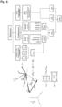
- Fig. 4
- ein Schaltbild einer erfindungsgemäßen Vorrichtung.
- Die Vorrichtung 1 zur Geschwindigkeitserfassung umfasst eine Kielsonde 2, die eine Strömungsgeschwindigkeitssonde aufweist, die von einem eine Venturidüse bildenden Mantelkörper 3 umfasst ist, wobei der Mantelkörper 3 als Mehrlochstaudrucksonde mit über den Mantelumfang verteilt angeordneten Löchern 4 im Mantelkörper 3 ausgebildet ist.
- Die über den Mantelumfang verteilt angeordneten Löcher 4 im Mantelkörper 3 sind in einer senkrecht zu einer Strömungsgeschwindigkeitssondenlängsachse stehenden Ebene um die Strömungsgeschwindigkeitssondenlängsachse vorzugsweise gleichverteilt angeordnet.
- In Richtung der Strömungsgeschwindigkeitssondenlängsachse sind wenigstens zwei beabstandete Ebenen mit über den Mantelumfang verteilt angeordneten Löchern vorgesehen. Mit einer Ebene kann allerdings auch das Auslangen gefunden werden.
- Im Mantelkörper sind vorzugsweise ein Trägheitsnavigationssystem INS, ein globales Positionsbestimmungssystem GPS zusammen mit einer Auswerte- und Kommunikationseinheit angeordnet. Zudem sind vorzugsweise Temperatur- (°C) und/oder Luftfeuchtigkeitssensoren (rF) im Mantelkörper vorgesehen.
- In
Fig. 3 a) bis d ) sind beispielhafte Bewegungs- und Strömungszustände dargestellt, welche bei Einzelsensoren gemäß dem Stand der Technik zu falschen Messergebnissen führen können. - Fall a) Die Sensorgeschwindigkeit SvS und der Windvektor SvUS zeigen in die entgegengesetzte Richtung. Die Ergebnisse sind brauchbar, allerdings wäre eine Ausrichtung der Vorrichtung im Wind gemäß Fall c) besser bzw. genauer.
- In den Fällen b) & d) herrscht ein gleicher globaler Wind SvW vor. Im Fall b) ist die Anströmrichtung des Windvektors SvUS in Richtung der Sensorachse. Mit der Beispielsweise aus den INS und/oder GPS Daten bekannten Richtung und dem Betrag der Sensorgeschwindigkeit SvS kann der globale Wind SvW errechnet werden.
- Im Fall d) ist die Sensorgeschwindigkeit SvS in Richtung der Sensorachse gerichtet. Die von der Mehrlochstaudrucksonde aufgenommene Schräganströmung läßt den Anströmwinkel errechnen und zeigt das Vorhandensein von globalem Wind SvW. Beide Fälle b) & d) liefern das gleiche Ergebnis.
- Die erfindungsgemäße Vorrichtung umfasst einen Windsensor mit Kielsonde und Mehrlochstaudrucksonde, Mittel zur Geschwindigkeits- und Lageerfassung sowie zusätzliche Sensorik zur Messung der Lufttemperatur, Luftfeuchte und Umgebungsdruck. Sämtliche Berechnungen werden mit einem in der Vorrichtung Verbauten Microcontroller durchgeführt. Die Sensor-Ausgangsgrößen werden in weiterer Folge über eine Kabel- oder eine Kabellose Schnittstelle, wie WLAN, Bluetooth, ANT+, od. dgl. an ein Endgerät übertragen. Der Sensor verfügt über eine eigene Energieversorgung. Diese kommt entweder aus einem eingebauten Akku mit Aufladeschaltung aus oder umfasst Komponenten besonders geringem Energiebedarf welche die benötigte Energie mit Energieerzeugung aus der Umgebung, beispielsweise dem Wind, beziehen.
Claims (6)
- Vorrichtung (1) zur Geschwindigkeitserfassung mit einer Kielsonde (2), die eine Strömungsgeschwindigkeitssonde aufweist, die von einem eine Venturidüse bildenden Mantelkörper (3) umfasst ist, dadurch gekennzeichnet, dass der Mantelkörper (3) als Mehrlochstaudrucksonde mit über den Mantelumfang verteilt angeordneten Löchern (4) im Mantelkörper (3) ausgebildet ist, dass die über den Mantelumfang verteilt angeordneten Löcher (4) im Mantelkörper in einer senkrecht zu einer Strömungsgeschwindigkeitssondenlängsachse stehenden Ebene um die Strömungsgeschwindigkeitssondenlängsachse vorzugsweise gleichverteilt angeordnet sind und dass die einer gemeinsamen Ebene zugeordneten Löcher (4) über Staudruckkanäle gleicher Länge an den Staudrucksensoren anschließbar sind.
- Vorrichtung nach Anspruch 1, dadurch gekennzeichnet, dass an die Löcher (4) Staudrucksensoren angeschlossen sind, wobei die Löcher (4) vorzugsweise über Staudruckkanäle an die Staudrucksensoren anschließen.
- Vorrichtung nach Anspruch 1, dadurch gekennzeichnet, dass in Richtung der Strömungsgeschwindigkeitssondenlängsachse wenigstens zwei beabstandete Ebenen mit über den Mantelumfang verteilt angeordneten Löchern (4) vorgesehen sind.
- Vorrichtung nach einem der Ansprüche 1 bis 3, gekennzeichnet durch ein, vorzugsweise im Mantelkörper (3) eingebettetes, Trägheitsnavigationssystem (INS).
- Vorrichtung nach einem der Ansprüche 1 bis 4, gekennzeichnet durch ein, vorzugsweise im Mantelkörper (3) eingebettetes, globales Positionsbestimmungssystem (GPS).
- Vorrichtung nach einem der Ansprüche 1 bis 4, gekennzeichnet durch einen, vorzugsweise im Mantelkörper (3) eingebetteten, Temperatur- (°C) und/oder Luftfeuchtigkeitssensor (rF).
Applications Claiming Priority (2)
| Application Number | Priority Date | Filing Date | Title |
|---|---|---|---|
| ATA50263/2020A AT523396B1 (de) | 2020-03-31 | 2020-03-31 | Vorrichtung zur Geschwindigkeitserfassung mit einer Kielsonde |
| PCT/AT2021/060004 WO2021195677A1 (de) | 2020-03-31 | 2021-01-11 | Vorrichtung zur geschwindigkeitserfassung mit einer kielsonde |
Publications (3)
| Publication Number | Publication Date |
|---|---|
| EP4127732A1 EP4127732A1 (de) | 2023-02-08 |
| EP4127732C0 EP4127732C0 (de) | 2025-07-09 |
| EP4127732B1 true EP4127732B1 (de) | 2025-07-09 |
Family
ID=74186362
Family Applications (1)
| Application Number | Title | Priority Date | Filing Date |
|---|---|---|---|
| EP21700476.1A Active EP4127732B1 (de) | 2020-03-31 | 2021-01-11 | Vorrichtung zur geschwindigkeitserfassung mit einer kielsonde |
Country Status (6)
| Country | Link |
|---|---|
| US (1) | US20230408543A1 (de) |
| EP (1) | EP4127732B1 (de) |
| AT (1) | AT523396B1 (de) |
| CA (1) | CA3176151A1 (de) |
| ES (1) | ES3041044T3 (de) |
| WO (1) | WO2021195677A1 (de) |
Families Citing this family (5)
| Publication number | Priority date | Publication date | Assignee | Title |
|---|---|---|---|---|
| SE544928C2 (en) * | 2021-05-12 | 2023-01-10 | Isak Jonsson Ab | Multi-hole pressure probe and use of such a probe |
| AT526977A1 (de) * | 2023-02-15 | 2024-09-15 | Windpuls Gmbh | Vorrichtung zum Messen von Windanströmungsbedingungen |
| GB202314758D0 (en) * | 2023-09-26 | 2023-11-08 | Univ Oxford Innovation Ltd | Probe for measuring fluid flow and a flow measuring system |
| AT528169A1 (de) * | 2024-04-04 | 2025-10-15 | Avl List Gmbh | Aerodynamik-Messgitter |
| CN118362753B (zh) * | 2024-06-19 | 2024-08-20 | 瑞科同创电力工程设计有限公司 | 一种摆针式传感器和风资源评估系统 |
Citations (1)
| Publication number | Priority date | Publication date | Assignee | Title |
|---|---|---|---|---|
| US5365795A (en) * | 1993-05-20 | 1994-11-22 | Brower Jr William B | Improved method for determining flow rates in venturis, orifices and flow nozzles involving total pressure and static pressure measurements |
Family Cites Families (13)
| Publication number | Priority date | Publication date | Assignee | Title |
|---|---|---|---|---|
| US2101858A (en) * | 1936-07-30 | 1937-12-14 | Andrew W Knisley | Static tube sleeve |
| WO1987006710A1 (fr) * | 1986-04-24 | 1987-11-05 | Roland Sommer | Dispositif et procede pour mesurer la vitesse d'un ecoulement libre dans l'espace |
| US4833917A (en) * | 1988-08-08 | 1989-05-30 | Southern Company Services, Inc. | Three-component velocity probe for large scale application |
| US5241866A (en) * | 1991-02-21 | 1993-09-07 | The United States Of America Respresented By The Administrator Of National Aeronautics And Space Administration | Probe shapes that measure time-averaged streamwise momentum and cross-stream turbulence intensity |
| DE19735724A1 (de) * | 1997-08-18 | 1999-02-25 | Bmw Rolls Royce Gmbh | Meßfühler für ein Gasturbinentriebwerk |
| WO2009091792A2 (en) * | 2008-01-15 | 2009-07-23 | Sysense, Inc. | A methodology for autonomous navigation and control of a tethered drogue |
| US9541429B2 (en) * | 2014-06-02 | 2017-01-10 | University Of Kansas | Systems, methods, and devices for fluid data sensing |
| US10585109B2 (en) * | 2014-06-02 | 2020-03-10 | University Of Kansas | Systems, methods, and devices for fluid data sensing |
| DE102015214443A1 (de) * | 2015-07-30 | 2017-02-02 | Siemens Aktiengesellschaft | Kielsonde |
| NL2017846A (en) * | 2015-12-21 | 2017-06-27 | Asml Netherlands Bv | Height Measurement Apparatus |
| CA3108201C (en) * | 2016-05-19 | 2023-03-28 | 1323079 Alberta Ltd. | Method and apparatus for monitoring fluid dynamic drag |
| GB2558709B (en) * | 2017-09-22 | 2019-02-20 | Garrood Barnaby | An airflow measurement device |
| CN108152529A (zh) * | 2017-11-02 | 2018-06-12 | 成都飞机工业(集团)有限责任公司 | 一种基于飞行参数计算风速及风向的方法 |
-
2020
- 2020-03-31 AT ATA50263/2020A patent/AT523396B1/de active
-
2021
- 2021-01-11 CA CA3176151A patent/CA3176151A1/en active Pending
- 2021-01-11 US US17/913,124 patent/US20230408543A1/en active Pending
- 2021-01-11 ES ES21700476T patent/ES3041044T3/es active Active
- 2021-01-11 WO PCT/AT2021/060004 patent/WO2021195677A1/de not_active Ceased
- 2021-01-11 EP EP21700476.1A patent/EP4127732B1/de active Active
Patent Citations (1)
| Publication number | Priority date | Publication date | Assignee | Title |
|---|---|---|---|---|
| US5365795A (en) * | 1993-05-20 | 1994-11-22 | Brower Jr William B | Improved method for determining flow rates in venturis, orifices and flow nozzles involving total pressure and static pressure measurements |
Also Published As
| Publication number | Publication date |
|---|---|
| US20230408543A1 (en) | 2023-12-21 |
| WO2021195677A1 (de) | 2021-10-07 |
| AT523396B1 (de) | 2021-08-15 |
| EP4127732C0 (de) | 2025-07-09 |
| AT523396A4 (de) | 2021-08-15 |
| EP4127732A1 (de) | 2023-02-08 |
| ES3041044T3 (en) | 2025-11-06 |
| CA3176151A1 (en) | 2021-10-07 |
Similar Documents
| Publication | Publication Date | Title |
|---|---|---|
| EP4127732B1 (de) | Vorrichtung zur geschwindigkeitserfassung mit einer kielsonde | |
| EP0266376B1 (de) | Vorrichtung und verfahren zur messung der strömungsgeschwindigkeit einer freien strömung im raum | |
| DE10001813C2 (de) | Meßsystem zur Ermittlung von Luftdaten eines Luftfahrzeuges sowie ein Verfahren zur Bestimmung der Luftdaten | |
| US4096744A (en) | Pressure sensor for determining airspeed, altitude and angle of attack | |
| US7480548B2 (en) | High-altitude capable wide velocity range flight velocity vector measurement probe and measurement system | |
| DE3881845T2 (de) | Verfahren und Vorrichtung zur Bestimmung von Luftgeschwindigkeit und -richtung. | |
| EP0073809A1 (de) | Drucksensor zur bestimmung von luftgeschwindigkeit, höhe und anflugwinkel. | |
| DE69931790T2 (de) | Luftdrucksensor | |
| DE2827104A1 (de) | Sonde zur druckmessung in einem luftstrom | |
| DE102005038205B4 (de) | Windkanal mit einem darin angeordneten Modell, insbesondere einem Modell eines Luftfahrzeugs, zur Erfassung und Auswertung einer Vielzahl von Messdaten sowie Verfahren | |
| EP0236569B1 (de) | Verfahren und Vorrichtung zur Ermittlung eines Anströmwinkels und/oder der Windgeschwindigkeit an einer ortsfesten oder bewegten Messstelle | |
| EP1314985B1 (de) | Luftdaten-Messvorrichtung und Luftdaten-Messsystem für Fluggeräte | |
| EP3185018B1 (de) | Durchflussmessgerät mit windgeschwindigkeitssensor | |
| US4702106A (en) | Method for determining the horizontal airspeed of helicopters in low speed ranges | |
| DE102015121703A1 (de) | Fluggerät zum Erfassen des Windvektors | |
| EP1020717B1 (de) | Pitot-statische sonde | |
| EP0457200B1 (de) | Verfahren zur Messung von Winkeln und Winkelkennlinien mit Hilfe eines Kreisels | |
| US3244001A (en) | Aerodynamic variables sensing device | |
| DE19919249A1 (de) | Koppelnavigationssystem | |
| DE102015121517B4 (de) | Verfahren und Vorrichtung zur Bestimmung eines Geschwindigkeitsvektors eines in der Umgegebung eines Fluggeräts herrschenden Windes, und Fluggerät | |
| EP4227689B1 (de) | Verfahren zur bestimmung von anströmparametern eines überschall-flugkörpers | |
| Shevchenko et al. | Multi-hole pressure probes to air data system for subsonic small-scale air vehicles | |
| GEENEN et al. | A system for testing airdata probes at high angles of attack using aground vehicle | |
| CN106248990A (zh) | 一种风场三维风速测定的便捷装置及制造和使用方法 | |
| DE4015800C2 (de) |
Legal Events
| Date | Code | Title | Description |
|---|---|---|---|
| STAA | Information on the status of an ep patent application or granted ep patent |
Free format text: STATUS: UNKNOWN |
|
| STAA | Information on the status of an ep patent application or granted ep patent |
Free format text: STATUS: THE INTERNATIONAL PUBLICATION HAS BEEN MADE |
|
| PUAI | Public reference made under article 153(3) epc to a published international application that has entered the european phase |
Free format text: ORIGINAL CODE: 0009012 |
|
| STAA | Information on the status of an ep patent application or granted ep patent |
Free format text: STATUS: REQUEST FOR EXAMINATION WAS MADE |
|
| 17P | Request for examination filed |
Effective date: 20220920 |
|
| AK | Designated contracting states |
Kind code of ref document: A1 Designated state(s): AL AT BE BG CH CY CZ DE DK EE ES FI FR GB GR HR HU IE IS IT LI LT LU LV MC MK MT NL NO PL PT RO RS SE SI SK SM TR |
|
| DAV | Request for validation of the european patent (deleted) | ||
| DAX | Request for extension of the european patent (deleted) | ||
| GRAP | Despatch of communication of intention to grant a patent |
Free format text: ORIGINAL CODE: EPIDOSNIGR1 |
|
| STAA | Information on the status of an ep patent application or granted ep patent |
Free format text: STATUS: GRANT OF PATENT IS INTENDED |
|
| INTG | Intention to grant announced |
Effective date: 20250320 |
|
| GRAS | Grant fee paid |
Free format text: ORIGINAL CODE: EPIDOSNIGR3 |
|
| GRAA | (expected) grant |
Free format text: ORIGINAL CODE: 0009210 |
|
| STAA | Information on the status of an ep patent application or granted ep patent |
Free format text: STATUS: THE PATENT HAS BEEN GRANTED |
|
| AK | Designated contracting states |
Kind code of ref document: B1 Designated state(s): AL AT BE BG CH CY CZ DE DK EE ES FI FR GB GR HR HU IE IS IT LI LT LU LV MC MK MT NL NO PL PT RO RS SE SI SK SM TR |
|
| REG | Reference to a national code |
Ref country code: GB Ref legal event code: FG4D Free format text: NOT ENGLISH |
|
| REG | Reference to a national code |
Ref country code: CH Ref legal event code: EP |
|
| REG | Reference to a national code |
Ref country code: IE Ref legal event code: FG4D Free format text: LANGUAGE OF EP DOCUMENT: GERMAN |
|
| REG | Reference to a national code |
Ref country code: DE Ref legal event code: R096 Ref document number: 502021007960 Country of ref document: DE |
|
| U01 | Request for unitary effect filed |
Effective date: 20250731 |
|
| U07 | Unitary effect registered |
Designated state(s): AT BE BG DE DK EE FI FR IT LT LU LV MT NL PT RO SE SI Effective date: 20250811 |
|
| REG | Reference to a national code |
Ref country code: ES Ref legal event code: FG2A Ref document number: 3041044 Country of ref document: ES Kind code of ref document: T3 Effective date: 20251106 |
|
| PG25 | Lapsed in a contracting state [announced via postgrant information from national office to epo] |
Ref country code: IS Free format text: LAPSE BECAUSE OF FAILURE TO SUBMIT A TRANSLATION OF THE DESCRIPTION OR TO PAY THE FEE WITHIN THE PRESCRIBED TIME-LIMIT Effective date: 20251109 |
|
| PGFP | Annual fee paid to national office [announced via postgrant information from national office to epo] |
Ref country code: GB Payment date: 20251204 Year of fee payment: 6 |
|
| PG25 | Lapsed in a contracting state [announced via postgrant information from national office to epo] |
Ref country code: NO Free format text: LAPSE BECAUSE OF FAILURE TO SUBMIT A TRANSLATION OF THE DESCRIPTION OR TO PAY THE FEE WITHIN THE PRESCRIBED TIME-LIMIT Effective date: 20251009 |
|
| PG25 | Lapsed in a contracting state [announced via postgrant information from national office to epo] |
Ref country code: HR Free format text: LAPSE BECAUSE OF FAILURE TO SUBMIT A TRANSLATION OF THE DESCRIPTION OR TO PAY THE FEE WITHIN THE PRESCRIBED TIME-LIMIT Effective date: 20250709 |
|
| PG25 | Lapsed in a contracting state [announced via postgrant information from national office to epo] |
Ref country code: GR Free format text: LAPSE BECAUSE OF FAILURE TO SUBMIT A TRANSLATION OF THE DESCRIPTION OR TO PAY THE FEE WITHIN THE PRESCRIBED TIME-LIMIT Effective date: 20251010 |
|
| PG25 | Lapsed in a contracting state [announced via postgrant information from national office to epo] |
Ref country code: PL Free format text: LAPSE BECAUSE OF FAILURE TO SUBMIT A TRANSLATION OF THE DESCRIPTION OR TO PAY THE FEE WITHIN THE PRESCRIBED TIME-LIMIT Effective date: 20250709 |
|
| PG25 | Lapsed in a contracting state [announced via postgrant information from national office to epo] |
Ref country code: RS Free format text: LAPSE BECAUSE OF FAILURE TO SUBMIT A TRANSLATION OF THE DESCRIPTION OR TO PAY THE FEE WITHIN THE PRESCRIBED TIME-LIMIT Effective date: 20251009 |
|
| U20 | Renewal fee for the european patent with unitary effect paid |
Year of fee payment: 6 Effective date: 20251222 |
|
| REG | Reference to a national code |
Ref country code: CH Ref legal event code: U11 Free format text: ST27 STATUS EVENT CODE: U-0-0-U10-U11 (AS PROVIDED BY THE NATIONAL OFFICE) Effective date: 20260201 |
|
| PG25 | Lapsed in a contracting state [announced via postgrant information from national office to epo] |
Ref country code: SM Free format text: LAPSE BECAUSE OF FAILURE TO SUBMIT A TRANSLATION OF THE DESCRIPTION OR TO PAY THE FEE WITHIN THE PRESCRIBED TIME-LIMIT Effective date: 20250709 |
|
| PGFP | Annual fee paid to national office [announced via postgrant information from national office to epo] |
Ref country code: ES Payment date: 20260210 Year of fee payment: 6 |
|
| PG25 | Lapsed in a contracting state [announced via postgrant information from national office to epo] |
Ref country code: CZ Free format text: LAPSE BECAUSE OF FAILURE TO SUBMIT A TRANSLATION OF THE DESCRIPTION OR TO PAY THE FEE WITHIN THE PRESCRIBED TIME-LIMIT Effective date: 20250709 |
|
| PGFP | Annual fee paid to national office [announced via postgrant information from national office to epo] |
Ref country code: CH Payment date: 20260201 Year of fee payment: 6 |
|
| PG25 | Lapsed in a contracting state [announced via postgrant information from national office to epo] |
Ref country code: SK Free format text: LAPSE BECAUSE OF FAILURE TO SUBMIT A TRANSLATION OF THE DESCRIPTION OR TO PAY THE FEE WITHIN THE PRESCRIBED TIME-LIMIT Effective date: 20250709 |