EP4127809B1 - Microscope à feuille de lumière et procédé de manipulation d'une zone cible d'un échantillon - Google Patents
Microscope à feuille de lumière et procédé de manipulation d'une zone cible d'un échantillon Download PDFInfo
- Publication number
- EP4127809B1 EP4127809B1 EP20720741.6A EP20720741A EP4127809B1 EP 4127809 B1 EP4127809 B1 EP 4127809B1 EP 20720741 A EP20720741 A EP 20720741A EP 4127809 B1 EP4127809 B1 EP 4127809B1
- Authority
- EP
- European Patent Office
- Prior art keywords
- light
- light sheet
- optical
- sample
- target area
- Prior art date
- Legal status (The legal status is an assumption and is not a legal conclusion. Google has not performed a legal analysis and makes no representation as to the accuracy of the status listed.)
- Active
Links
Images


Classifications
-
- G—PHYSICS
- G02—OPTICS
- G02B—OPTICAL ELEMENTS, SYSTEMS OR APPARATUS
- G02B21/00—Microscopes
- G02B21/0004—Microscopes specially adapted for specific applications
- G02B21/002—Scanning microscopes
- G02B21/0024—Confocal scanning microscopes (CSOMs) or confocal "macroscopes"; Accessories which are not restricted to use with CSOMs, e.g. sample holders
- G02B21/0032—Optical details of illumination, e.g. light-sources, pinholes, beam splitters, slits, fibers
-
- G—PHYSICS
- G02—OPTICS
- G02B—OPTICAL ELEMENTS, SYSTEMS OR APPARATUS
- G02B21/00—Microscopes
- G02B21/0004—Microscopes specially adapted for specific applications
- G02B21/002—Scanning microscopes
- G02B21/0024—Confocal scanning microscopes (CSOMs) or confocal "macroscopes"; Accessories which are not restricted to use with CSOMs, e.g. sample holders
- G02B21/0036—Scanning details, e.g. scanning stages
- G02B21/0044—Scanning details, e.g. scanning stages moving apertures, e.g. Nipkow disks, rotating lens arrays
-
- G—PHYSICS
- G02—OPTICS
- G02B—OPTICAL ELEMENTS, SYSTEMS OR APPARATUS
- G02B21/00—Microscopes
- G02B21/0004—Microscopes specially adapted for specific applications
- G02B21/002—Scanning microscopes
- G02B21/0024—Confocal scanning microscopes (CSOMs) or confocal "macroscopes"; Accessories which are not restricted to use with CSOMs, e.g. sample holders
- G02B21/0052—Optical details of the image generation
- G02B21/0076—Optical details of the image generation arrangements using fluorescence or luminescence
-
- G—PHYSICS
- G02—OPTICS
- G02B—OPTICAL ELEMENTS, SYSTEMS OR APPARATUS
- G02B21/00—Microscopes
- G02B21/0004—Microscopes specially adapted for specific applications
- G02B21/002—Scanning microscopes
- G02B21/0024—Confocal scanning microscopes (CSOMs) or confocal "macroscopes"; Accessories which are not restricted to use with CSOMs, e.g. sample holders
- G02B21/008—Details of detection or image processing, including general computer control
-
- G—PHYSICS
- G02—OPTICS
- G02B—OPTICAL ELEMENTS, SYSTEMS OR APPARATUS
- G02B21/00—Microscopes
- G02B21/36—Microscopes arranged for photographic purposes or projection purposes or digital imaging or video purposes including associated control and data processing arrangements
- G02B21/361—Optical details, e.g. image relay to the camera or image sensor
-
- G—PHYSICS
- G02—OPTICS
- G02B—OPTICAL ELEMENTS, SYSTEMS OR APPARATUS
- G02B21/00—Microscopes
- G02B21/36—Microscopes arranged for photographic purposes or projection purposes or digital imaging or video purposes including associated control and data processing arrangements
- G02B21/365—Control or image processing arrangements for digital or video microscopes
- G02B21/367—Control or image processing arrangements for digital or video microscopes providing an output produced by processing a plurality of individual source images, e.g. image tiling, montage, composite images, depth sectioning, image comparison
Definitions
- the invention relates to a light sheet microscope.
- the invention further relates to a method for manipulating a target area of a sample using a light sheet microscope.
- a sample is manipulated by means of targeted light irradiation, so called photo-manipulation techniques including "Fluorescence Recovery after Photobleaching” (FRAP), a local activation of so called “caged compounds”, and an activation of transmembrane pumps within the context of optogenetics.
- FRAP Fluorescence Recovery after Photobleaching
- the light typically used for photo-manipulation differs from the light used for illuminating the sample, e.g. by scattering or exciting fluorophores located within the sample, in that it has a much higher intensity.
- Document DE 10 2016 119 268 B3 discloses a scanning oblique plane microscope.
- document WO 2015 109 323 A2 discloses a scanning oblique plane microscope having a unit for photo-manipulation.
- the oblique plane microscope according to said document requires an additional light source for creating manipulation light and means for coupling said manipulation light into an optical system of the microscope. The need for these additional elements make the microscope less compact and increases the cost of manufacturing.
- documents US 2017/0139193 A1 , EP 3 382440 A1 and US 2019/317312 A1 each disclosing a light sheet microscope.
- a light sheet microscope comprises a light source configured to emit illumination light, and an optical system configured to form a light sheet from the illumination light in a sample space.
- the light sheet is focused in a thickness direction perpendicular to a light propagation direction thereof to form a beam waist in said thickness direction.
- the optical system has a field diaphragm adjustable to vary a width of the light sheet in a width direction being perpendicular to both the light propagation direction and the thickness direction, a scanning element configured to move the light sheet a scanning distance in the sample space along a scanning direction, and a control unit configured to control the field diaphragm for adjusting the width of the light sheet and to control the scanning element for moving the light sheet by the scanning distance in order to manipulate a target area of a sample by scanning the target area with the beam waist of the light sheet.
- the target area is defined by the width of the light sheet and the scanning distance.
- manipulating the sample in particular means to photo-manipulate the sample, i.e. manipulating the sample by means of targeted irradiation with light, i.e. the illumination light or manipulation light.
- This manipulation of the sample is distinguished from illuminating the sample, e.g. by scattering of the illumination light or exciting fluorophores located within the sample with the illumination light, in that higher intensity illumination light is used, that typically induces an effect lasting several orders of magnitude longer than effects caused by illuminating the sample.
- the target area for manipulation the sample is typically only a small part of a field of view of the light sheet microscope.
- illuminating the sample means illuminating the majority of the field of view of the light sheet microscope.
- the beam waist of light sheet i.e. the part of the light sheet where its thickness is minimal, defines a scan line.
- This scan line is moved by the scanning distance in the sample space along the scanning direction by means of the scanning element.
- the target area is scanned.
- the exact geometry of the target area is further defined by the angle enclosed by the width direction and the scanning direction. If the width direction and the scanning direction are perpendicular to each other, the target area is a rectangle. Otherwise, the target are is a parallelogram.
- the length of one side of the target area is defined by the width of the light sheet and the length of another side of the target area is defined by the scanning distance.
- the geometry of the target area can be adjusted flexibly. Since the intensity density of the light sheet is highest at is beam waist, only the parts of the specimen that intersect the target area are manipulated.
- the optical system used for forming the light sheet for manipulating the sample has a very simple configuration.
- the optical system may further be used for forming a light sheet for illuminating the sample.
- the light source used for forming the light sheet for manipulating the sample may be the same light source used for forming the light sheet for illuminating the sample.
- control unit is configured to control the field diaphragm and the scanning element such that the width of the light sheet is varied while the light sheet is moved along the scanning direction.
- the target area may be e.g. a simple polygon.
- a greater number of geometries can be chosen for the target area.
- the flexibility of the light sheet microscope is greatly increased.
- the field diaphragm is configured to adjust a position of a first end of the width of the light sheet and a position of a second end of the width of the light sheet independently of each other.
- the target area may be a parallelogram although the width direction and the scanning direction are perpendicular to each other.
- an even greater number of geometries can be chosen for the target area further increasing the flexibility of the light sheet microscope.
- fewer elements may be used, thus, making the light sheet microscope more cost effective.
- the optical system is configured to form an intermediate image of the light sheet in an intermediate image space
- the optical system comprises an optical transport system configured to image the intermediate image of the light sheet from the intermediate image space into the sample space.
- the light sheet microscope might be configured to be an oblique plane microscope.
- the geometry of the light sheet within the sample, in particular the light propagation direction, are defined by the geometry of the light sheet in the intermediate image space.
- the optical transport system comprises a first objective facing the intermediate image space, wherein the optical system comprises an optical detection system for detecting detection light emitted by the sample, said optical detection system having a detector element and a second objective facing the intermediate image space, and wherein the optical axes of the first and second objectives are oblique to each other.
- the optical axis of the second objective and the light propagation direction of the light sheet in the intermediate image space are perpendicular to each other.
- the optical transport system transports the light sheet formed into the sample space and the detection light back from the sample space into the intermediate image space. This embodiment is a very simple configuration realizing an oblique plane microscope.
- the optical system comprises an optical illumination system configured to form the light sheet from the illumination light in the intermediate image space, and wherein the optical axis of the first objective and the optical axis of the optical illumination system are oblique to each other.
- the geometry of the light sheet in the sample space is defined by the optical illumination system, i.e. in the intermediate image space.
- the angle enclosed by the light propagation direction and the optical axis of the first objective i.e. the obliqueness of the light sheet in the sample space
- No further light deflection elements are needed in the sample space in order to realize an oblique light sheet.
- more of the sample space can be dedicated to receiving the sample, increasing the versatility of the light sheet microscope.
- the optical transport system comprises a light deflection element configured to direct illumination light towards the sample and to direct detection light the detection light towards the intermediate image space.
- the illumination light is coupled directly into the optical transport system.
- the optical illumination system comprises a light sheet forming element for forming the light sheet, said light sheet forming element being arranged in an optical path between the intermediate image space and the light source.
- This light sheet forming element may be e.g. a cylindrical lens or a movable mirror configured to form a quasi-static light sheet from a light beam or any other means known from the prior art.
- a light sheet microscope comprising a light source configured to emit illumination light, a manipulation light source configured to emit manipulation light for manipulating a target area of a sample, and an optical system configured to form a light sheet from the illumination light in a sample space.
- the optical system has an optical transport system configured to transport an intermediate image of the light sheet from an intermediate image space into the sample space, an optical detection system configured to detect detection light emitted by the sample, and an optical erecting unit comprising at least first and second objectives facing the intermediate image space, the first objective being configured to direct light into the optical transport system, and the second objective being configured to direct light into the optical detection system.
- the optical axes of the first and second objectives are oblique to each other.
- the optical detection system comprises a light deflection element configured to direct the manipulation light into the second objective.
- the light sheet microscope is configured as an oblique plane microscope.
- the manipulation light is coupled into a detection light path of the optical system by the light deflection element.
- the manipulation light is then directed into the intermediate image space by the second objective.
- the first objective receives the manipulation light and directs it into the optical transport system.
- the manipulation light is then transported by the optical transport system into the sample space, where it is used to manipulate the target area of the sample.
- the optical system used for transporting the manipulation light into the sample space shares many components with an optical system used for forming a light sheet for illuminating the sample already present in typical light sheet microscopes. Thereby, the light sheet microscope is very compact and can be manufactured cost efficiently.
- the optical detection system comprises a detector and the light deflection element is configured to direct the detection light to the detector.
- the light deflecting element is e.g. a dichroitic beam splitter.
- the detection light path leading to the detector is used to couple the manipulation light into the optical system. Thereby, no additional light path need to be created which makes this embodiment even more compact.
- the light deflection element is configured such that it can be removed from the detection light path. Thereby, allowing to switch between a detection mode in which the detector can receive the detection light and a manipulating mode in which the manipulation light is directed into the sample space.
- the optical system comprises a light forming element for forming a light pattern from the manipulation light, said light forming element being arranged in an optical path between the light deflection element of the optical detection system and the light source.
- the light forming element might e.g. be a digital mirror device.
- the light pattern is imaged into the sample space by the optical system, thereby defining the target area. This allows for a very precise and flexible definition of the target area.
- the light forming element is a lens or a lens group configured to focus the manipulation light into a manipulation light beam.
- the target area is scanned with the manipulation light beam by means of a scanning element.
- Said scanning element e.g. being arranged in the light path of the optical transport system.
- the light pattern is a light spot and the target area is defined as the area scanned by the light pattern.
- the optical system comprises a single objective facing the sample space.
- the single objective is used for imaging the light sheet into the sample space and for receiving the detection light emitted by the sample. Thereby, most of the sample space can be dedicated towards receiving the sample.
- the optical axis of the single objective may be perpendicular to a cover slip holding the sample. This greatly reduces light loss and aberrations caused by reflections on the cover slip.
- the scanning direction is perpendicular to an optical axis of the single objective. This allows for a simple geometric configuration of the optical system, since the scanning direction is located in or parallel to the focal plane of the single objective.
- the target area is located in a focal plane of the single objective. In this embodiment, no remote focusing is necessary in order to focus the light sheet in the target area. This greatly simplifies the optical design of the optical system.
- the illumination light source and/or the manipulation light sources comprises a pulsed laser. Pulsed laser can efficiently achieve the high intensities needed for photo-manipulating the sample.
- the optical transport system 114 forms a transport system in the sense that it is configured to transport the light sheet from the intermediate image space 116 into the sample space 104 and the image of the object plane from the sample space 104 into the intermediate image space 116.
- the optical system 108 transports the illumination light and detection light emitted by the sample 146 from the intermediate image space 116 to the sample space 104 and back, respectively.
- the optical detection system 304 comprises a light deflection element 306, which is exemplarily formed as a beam splitter.
- the light deflection element 306 is configured to direct the detection light to the detector 142 and to direct the manipulation light to the objective 138 of the optical detection system 304.
- the manipulation light is then directed by the objective 136 into the intermediate image space 116 and imaged into the sample space 104 by means of the optical transport system 114.
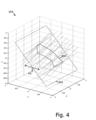
- the objective 132 of the optical transport system 114 and the objective 138 of the optical detection system 304 define an optical erecting unit 312 configured to image an oblique image plane of the sample 146. Due to the geometry of the optical erecting unit 310 the target area 400 is tilted as is shown in Figure 4 .
- the optical system 318 of the light sheet microscope 300 further comprises a light sheet illumination system 312, that is configured to form a light sheet for illuminating the sample 146 in an intermediate image space 116.
- Said light sheet illumination system 312 comprising a light sheet forming element 314, for example a cylindrical lens or a scanning element, and an illumination objective 316 configured to direct the light sheet into the intermediate image space 116.
- Figure 4 shows a schematic diagram of the sample space 104 of the light sheet microscope 300 according to Figure 3 .
- the plane 402 in the which the target area 400 is located is indicated by a dashed rectangle.
- the target area 400 are tilted with respect to the y axis.
- the whole plane in the which the target area 400 is located is moved along the x axis. This is indicated in Figure 4 by a double-headed arrow P3
- the scanning element 134 each time the scanning motion is completed, multiple target areas located in different planes arranged along the x axis in sequence are manipulated. Thus, a volume or stack formed by the target areas is manipulated.
- aspects have been described in the context of an apparatus, it is clear that these aspects also represent a description of the corresponding method, where a block or device corresponds to a method step or a feature of a method step. Analogously, aspects described in the context of a method step also represent a description of a corresponding block or item or feature of a corresponding apparatus.
Landscapes
- Physics & Mathematics (AREA)
- Chemical & Material Sciences (AREA)
- Analytical Chemistry (AREA)
- General Physics & Mathematics (AREA)
- Optics & Photonics (AREA)
- Engineering & Computer Science (AREA)
- Multimedia (AREA)
- Computer Vision & Pattern Recognition (AREA)
- General Engineering & Computer Science (AREA)
- Microscoopes, Condenser (AREA)
Claims (10)
- Microscope à feuille de lumière (100), comprenant :une source de lumière (106) configurée pour émettre une lumière d'éclairage,un système optique (108) configuré pour former une feuille de lumière à partir de la lumière d'éclairage dans un espace d'échantillon (104), ladite feuille de lumière étant focalisée dans une direction d'épaisseur perpendiculaire à une direction de propagation de la lumière de celle-ci pour former un col de faisceau dans ladite direction d'épaisseur,dans lequel le système optique (108) présente un diaphragme de champ (120) réglable pour faire varier une largeur de la feuille de lumière dans une direction de largeur perpendiculaire à la fois à la direction de propagation de la lumière et à la direction d'épaisseur,un élément de balayage (134) configuré pour déplacer la feuille de lumière d'une distance de balayage dans l'espace d'échantillon (104) le long d'une direction de balayage, etune unité de commande (110) configurée pour commander le diaphragme de champ (120) permettant de régler la largeur de la feuille de lumière et pour commander l'élément de balayage (134) permettant de déplacer la feuille de lumière de la distance de balayage afin de photo-manipuler une zone cible (200) d'un échantillon (146) par balayage de la zone cible (200) avec le col de faisceau de la feuille de lumière, ladite zone cible (200) étant définie par la largeur de la feuille de lumière et la distance de balayage.caractérisé en ce que,l'unité de commande (110) est configurée pour commander le diaphragme de champ (120) et l'élément de balayage (134) de sorte que la largeur de la feuille de lumière varie pendant que la feuille de lumière est déplacée le long de la direction de balayage.
- Microscope à feuille de lumière (100) selon la revendication 1, dans lequel le diaphragme de champ (120) est configuré pour régler une position d'une première extrémité de la largeur de la feuille de lumière et une position d'une seconde extrémité de la largeur de la feuille de lumière indépendamment l'une de l'autre.
- Microscope à feuille de lumière (100) selon l'une quelconque des revendications précédentes, dans lequel le système optique (108) est configuré pour former une image intermédiaire de la feuille de lumière dans un espace d'image intermédiaire (116), dans lequel le système optique (108, 302) comprend un système de transport optique (114) configuré pour imager l'image intermédiaire de la feuille de lumière à partir de l'espace d'image intermédiaire (116) dans l'espace d'échantillon (104).
- Microscope à feuille de lumière (100) selon la revendication 3, dans lequel le système de transport optique (114) comprend un premier objectif (132) faisant face à l'espace d'image intermédiaire (116), dans lequel le système optique (108) comprend un système de détection optique (136) permettant de détecter une lumière de détection émise par l'échantillon (146), ledit système de détection optique (136) présentant un détecteur (142) et un second objectif (138) faisant face à l'espace d'image intermédiaire (116), et dans lequel les axes optiques des premier et second objectifs (132,138) sont obliques l'un par rapport à l'autre.
- Microscope à feuille de lumière (100) selon la revendication 4, dans lequel le système optique (108) comprend un système d'éclairage optique (112) configuré pour former la feuille de lumière à partir de la lumière d'éclairage dans l'espace d'image intermédiaire (116), et dans lequel l'axe optique du second objectif (132) et l'axe optique du système d'éclairage optique (112) sont obliques l'un par rapport à l'autre.
- Microscope à feuille de lumière (100, 300) selon l'une quelconque des revendications précédentes, dans lequel le système optique (108, 318) comprend un objectif (122) faisant face à l'espace d'échantillon (104), et dans lequel l'angle d'ouverture dudit objectif présente une valeur entre 17° et 72°, en particulier entre 45° et 72°.
- Microscope à feuille de lumière (100, 300) selon l'une quelconque des revendications précédentes, dans lequel le système optique (108, 318) comprend un objectif unique (122) faisant face à l'espace d'échantillon (104).
- Microscope à feuille de lumière (100, 300) selon la revendication 7, dans lequel la zone cible (200, 400) est située dans un plan focal de l'objectif unique (122).
- Microscope à feuille de lumière (100, 300) selon l'une quelconque des revendications précédentes, dans lequel la source de lumière d'éclairage (106) et/ou la lumière de manipulation (302) comprennent un laser pulsé.
- Procédé de manipulation d'une zone cible (200) d'un échantillon (146) utilisant un microscope à feuille de lumière (100), comprenant les étapes suivantes :formation d'une feuille de lumière à partir d'une lumière d'éclairage dans un espace d'échantillon (104), ladite feuille de lumière étant focalisée dans une direction d'épaisseur perpendiculaire à une direction de propagation de la lumière de celle-ci pour former un col de faisceau dans ladite direction d'épaisseur, réglage de la largeur de la feuille de lumière, etdéplacement de la feuille de lumière d'une distance de balayage afin de photo-manipuler la zone cible (200, 400) de l'échantillon (146) par balayage de la zone cible (200, 400) avec le col de faisceau de la feuille de lumière, ladite zone cible (200, 400) étant définie par la largeur de la feuille de lumière et la distance de balayage,caractérisé en ce quela largeur de la feuille de lumière varie pendant que la feuille de lumière est déplacée le long de la direction de balayage.
Priority Applications (1)
| Application Number | Priority Date | Filing Date | Title |
|---|---|---|---|
| EP22204981.9A EP4163692A1 (fr) | 2020-03-31 | 2020-03-31 | Microscope à feuille de lumière et procédé de manipulation d'une zone cible d'un échantillon |
Applications Claiming Priority (1)
| Application Number | Priority Date | Filing Date | Title |
|---|---|---|---|
| PCT/EP2020/059130 WO2021197587A1 (fr) | 2020-03-31 | 2020-03-31 | Microscope à feuille de lumière et procédé de manipulation d'une zone cible d'un échantillon |
Related Child Applications (2)
| Application Number | Title | Priority Date | Filing Date |
|---|---|---|---|
| EP22204981.9A Division-Into EP4163692A1 (fr) | 2020-03-31 | 2020-03-31 | Microscope à feuille de lumière et procédé de manipulation d'une zone cible d'un échantillon |
| EP22204981.9A Division EP4163692A1 (fr) | 2020-03-31 | 2020-03-31 | Microscope à feuille de lumière et procédé de manipulation d'une zone cible d'un échantillon |
Publications (2)
| Publication Number | Publication Date |
|---|---|
| EP4127809A1 EP4127809A1 (fr) | 2023-02-08 |
| EP4127809B1 true EP4127809B1 (fr) | 2025-03-05 |
Family
ID=70391065
Family Applications (2)
| Application Number | Title | Priority Date | Filing Date |
|---|---|---|---|
| EP22204981.9A Withdrawn EP4163692A1 (fr) | 2020-03-31 | 2020-03-31 | Microscope à feuille de lumière et procédé de manipulation d'une zone cible d'un échantillon |
| EP20720741.6A Active EP4127809B1 (fr) | 2020-03-31 | 2020-03-31 | Microscope à feuille de lumière et procédé de manipulation d'une zone cible d'un échantillon |
Family Applications Before (1)
| Application Number | Title | Priority Date | Filing Date |
|---|---|---|---|
| EP22204981.9A Withdrawn EP4163692A1 (fr) | 2020-03-31 | 2020-03-31 | Microscope à feuille de lumière et procédé de manipulation d'une zone cible d'un échantillon |
Country Status (3)
| Country | Link |
|---|---|
| US (1) | US12449647B2 (fr) |
| EP (2) | EP4163692A1 (fr) |
| WO (1) | WO2021197587A1 (fr) |
Families Citing this family (1)
| Publication number | Priority date | Publication date | Assignee | Title |
|---|---|---|---|---|
| CN120065491A (zh) * | 2025-02-25 | 2025-05-30 | 华中科技大学 | 一种基于光场重构的可变倍单物镜光片显微系统 |
Family Cites Families (12)
| Publication number | Priority date | Publication date | Assignee | Title |
|---|---|---|---|---|
| DE102004016253B4 (de) * | 2004-04-02 | 2006-02-23 | Leica Microsystems Cms Gmbh | Rastermikroskop und Verfahren zur rastermikroskopischen Untersuchung einer Probe |
| DE102007047464B4 (de) | 2007-09-28 | 2023-03-02 | Carl Zeiss Microscopy Gmbh | Optische Anordnung zur Photomanipulation |
| DE102012214568A1 (de) * | 2012-08-16 | 2014-02-20 | Leica Microsystems Cms Gmbh | Optische Anordnung und ein Mikroskop |
| JP7180964B2 (ja) | 2014-01-17 | 2022-11-30 | ザ・トラスティーズ・オブ・コロンビア・ユニバーシティ・イン・ザ・シティ・オブ・ニューヨーク | 三次元イメージング装置および方法 |
| US10061111B2 (en) * | 2014-01-17 | 2018-08-28 | The Trustees Of Columbia University In The City Of New York | Systems and methods for three dimensional imaging |
| JP2017090851A (ja) | 2015-11-17 | 2017-05-25 | オリンパス株式会社 | シート照明顕微鏡、及び、シート照明方法 |
| DE102016103182B4 (de) * | 2016-02-23 | 2018-04-12 | Leica Microsystems Cms Gmbh | Lichtblattmikroskop und Verfahren zur lichtmikroskopischen Abbildung einer Probe |
| US11243391B2 (en) * | 2016-05-30 | 2022-02-08 | The Trustees Of Columbia University In The City Of New York | Three-dimensional imaging using swept confocally aligned planar excitation with asymmetrical magnification |
| DE102016119268B3 (de) | 2016-10-10 | 2017-12-21 | Leica Microsystems Cms Gmbh | Schiefebenenmikroskop |
| CN110178069B (zh) | 2016-11-12 | 2022-05-17 | 纽约市哥伦比亚大学理事会 | 显微镜设备、方法和系统 |
| JP2018169502A (ja) | 2017-03-30 | 2018-11-01 | オリンパス株式会社 | 顕微鏡装置 |
| US10768400B2 (en) * | 2017-04-24 | 2020-09-08 | Igor Lyuboshenko | Varying an illumination path of a selective plane illumination microscopy |
-
2020
- 2020-03-31 EP EP22204981.9A patent/EP4163692A1/fr not_active Withdrawn
- 2020-03-31 US US17/915,111 patent/US12449647B2/en active Active
- 2020-03-31 EP EP20720741.6A patent/EP4127809B1/fr active Active
- 2020-03-31 WO PCT/EP2020/059130 patent/WO2021197587A1/fr not_active Ceased
Also Published As
| Publication number | Publication date |
|---|---|
| US20230152562A1 (en) | 2023-05-18 |
| WO2021197587A1 (fr) | 2021-10-07 |
| EP4163692A1 (fr) | 2023-04-12 |
| US12449647B2 (en) | 2025-10-21 |
| EP4127809A1 (fr) | 2023-02-08 |
Similar Documents
| Publication | Publication Date | Title |
|---|---|---|
| KR102668960B1 (ko) | 자동 현미경 초점을 위한 시스템, 장치 및 방법 | |
| CN108604005B (zh) | 光片显微镜和用于样品的光学显微成像的方法 | |
| EP1857853B1 (fr) | Dispositif d'illumination | |
| US9030734B2 (en) | Scanning microscope, and method for light microscopy imaging of a specimen | |
| US8472113B2 (en) | Scanning microscope and method for light-microscopic imaging of an object | |
| CN109804293B (zh) | 斜面显微镜 | |
| EP1684109B1 (fr) | Appareil de traitement laser | |
| US7599115B2 (en) | Raster microscope | |
| US6813073B2 (en) | Light source for illumination in scanning microscopy, and scanning microscope | |
| CN111095073B (zh) | 在激光扫描显微镜中扫描激发辐射和/或操纵辐射的光学组件以及激光扫描显微镜 | |
| US11709137B2 (en) | Light sheet fluorescence microscope | |
| JP4820759B2 (ja) | 走査型顕微鏡 | |
| CN105283792A (zh) | 用于操作和成像显微样本的方法和光学布置 | |
| US9134523B2 (en) | Predictive focusing for image scanning systems | |
| JP2017523469A (ja) | 顕微鏡および微小試料の光学的な検査および/または操作のための方法 | |
| EP4127809B1 (fr) | Microscope à feuille de lumière et procédé de manipulation d'une zone cible d'un échantillon | |
| US9696532B2 (en) | Scanning laser microscope | |
| EP1959290A1 (fr) | Microscope laser | |
| US6680796B2 (en) | Microscope assemblage | |
| US20150253556A1 (en) | Confocal Incident-Light Scanning Microsope For Multipoint Scanning | |
| JP7086057B2 (ja) | 顕微鏡システム | |
| JP2010286799A (ja) | 走査型顕微鏡 | |
| JP4874012B2 (ja) | レーザ走査型顕微鏡およびレーザ走査型顕微鏡の画像取得方法 | |
| US20010028496A1 (en) | Method for aligning the optical beam path of a microscope, and microscope assemblage | |
| JP7505460B2 (ja) | 検出装置及び検出方法 |
Legal Events
| Date | Code | Title | Description |
|---|---|---|---|
| STAA | Information on the status of an ep patent application or granted ep patent |
Free format text: STATUS: UNKNOWN |
|
| STAA | Information on the status of an ep patent application or granted ep patent |
Free format text: STATUS: THE INTERNATIONAL PUBLICATION HAS BEEN MADE |
|
| PUAI | Public reference made under article 153(3) epc to a published international application that has entered the european phase |
Free format text: ORIGINAL CODE: 0009012 |
|
| STAA | Information on the status of an ep patent application or granted ep patent |
Free format text: STATUS: REQUEST FOR EXAMINATION WAS MADE |
|
| 17P | Request for examination filed |
Effective date: 20221007 |
|
| AK | Designated contracting states |
Kind code of ref document: A1 Designated state(s): AL AT BE BG CH CY CZ DE DK EE ES FI FR GB GR HR HU IE IS IT LI LT LU LV MC MK MT NL NO PL PT RO RS SE SI SK SM TR |
|
| P01 | Opt-out of the competence of the unified patent court (upc) registered |
Effective date: 20230414 |
|
| DAV | Request for validation of the european patent (deleted) | ||
| DAX | Request for extension of the european patent (deleted) | ||
| GRAP | Despatch of communication of intention to grant a patent |
Free format text: ORIGINAL CODE: EPIDOSNIGR1 |
|
| STAA | Information on the status of an ep patent application or granted ep patent |
Free format text: STATUS: GRANT OF PATENT IS INTENDED |
|
| INTG | Intention to grant announced |
Effective date: 20241004 |
|
| GRAS | Grant fee paid |
Free format text: ORIGINAL CODE: EPIDOSNIGR3 |
|
| GRAA | (expected) grant |
Free format text: ORIGINAL CODE: 0009210 |
|
| STAA | Information on the status of an ep patent application or granted ep patent |
Free format text: STATUS: THE PATENT HAS BEEN GRANTED |
|
| AK | Designated contracting states |
Kind code of ref document: B1 Designated state(s): AL AT BE BG CH CY CZ DE DK EE ES FI FR GB GR HR HU IE IS IT LI LT LU LV MC MK MT NL NO PL PT RO RS SE SI SK SM TR |
|
| REG | Reference to a national code |
Ref country code: GB Ref legal event code: FG4D |
|
| REG | Reference to a national code |
Ref country code: CH Ref legal event code: EP |
|
| REG | Reference to a national code |
Ref country code: IE Ref legal event code: FG4D |
|
| REG | Reference to a national code |
Ref country code: DE Ref legal event code: R096 Ref document number: 602020047175 Country of ref document: DE |
|
| PG25 | Lapsed in a contracting state [announced via postgrant information from national office to epo] |
Ref country code: RS Free format text: LAPSE BECAUSE OF FAILURE TO SUBMIT A TRANSLATION OF THE DESCRIPTION OR TO PAY THE FEE WITHIN THE PRESCRIBED TIME-LIMIT Effective date: 20250605 |
|
| PG25 | Lapsed in a contracting state [announced via postgrant information from national office to epo] |
Ref country code: FI Free format text: LAPSE BECAUSE OF FAILURE TO SUBMIT A TRANSLATION OF THE DESCRIPTION OR TO PAY THE FEE WITHIN THE PRESCRIBED TIME-LIMIT Effective date: 20250305 |
|
| REG | Reference to a national code |
Ref country code: NL Ref legal event code: MP Effective date: 20250305 |
|
| PG25 | Lapsed in a contracting state [announced via postgrant information from national office to epo] |
Ref country code: ES Free format text: LAPSE BECAUSE OF FAILURE TO SUBMIT A TRANSLATION OF THE DESCRIPTION OR TO PAY THE FEE WITHIN THE PRESCRIBED TIME-LIMIT Effective date: 20250305 |
|
| REG | Reference to a national code |
Ref country code: LT Ref legal event code: MG9D |
|
| PG25 | Lapsed in a contracting state [announced via postgrant information from national office to epo] |
Ref country code: NO Free format text: LAPSE BECAUSE OF FAILURE TO SUBMIT A TRANSLATION OF THE DESCRIPTION OR TO PAY THE FEE WITHIN THE PRESCRIBED TIME-LIMIT Effective date: 20250605 |
|
| PG25 | Lapsed in a contracting state [announced via postgrant information from national office to epo] |
Ref country code: HR Free format text: LAPSE BECAUSE OF FAILURE TO SUBMIT A TRANSLATION OF THE DESCRIPTION OR TO PAY THE FEE WITHIN THE PRESCRIBED TIME-LIMIT Effective date: 20250305 |
|
| PG25 | Lapsed in a contracting state [announced via postgrant information from national office to epo] |
Ref country code: LV Free format text: LAPSE BECAUSE OF FAILURE TO SUBMIT A TRANSLATION OF THE DESCRIPTION OR TO PAY THE FEE WITHIN THE PRESCRIBED TIME-LIMIT Effective date: 20250305 |
|
| PG25 | Lapsed in a contracting state [announced via postgrant information from national office to epo] |
Ref country code: GR Free format text: LAPSE BECAUSE OF FAILURE TO SUBMIT A TRANSLATION OF THE DESCRIPTION OR TO PAY THE FEE WITHIN THE PRESCRIBED TIME-LIMIT Effective date: 20250606 Ref country code: BG Free format text: LAPSE BECAUSE OF FAILURE TO SUBMIT A TRANSLATION OF THE DESCRIPTION OR TO PAY THE FEE WITHIN THE PRESCRIBED TIME-LIMIT Effective date: 20250305 |
|
| REG | Reference to a national code |
Ref country code: AT Ref legal event code: MK05 Ref document number: 1773417 Country of ref document: AT Kind code of ref document: T Effective date: 20250305 |
|
| PG25 | Lapsed in a contracting state [announced via postgrant information from national office to epo] |
Ref country code: NL Free format text: LAPSE BECAUSE OF FAILURE TO SUBMIT A TRANSLATION OF THE DESCRIPTION OR TO PAY THE FEE WITHIN THE PRESCRIBED TIME-LIMIT Effective date: 20250305 |
|
| PG25 | Lapsed in a contracting state [announced via postgrant information from national office to epo] |
Ref country code: SE Free format text: LAPSE BECAUSE OF FAILURE TO SUBMIT A TRANSLATION OF THE DESCRIPTION OR TO PAY THE FEE WITHIN THE PRESCRIBED TIME-LIMIT Effective date: 20250305 |
|
| PG25 | Lapsed in a contracting state [announced via postgrant information from national office to epo] |
Ref country code: SM Free format text: LAPSE BECAUSE OF FAILURE TO SUBMIT A TRANSLATION OF THE DESCRIPTION OR TO PAY THE FEE WITHIN THE PRESCRIBED TIME-LIMIT Effective date: 20250305 |
|
| PG25 | Lapsed in a contracting state [announced via postgrant information from national office to epo] |
Ref country code: PT Free format text: LAPSE BECAUSE OF FAILURE TO SUBMIT A TRANSLATION OF THE DESCRIPTION OR TO PAY THE FEE WITHIN THE PRESCRIBED TIME-LIMIT Effective date: 20250707 |
|
| PG25 | Lapsed in a contracting state [announced via postgrant information from national office to epo] |
Ref country code: IT Free format text: LAPSE BECAUSE OF FAILURE TO SUBMIT A TRANSLATION OF THE DESCRIPTION OR TO PAY THE FEE WITHIN THE PRESCRIBED TIME-LIMIT Effective date: 20250305 Ref country code: PL Free format text: LAPSE BECAUSE OF FAILURE TO SUBMIT A TRANSLATION OF THE DESCRIPTION OR TO PAY THE FEE WITHIN THE PRESCRIBED TIME-LIMIT Effective date: 20250305 |
|
| PG25 | Lapsed in a contracting state [announced via postgrant information from national office to epo] |
Ref country code: AT Free format text: LAPSE BECAUSE OF FAILURE TO SUBMIT A TRANSLATION OF THE DESCRIPTION OR TO PAY THE FEE WITHIN THE PRESCRIBED TIME-LIMIT Effective date: 20250305 |
|
| PG25 | Lapsed in a contracting state [announced via postgrant information from national office to epo] |
Ref country code: EE Free format text: LAPSE BECAUSE OF FAILURE TO SUBMIT A TRANSLATION OF THE DESCRIPTION OR TO PAY THE FEE WITHIN THE PRESCRIBED TIME-LIMIT Effective date: 20250305 Ref country code: CZ Free format text: LAPSE BECAUSE OF FAILURE TO SUBMIT A TRANSLATION OF THE DESCRIPTION OR TO PAY THE FEE WITHIN THE PRESCRIBED TIME-LIMIT Effective date: 20250305 |
|
| REG | Reference to a national code |
Ref country code: CH Ref legal event code: H13 Free format text: ST27 STATUS EVENT CODE: U-0-0-H10-H13 (AS PROVIDED BY THE NATIONAL OFFICE) Effective date: 20251023 |
|
| PG25 | Lapsed in a contracting state [announced via postgrant information from national office to epo] |
Ref country code: RO Free format text: LAPSE BECAUSE OF FAILURE TO SUBMIT A TRANSLATION OF THE DESCRIPTION OR TO PAY THE FEE WITHIN THE PRESCRIBED TIME-LIMIT Effective date: 20250305 |
|
| PG25 | Lapsed in a contracting state [announced via postgrant information from national office to epo] |
Ref country code: SK Free format text: LAPSE BECAUSE OF FAILURE TO SUBMIT A TRANSLATION OF THE DESCRIPTION OR TO PAY THE FEE WITHIN THE PRESCRIBED TIME-LIMIT Effective date: 20250305 |
|
| PG25 | Lapsed in a contracting state [announced via postgrant information from national office to epo] |
Ref country code: IS Free format text: LAPSE BECAUSE OF FAILURE TO SUBMIT A TRANSLATION OF THE DESCRIPTION OR TO PAY THE FEE WITHIN THE PRESCRIBED TIME-LIMIT Effective date: 20250705 |
|
| PG25 | Lapsed in a contracting state [announced via postgrant information from national office to epo] |
Ref country code: LU Free format text: LAPSE BECAUSE OF NON-PAYMENT OF DUE FEES Effective date: 20250331 |
|
| REG | Reference to a national code |
Ref country code: DE Ref legal event code: R097 Ref document number: 602020047175 Country of ref document: DE |
|
| REG | Reference to a national code |
Ref country code: BE Ref legal event code: MM Effective date: 20250331 |
|
| PG25 | Lapsed in a contracting state [announced via postgrant information from national office to epo] |
Ref country code: MC Free format text: LAPSE BECAUSE OF FAILURE TO SUBMIT A TRANSLATION OF THE DESCRIPTION OR TO PAY THE FEE WITHIN THE PRESCRIBED TIME-LIMIT Effective date: 20250305 |
|
| PLBE | No opposition filed within time limit |
Free format text: ORIGINAL CODE: 0009261 |
|
| STAA | Information on the status of an ep patent application or granted ep patent |
Free format text: STATUS: NO OPPOSITION FILED WITHIN TIME LIMIT |
|
| PG25 | Lapsed in a contracting state [announced via postgrant information from national office to epo] |
Ref country code: DK Free format text: LAPSE BECAUSE OF FAILURE TO SUBMIT A TRANSLATION OF THE DESCRIPTION OR TO PAY THE FEE WITHIN THE PRESCRIBED TIME-LIMIT Effective date: 20250305 |
|
| REG | Reference to a national code |
Ref country code: CH Ref legal event code: L10 Free format text: ST27 STATUS EVENT CODE: U-0-0-L10-L00 (AS PROVIDED BY THE NATIONAL OFFICE) Effective date: 20260114 |
|
| PG25 | Lapsed in a contracting state [announced via postgrant information from national office to epo] |
Ref country code: BE Free format text: LAPSE BECAUSE OF NON-PAYMENT OF DUE FEES Effective date: 20250331 |
|
| PG25 | Lapsed in a contracting state [announced via postgrant information from national office to epo] |
Ref country code: CH Free format text: LAPSE BECAUSE OF NON-PAYMENT OF DUE FEES Effective date: 20250331 |
|
| PG25 | Lapsed in a contracting state [announced via postgrant information from national office to epo] |
Ref country code: IE Free format text: LAPSE BECAUSE OF NON-PAYMENT OF DUE FEES Effective date: 20250331 |
|
| 26N | No opposition filed |
Effective date: 20251208 |
|
| PGFP | Annual fee paid to national office [announced via postgrant information from national office to epo] |
Ref country code: GB Payment date: 20260319 Year of fee payment: 7 |
|
| PGFP | Annual fee paid to national office [announced via postgrant information from national office to epo] |
Ref country code: DE Payment date: 20260320 Year of fee payment: 7 |
|
| PGFP | Annual fee paid to national office [announced via postgrant information from national office to epo] |
Ref country code: FR Payment date: 20260323 Year of fee payment: 7 |