EP4128732B1 - Suppression de résidu d'écho - Google Patents
Suppression de résidu d'écho Download PDFInfo
- Publication number
- EP4128732B1 EP4128732B1 EP21719331.7A EP21719331A EP4128732B1 EP 4128732 B1 EP4128732 B1 EP 4128732B1 EP 21719331 A EP21719331 A EP 21719331A EP 4128732 B1 EP4128732 B1 EP 4128732B1
- Authority
- EP
- European Patent Office
- Prior art keywords
- echo
- banded
- echo residual
- residual signal
- signal
- Prior art date
- Legal status (The legal status is an assumption and is not a legal conclusion. Google has not performed a legal analysis and makes no representation as to the accuracy of the status listed.)
- Active
Links
Images

Classifications
-
- H—ELECTRICITY
- H04—ELECTRIC COMMUNICATION TECHNIQUE
- H04M—TELEPHONIC COMMUNICATION
- H04M9/00—Arrangements for interconnection not involving centralised switching
- H04M9/08—Two-way loud-speaking telephone systems with means for conditioning the signal, e.g. for suppressing echoes for one or both directions of traffic
- H04M9/082—Two-way loud-speaking telephone systems with means for conditioning the signal, e.g. for suppressing echoes for one or both directions of traffic using echo cancellers
-
- G—PHYSICS
- G10—MUSICAL INSTRUMENTS; ACOUSTICS
- G10K—SOUND-PRODUCING DEVICES; METHODS OR DEVICES FOR PROTECTING AGAINST, OR FOR DAMPING, NOISE OR OTHER ACOUSTIC WAVES IN GENERAL; ACOUSTICS NOT OTHERWISE PROVIDED FOR
- G10K11/00—Methods or devices for transmitting, conducting or directing sound in general; Methods or devices for protecting against, or for damping, noise or other acoustic waves in general
- G10K11/16—Methods or devices for protecting against, or for damping, noise or other acoustic waves in general
- G10K11/175—Methods or devices for protecting against, or for damping, noise or other acoustic waves in general using interference effects; Masking sound
- G10K11/178—Methods or devices for protecting against, or for damping, noise or other acoustic waves in general using interference effects; Masking sound by electro-acoustically regenerating the original acoustic waves in anti-phase
- G10K11/1781—Methods or devices for protecting against, or for damping, noise or other acoustic waves in general using interference effects; Masking sound by electro-acoustically regenerating the original acoustic waves in anti-phase characterised by the analysis of input or output signals, e.g. frequency range, modes, transfer functions
- G10K11/17821—Methods or devices for protecting against, or for damping, noise or other acoustic waves in general using interference effects; Masking sound by electro-acoustically regenerating the original acoustic waves in anti-phase characterised by the analysis of input or output signals, e.g. frequency range, modes, transfer functions characterised by the analysis of the input signals only
- G10K11/17823—Reference signals, e.g. ambient acoustic environment
-
- G—PHYSICS
- G10—MUSICAL INSTRUMENTS; ACOUSTICS
- G10K—SOUND-PRODUCING DEVICES; METHODS OR DEVICES FOR PROTECTING AGAINST, OR FOR DAMPING, NOISE OR OTHER ACOUSTIC WAVES IN GENERAL; ACOUSTICS NOT OTHERWISE PROVIDED FOR
- G10K11/00—Methods or devices for transmitting, conducting or directing sound in general; Methods or devices for protecting against, or for damping, noise or other acoustic waves in general
- G10K11/16—Methods or devices for protecting against, or for damping, noise or other acoustic waves in general
- G10K11/175—Methods or devices for protecting against, or for damping, noise or other acoustic waves in general using interference effects; Masking sound
- G10K11/178—Methods or devices for protecting against, or for damping, noise or other acoustic waves in general using interference effects; Masking sound by electro-acoustically regenerating the original acoustic waves in anti-phase
- G10K11/1785—Methods, e.g. algorithms; Devices
- G10K11/17853—Methods, e.g. algorithms; Devices of the filter
- G10K11/17854—Methods, e.g. algorithms; Devices of the filter the filter being an adaptive filter
-
- H—ELECTRICITY
- H04—ELECTRIC COMMUNICATION TECHNIQUE
- H04B—TRANSMISSION
- H04B3/00—Line transmission systems
- H04B3/02—Details
- H04B3/20—Reducing echo effects or singing; Opening or closing transmitting path; Conditioning for transmission in one direction or the other
- H04B3/23—Reducing echo effects or singing; Opening or closing transmitting path; Conditioning for transmission in one direction or the other using a replica of transmitted signal in the time domain, e.g. echo cancellers
- H04B3/234—Reducing echo effects or singing; Opening or closing transmitting path; Conditioning for transmission in one direction or the other using a replica of transmitted signal in the time domain, e.g. echo cancellers using double talk detection
Definitions
- the present disclosure relates to audio processing, and in particular, to echo suppression.
- a telecommunications device such as an audio conferencing system generally includes both a loudspeaker and a microphone.
- the two parties in a communication may be referred to as the near end party and the far end party.
- the near end party is proximal to a first telecommunications device, and the far end party is at a different location than the near end party and communicates using a second telecommunications device via a wired or wireless telecommunications network.
- the microphone of the near end device captures not only the speech of the near end party, but may also capture the speech of the far end party that has been output from the loudspeaker at the near end.
- the output from the loudspeaker that is captured by the microphone is generally referred to as echo.
- the near end telecommunications device generally includes an echo management system for reducing the echo prior to transmitting the audio captured at the near end to the far end.
- the echo management system generally includes an echo cancellation system followed by an echo suppression system.
- the echo cancellation system is a linear system and typically may include an adaptive filter.
- the echo remaining in the audio signal after echo cancellation is generally referred to as the "echo residual".
- the echo suppression system is a nonlinear system that applies additional attenuation to the audio signal in order to reduce the echo residual.
- the attenuation performed by the echo suppression system is referred to as non-linear in that it may apply different gains to different frequencies or frequency bands.
- Telecommunications devices generally implement approximately an aggregate 50 dB of echo reduction based on the contributions of the physical echo return loss (e.g., due to the distance between the loudspeaker and the microphone), the echo cancellation and the echo suppression.
- EP1978649 discloses a spectral domain, non-linear echo cancellation method in a hands-free device.
- the system first estimates the echo residual power in each band of the input signal by modeling the power gain of the echo canceller for each band as a Gaussian distributed random variable, the mean and variance of which depend on the loopback power and a gain profile estimation. Next, the system estimates the statistical gain profile for each band and for each different input level. The system uses the statistical gain profile to quantize the input level into several segments. Next, the system models the wideband echo residual as a Gaussian mixture model, and calculates the likelihood of local talk. Finally, depending on the likelihood of local talk, the system applies different maximum suppressions to the bands of the input signal. Further details are provided below.
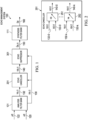
- FIG. 1 is a block diagram of an echo management system 100.
- the echo management system 100 generally removes echo from the audio captured by the near end device prior to transmission to the far end device. For example, when the audio from the far end is received by the near end device and is outputted by the loudspeaker of the near end device, the "echo" corresponds to this output from the loudspeaker that is captured by the microphone of the near end device.
- the echo management system 100 includes an analysis filter bank 101, an echo canceller 201, an echo suppressor 301, and a synthesis filter bank 111.
- the analysis filter bank 101 receives a reference signal 120 (also denoted as x(t)) and a captured signal 122 (also denoted as y(t)), performs a transform, and generates a transformed reference signal 130 (also denoted as X ( k , t ')) and a transformed captured signal 132 (also denoted as Y ( k , t ')).
- the reference signal 120 corresponds to the signal received from the far end device that is output by the loudspeaker of the near end device.
- the captured signal 122 corresponds to the audio captured by the microphone of the near end device, which may include local talk (e.g., the speech of a person associated with the near end device) as well as the echo of the output of the loudspeaker (e.g., the speech of a person associated with the far end device).
- local talk e.g., the speech of a person associated with the near end device
- the echo of the output of the loudspeaker e.g., the speech of a person associated with the far end device.
- the transform generally corresponds to transforming an input signal from one domain to another domain (e.g., a time domain to frequency domain transform).
- the analysis filter bank 101 performs filtering and decimation of the reference signal 120 and the captured signal 122 to generate the transformed reference signal 130 and the transformed captured signal 132.
- the analysis filter bank 101 performs filtering and decimation of x ( t ) to generate X(k, t'), where k indicates the sub-band filter index and t' indicates the new time variable after decimation.
- the analysis filter bank 101 performs filtering and decimation of y ( t ) to generate Y ( k , t ') .
- the parameter k may be adjusted as desired to adjust the fineness of the transform bins for a given input signal bandwidth.
- common bandwidths of the reference signal 120 may be 4 kHz, 8 kHz, 12 kHz, 16 kHz, 24 kHz, etc., with corresponding sampling rates of 8 kHz, 16 kHz, 24 kHz, 32 kHz, 48 kHz, etc.
- k may be 160 bins for a 4 kHz signal, 960 bins for a 24 kHz signal, etc. when performing the transform (e.g., a fast Fourier transform).
- the echo suppressor 301 receives the transformed reference signal 130 and the echo residual signal 140, performs echo suppression, and generates a modified echo residual signal 150 (also denoted as ⁇ ( k , t ')) .
- echo suppression refers to applying a non-linear attenuation to V(k, t') based on X(k, t') to generate the modified echo residual signal ⁇ ( k , t') as a suppressed signal. Further details of the echo suppressor 301 are provided with reference to FIG. 3 .
- Equation (1) x ⁇ ( t ) corresponds to the echo to be canceled out, h( t ) corresponds to a model of the speaker-room-microphone impulse response (of the room in which the near end device with the speaker and microphone is located), x ( t ) corresponds to the reference signal 120, and n ( t ) corresponds to noise.
- uplink voice e.g., no local talk at the near end, and the microphone captures only the echo of the loudspeaker output; uplink voice may also be referred to as near end voice
- y t h t ⁇ x t + n t
- the filter bank 101 is used to implement a sub-band adaptive filter to reduce the computation.
- FIG. 2 is a block diagram of the echo canceller 201 (see FIG. 1 ).
- the echo canceller 201 includes a plurality of adaptive filters (e.g., k adaptive filters) corresponding to the number of analysis bins. Two adaptive filters 251 and 252 are shown.
- the adaptive filter 251 receives X ( 0, t ') and Y ( 0, t '), applies an adaptive filter H 0 , and generates V ( 0 , t ').
- the adaptive filter 252 receives X(k, t') and Y ( k , t '), applies an adaptive filter H k , and generates V(k, t').
- the other adaptive filters in the echo canceller 201 that are not shown generate the remaining k - 1 components.
- X, Y, and V respectively correspond to the transformed reference signal 130, the transformed captured signal 132, and the echo residual signal 140 (see FIG. 1 ), with the signals corresponding to the respective bins being denoted with a suffix corresponding to the bin (e.g., "130-0" for the 0 -th bin of the reference signal 130, "130-k” for the k -th bin, etc.).
- the filter response H corresponds to the room impulse response h ( t ) in the transform domain.
- FIG. 3 is a block diagram of the echo suppressor 301 (see FIG. 1 ).
- an open-loop sub-band adaptive filter is a practical (but not an adequate) solution to cancel echo to the amount of 50 dB to enable a good experience of voice communication.
- full duplex communication e.g., double talk, when both ends are talking
- a nonlinear echo suppression can be applied after echo cancellation to further suppress echo but to allow the uplink voice of the near end party to interrupt the far end party.
- the third party (who is not the active two talkers in the duplex scenario) will have a bad experience if the suppressor lets through too much of the echo residual, even though the person being interrupted might not.
- a good suppressor shall suppress as much as possible of the echo residual while passing through as much as possible of the uplink voice. This goal is only possible, for a linear operation, by an adaptive filter such as the echo canceller 201.
- the echo suppressor 301 uses the intrinsic statistics of the echo residual to perform echo suppression.
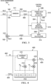
- the echo suppressor 301 includes a banding component 311, a power gain profile estimator 312, an echo residual estimator 313, a gain calculator 314, and a signal combiner 310.
- the banding component 311 receives the transformed reference signal 130 (also denoted as X ( k , t ')) and the echo residual signal 140 (also denoted as V ( k, t ')), performs frequency banding, and generates a banded reference signal 320 (also denoted as ( b , t ')) and a banded echo residual signal 322 (also denoted as ( b, t ')) .
- banding refers to grouping or aggregating multiple sub-bands or frequency bins of a signal to form a band, where the resulting number of bands is less than the original number of sub-bands or frequency bins.
- the banding may be performed by summing multiple sub-bands or frequency bins to form a band, and may include additional operations such as multiplication, absolute value calculation, magnitude calculation, etc.
- the banding component 311 may perform banding of the echo residual signal 140 to generate the banded echo residual signal 322 according to Equation (3):
- the banding component 311 may perform banding of the transformed reference signal 130 to generate the banded reference signal 320 according to Equation (4):
- X b , t ′ ⁇ k ⁇ B b X k , t ′ 2
- B ( b ) corresponds to a set of bins k that are associated with a band b, and the output of the banding corresponds to the signal power for each particular band.
- the banding may be equivalent rectangular bandwidth (ERB) banding, which corresponds to a psychoacoustic model of human hearing and associates larger bandwidths with lower frequencies.
- ERP rectangular bandwidth
- the number of bins k may be 960 bins
- the number of bands b may be 61
- each band b is associated with a number of the bins k, where more bins are associated with the lower frequency bands than with the higher frequency bands.
- the power gain profile estimator 312 receives the banded reference signal 320 and the banded echo residual signal 322, estimates a power gain profile, and generates an estimated power gain profile 324 and a loopback power 420 (also denoted as ( b , t '); see FIG. 4 ).
- the estimated power gain profile 324 corresponds to an estimate of the power gain profile of an acoustic echo canceller such as the echo canceller 201 (see FIG. 1 ).
- the power gain profile estimator 312 may also receive a control signal 326 that indicates the presence of double talk.
- Double talk refers to the situation of when both the far end party and the near end party are speaking at the same time (e.g., where the far end speech is indicated according to the reference signal 120 and the near end speech is indicated by the captured signal 122, which also includes the echo of the far end speech outputted by the loudspeaker and captured by the microphone at the near end).
- Equation (5) ⁇ ( k , t ) - H ( k, t ) is the error response of the adaptive filter not matching the real speaker-room-mic response. Notice that because ⁇ ( k , t ') depends on the input X ( k, t ), H ⁇ ( b , t ') will also depend on the input. And because the adaptive filter ⁇ ( k , t ) has multiple taps, the current residual power ( b , t' ) might not only depend on the current input power, but also on previous input power. In other words, echo residual V ( k, t ') will not be a linear time invariant (LTI) system output.
- LTI linear time invariant
- Equation (6) For simplicity and practical implementation, we model the power of the residual according to Equation (6):
- FIGS. 4-5 Additional details of the power gain profile estimator 312 are provided in FIGS. 4-5 .
- FIG. 4 is a block diagram of a loopback power calculator 400.
- the loopback power calculator 400 may be a component of the power gain profile estimator 312 (see FIG. 3 ).
- the loopback power calculator 400 generally calculates the loopback power 420 (also denoted as ( b , t '); see also FIG. 3 ) of the banded reference signal 320 (see FIG. 3 ; also denoted as ( b , t ')).
- the loopback power 420 corresponds to a weighted combination of historical values of the banded reference signal 320, as more fully detailed below.
- the loopback power calculator 400 includes a dominant adaptive filter tap finder 410, a memory 412, multipliers 414 and 416, and an adder 418.
- the dominant adaptive filter tap finder 410 receives filter coefficients 402 (corresponding to the filter coefficients of the adaptive filters H k in the echo canceller 201 of FIG. 2 ), determines the two dominant taps, and provides the weights w 0 and w 1 of the dominant taps to the multipliers 414 and 416.
- a dominant tap is a tap that provides a greater weight contribution to the adaptive filter than another tap.
- the dominant adaptive filter tap finder 410 uses the filter coefficients 402 corresponding to H k across all the sub-bands.
- the weights w 0 and w 1 may be relative weights.
- the memory 412 stores a history of the banded reference signal ( b , t ').
- the memory 412 has several memory elements, to store the current values of the banded reference signal ( b , t ') and one or more previous values of the banded reference signal ( b , t' - 1), ( b , t' - 2), ..., ( b , t' - n ).
- FIG. 2 shows the memory 412 containing 4 memory elements.
- the multiplier 414 multiplies one of the historical values of the banded reference signal 320 stored in the memory 412 by the weight w 0
- the multiplier 416 multiplies another of the historical values of the banded reference signal 320 stored in the memory 412 by the weight w 1
- the adder 418 adds the results of the multipliers 414 and 416.
- n 0 and n 1 are the delay indices respectively corresponding to the dominant taps w 0 and w 1 .
- n 0 is 2 and n 1 is 0.
- H ⁇ ( b , t ') When the input power is larger in a particular band (as corresponding to the loopback power ( b , t ')), H ⁇ ( b , t ') also tends to be larger in absolute value. This relationship is further detailed in FIG. 5 .
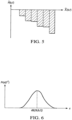
- FIG. 5 is a histogram of the relationship between the loopback power ( b , t ') (also referred to as the loopback power 420 in FIGS. 3-4 ) and the error (echo residual) transfer function H ⁇ ( b , t ') of the adaptive filter.
- H ⁇ ( b , t ') also tends to be larger in absolute value.
- H ⁇ ( b , t ') tends to be small as the noise will not be cancelled.
- the power gain profile estimator 312 uses the relationship of FIG. 5 as a histogram to estimate a gain profile for each band.
- the estimated power gain profile 324 may be represented as the mean ⁇ ( b , t' ) and variance ⁇ 2 ( b , t ') of H ⁇ ( b , t ') .
- the mean and variance are denoted as ⁇ b and ⁇ b 2 in the following paragraphs, for simplicity.
- the power gain profile estimator 312 uses the statistics of the echo residual signal (e.g., the echo residual signal 140) in combination with the history of the input signal (e.g., the reference signal 130) to estimate the power gain profile.
- the power gain profile estimator 312 uses the control signal 326 (e.g., the double talk indicator) to update the gain profile. Specifically, the power gain profile estimator 312 updates the gain profile only when it has confidence that there is no uplink (near end) voice, as indicated by the control signal 326.
- the control signal 326 may be generated in various ways, including by a double talk detector or using a stochastic method. An example of the stochastic method is to update the estimation at a random time once the reference signal has exceeded a first threshold for a duration longer than a second threshold.
- the echo residual estimator 313 receives the banded echo residual signal 322 (also denoted as ( b, t ')), the loopback power 420 (also denoted as ( b , t ')) and the estimated power gain profile 324 (the mean and variance of H ⁇ ( b , t '), denoted as ⁇ b and ⁇ b 2 ), and calculates an estimated echo residual power 328 (also denoted as ( b , t' )).
- the echo residual estimator 313 may calculate the estimate echo residual power 328 based on a combination of the estimated power gain profile 324 and the loopback power 420.
- the echo residual estimator 313 may calculate the estimate echo residual power 328 using a minimum operator applied to a combination of the banded echo residual signal 322, the loopback power 420 and the estimated power gain profile 324.
- the echo residual estimator 313 may calculate the estimated echo residual power 328 according to Equation (8):
- Equation (8) ⁇ is a factor determined by tuning.
- the minimum operator ensures that the estimated echo residual power 328 will never exceed V ( b, t '), which is a composite of the echo residual power and the local talk power.
- the estimated echo residual power 328 may be modeled as a Gaussian random variable with its centroid at ( b, t ') .
- the echo residual estimator 313 calculates the estimated echo residual power 328 according to the loopback power 420 for each band, by modeling the power gain of the echo canceller 201 (see FIGS. 1-2 ) for each band as a Gaussian random variable parameterized by the estimated power gain profile 324.
- the gain calculator 314 receives the banded echo residual signal 322 and the estimated echo residual power 328, and calculates banded gains 330 (also denoted as ( b , t ')).
- banded gains 330 also denoted as ( b , t ')
- One goal of calculating the banded gains 330 is to apply, to each particular band, different amounts of suppression for the half duplex scenario versus the full duplex scenario.
- the half duplex scenario describes when only one party is talking, e.g. either the near end or the far end.
- the full duplex scenario describes when both parties are talking, e.g. double talk.
- calculating the banded gains 330 includes selectively calculating the plurality of banded gains based on a likelihood of local talk in the echo residual signal.
- the gain calculator 314 calculates a feature to steer the gain calculation between the two scenarios.
- the estimated echo residual power 328 in dB has a Gaussian distribution with mean dB ⁇ ( b , t' ) ⁇ and variance ⁇ b 2 , which corresponds to the estimated power gain profile 324 calculated by the power gain profile estimator 312. It is also assumed that the estimated echo residual power 328 in dB has no cross-correlation (with the first assumption, independent) between bands.
- Equation (9) Pr x
- Equation (9) x is the estimated echo residual power 328 in dB, and ( b , t') corresponds to the centroid of the estimated echo residual power 328.
- FIG. 6 is a graph that illustrates the probability density function Pr( x
- the x-axis corresponds to x and the y-axis corresponds to Pr( x
- Equation (10) the log likelihood L of no uplink voice across all bands b is given by Equation (10):
- the log likelihood L is the sum over all bands b of the exponential component from Equation (9).
- the likelihood of local talk in the echo residual signal 140 is a log likelihood based on a mean and a variance of the estimated power gain profile summed over a plurality of frequency bands.
- the log likelihood L is calculated by modeling the echo residual signal 140 as a Gaussian mixture model applied over all the bands b.
- L ( E c ) When there is no uplink voice (e.g., no local talk captured by the device), L ( E c ) should be low; otherwise L ( E ) is high, and the log likelihood L of Equation (10) will be the signal to steer the gain calculation.
- Equation (11) G 0 is the gain in dB when there is uplink voice, and G 1 is the predefined gain in dB when there is no uplink voice.
- L th is a pre-defined threshold, which can be obtained for each device during initial setup via prior knowledge of whether local talk presents or not.
- calculating the banded gains 330 includes calculating a global maximum suppression gain G max across the plurality of frequency bands.
- the global maximum suppression gain is based on a first gain G 0 corresponding to a presence of the local talk, a second gain G 1 corresponding to an absence of the local talk, and the likelihood L of the local talk.
- the gain calculator 314 may calculate the gain for each band ( b , t') using one or more gain calculation processes.
- Example gain calculation processes that are suitable include the gain calculation processes described in U.S. Patent No. 9,173,025 , U.S. Patent No. 8,712,076 , and U.S. Patent No. 8,804,977 , which are incorporated herein by reference.
- the signal combiner 310 receives the echo residual signal 140 (also denoted as V(k, t')) and the banded gains 330 (also denoted as ( b , t ')) and generates a modified echo residual signal 150 (also denoted as ⁇ ( k , t ')) .
- the gain calculated for a given band b is applied to all of the sub-bands k that belong to that given ERB band.
- the signal combiner 310 may generate the modified echo residual signal 150 according to Equation (12):
- V ⁇ k , t ′ ⁇ k ⁇ B b G b , t ′ V k , t ′
- the echo residual signal 140 has a number of frequency bins k, where a given banded gain ( b , t ') of the banded gains 330 corresponds to a given frequency bin (e.g., each band b may be associated with a number of bins k ) , and generating the modified echo residual signal 150 includes, for each of the bins k of the echo residual signal 140, applying a corresponding banded gain ( b , t ') to generate the modified echo residual signal 150.
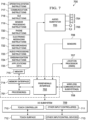
- FIG. 7 is a mobile device architecture 700 for implementing the features and processes described herein, according to an embodiment.
- the architecture 700 may be implemented in any electronic device, including but not limited to: a desktop computer, consumer audio/visual (AV) equipment, radio broadcast equipment, mobile devices (e.g., smartphone, tablet computer, laptop computer, wearable device), etc..
- AV consumer audio/visual
- the architecture 700 is for a laptop computer and includes processor(s) 701, peripherals interface 702, audio subsystem 703, loudspeakers 704, microphone 705, sensors 706 (e.g., accelerometers, gyros, barometer, magnetometer, camera), location processor 707 (e.g., GNSS receiver), wireless communications subsystems 708 (e.g., Wi-Fi, Bluetooth, cellular) and I/O subsystem(s) 709, which includes touch controller 710 and other input controllers 711, touch surface 712 and other input/control devices 713.
- Memory interface 714 is coupled to processors 701, peripherals interface 702 and memory 715 (e.g., flash, RAM, ROM).
- Memory 715 stores computer program instructions and data, including but not limited to: operating system instructions 716, communication instructions 717, GUI instructions 718, sensor processing instructions 719, phone instructions 720, electronic messaging instructions 721, web browsing instructions 722, audio processing instructions 723, GNSS/navigation instructions 724 and applications/data 725.
- Audio processing instructions 723 include instructions for performing the audio processing described herein.
- FIG. 8 is a flowchart of a method 800 of audio processing.
- the method 800 may be performed by a device (e.g., a laptop computer, a mobile telephone, etc.) with the components of the architecture 700 of FIG. 7 , to implement the functionality of the echo management system 100 (see FIG. 1 ), the echo canceller 201 (see FIG. 2 ), the echo suppressor 301 (see FIG. 3 ), the loopback power calculator 400 (see FIG. 4 ), etc., for example by executing one or more computer programs.
- a device e.g., a laptop computer, a mobile telephone, etc.
- the components of the architecture 700 of FIG. 7 to implement the functionality of the echo management system 100 (see FIG. 1 ), the echo canceller 201 (see FIG. 2 ), the echo suppressor 301 (see FIG. 3 ), the loopback power calculator 400 (see FIG. 4 ), etc., for example by executing one or more computer programs.
- a reference signal and an echo residual signal are received.
- the echo suppressor 301 may receive the transformed reference signal 130 and the echo residual signal 140.
- the transformed reference signal 130 corresponds to the reference signal 120, as can be seen in FIG. 1 .
- a banded reference signal and a banded echo residual signal are generated by performing frequency banding on the reference signal and the echo residual signal.
- the banding component 311 may perform banding on the transformed reference signal 130 and the echo residual signal 140 to generate the banded reference signal 320 and the banded echo residual signal 322, respectively.
- an estimated power gain profile and a loopback power are calculated based on the banded reference signal and the banded echo residual signal.
- the estimated power gain profile 324 corresponds to an estimate of the power gain profile of an acoustic echo canceller such as the echo canceller 201 (see FIG. 1 ).
- the power gain profile estimator 312 may calculate the estimated power gain profile 324 based on the banded reference signal 320 and the banded echo residual signal 322.
- the loopback power calculator 400 (see FIG. 4 ) may calculate the loopback power 420 based on the banded reference signal 320.
- the estimated power gain profile 324 may indicate a long-term amount of echo cancellation as calculated by the loopback power calculator 400, e.g. by using the history of the banded reference signal 320 stored in the memory 412.
- an estimated echo residual power is calculated based on the banded echo residual signal, the loopback power and the estimated power gain profile.
- the echo residual estimator 313 may calculate the estimated echo residual power 328 based on the banded echo residual signal 322, the loopback power 420 and the estimated power gain profile 324.
- a plurality of banded gains are calculated based on the banded echo residual signal and the estimated echo residual power.
- the gain calculator 314 may calculate the banded gains 330 based on the banded echo residual signal 322 and the estimated echo residual power 328.
- a modified echo residual signal is generated by applying the plurality of banded gains to the echo residual signal.
- the signal combiner 310 may generate the modified echo residual signal 150 by applying the banded gains 330 to the echo residual signal 140.
- the method 800 may include additional steps corresponding to the other functionalities of the echo management system 100, the echo canceller 201, the echo suppressor 301, the loopback power calculator 400, etc. as described herein.
- the reference signal may be outputted by a loudspeaker, such as the loudspeakers 704 (see FIG. 7 ).
- near end audio may be captured by a microphone (e.g., the microphone 705 of FIG. 5 ), a near end audio signal may be generated, and the echo residual signal may be generated by performing echo cancellation on the near end audio signal (e.g., by the echo canceller 201 of FIG. 1 ).
- the near end audio may include local talk (e.g., speech generated by the near end person), echo (e.g., the far end speech outputted by the loudspeaker at the near end), etc.
- the modified echo residual may be transmitted by the near end device to a far end device, e.g. as part of a teleconference, a videoconference, etc.
- An embodiment may be implemented in hardware, executable modules stored on a computer readable medium, or a combination of both (e.g., programmable logic arrays). Unless otherwise specified, the steps executed by embodiments need not inherently be related to any particular computer or other apparatus, although they may be in certain embodiments. In particular, various general-purpose machines may be used with programs written in accordance with the teachings herein, or it may be more convenient to construct more specialized apparatus (e.g., integrated circuits) to perform the required method steps.
- embodiments may be implemented in one or more computer programs executing on one or more programmable computer systems each comprising at least one processor, at least one data storage system (including volatile and non-volatile memory and/or storage elements), at least one input device or port, and at least one output device or port.
- Program code is applied to input data to perform the functions described herein and generate output information.
- the output information is applied to one or more output devices, in known fashion.
- Each such computer program is preferably stored on or downloaded to a storage media or device (e.g., solid state memory or media, or magnetic or optical media) readable by a general or special purpose programmable computer, for configuring and operating the computer when the storage media or device is read by the computer system to perform the procedures described herein.
- a storage media or device e.g., solid state memory or media, or magnetic or optical media
- the inventive system may also be considered to be implemented as a computer-readable storage medium, configured with a computer program, where the storage medium so configured causes a computer system to operate in a specific and predefined manner to perform the functions described herein. (Software per se and intangible or transitory signals are excluded to the extent that they are unpatentable subject matter.)
- Portions of the adaptive audio system may include one or more networks that comprise any desired number of individual machines, including one or more routers (not shown) that serve to buffer and route the data transmitted among the computers.
- Such a network may be built on various different network protocols, and may be the Internet, a Wide Area Network (WAN), a Local Area Network (LAN), or any combination thereof.
- One or more of the components, blocks, processes or other functional components may be implemented through a computer program that controls execution of a processor-based computing device of the system. It should also be noted that the various functions disclosed herein may be described using any number of combinations of hardware, firmware, and/or as data and/or instructions embodied in various machine-readable or computer-readable media, in terms of their behavioral, register transfer, logic component, and/or other characteristics.
- Computer-readable media in which such formatted data and/or instructions may be embodied include, but are not limited to, physical (non-transitory), non-volatile storage media in various forms, such as optical, magnetic or semiconductor storage media.
Landscapes
- Engineering & Computer Science (AREA)
- Signal Processing (AREA)
- Physics & Mathematics (AREA)
- Acoustics & Sound (AREA)
- Multimedia (AREA)
- Computer Networks & Wireless Communication (AREA)
- Cable Transmission Systems, Equalization Of Radio And Reduction Of Echo (AREA)
- Telephone Function (AREA)
Claims (15)
- Procédé mis en oeuvre par ordinateur de traitement audio, le procédé comprenant :la réception (802) d'un signal de référence (130) et d'un signal résiduel d'écho (140) ;la génération (804) d'un signal de référence en bandes (320) et d'un signal résiduel d'écho en bandes (322) en réalisant une répartition de fréquence respectivement sur le signal de référence et le signal résiduel d'écho ;le calcul (806) d'un profil de gain de puissance estimé (324) d'un annuleur d'écho acoustique (201) et d'une puissance de bouclage (420), dans lequel la puissance de bouclage correspond à une combinaison pondérée de valeurs de puissance historiques du signal de référence en bandes, le profil de gain de puissance estimé est calculé à l'aide de statistiques du signal résiduel d'écho en bandes en combinaison avec les valeurs de puissance historiques du signal de référence en bandes ;le calcul (808) d'une puissance résiduelle d'écho estimée (328) pour chaque bande sur la base du signal résiduel d'écho en bandes, de la puissance de bouclage et du profil de gain de puissance estimé ;le calcul (810) d'une pluralité de gains en bandes (330) sur la base du signal résiduel d'écho en bandes et de la puissance résiduelle d'écho estimée ; etla génération (812) d'un signal résiduel d'écho modifié (150) en appliquant la pluralité de gains en bandes au signal résiduel d'écho.
- Procédé selon la revendication 1, comprenant en outre :
la délivrance, par un haut-parleur, du signal de référence. - Procédé selon l'une quelconque des revendications 1-2, comprenant en outre :la capture, par un microphone, de l'audio d'extrémité proche ;la génération d'un signal audio d'extrémité proche correspondant à l'audio d'extrémité proche ; etla génération du signal résiduel d'écho en réalisant une annulation d'écho sur le signal audio d'extrémité proche.
- Procédé selon l'une quelconque des revendications 1-3 comprenant en outre :
la transmission, à un dispositif d'extrémité distante, du signal résiduel d'écho modifié. - Procédé selon l'une quelconque des revendications 1-4, dans lequel le signal résiduel d'écho présente une pluralité de groupes de fréquences, dans lequel le signal résiduel d'écho en bandes présente une pluralité de bandes de fréquences, et dans lequel la génération du signal résiduel d'écho en bandes comprend :
la génération du signal résiduel d'écho en bandes en réalisant une répartition de bande passante rectangulaire équivalente sur le signal résiduel d'écho, dans lequel la répartition rectangulaire équivalente regroupe la pluralité de groupes de fréquences dans la pluralité de bandes de fréquences selon un modèle psychoacoustique d'audition humaine. - Procédé selon l'une quelconque des revendications 1-5, dans lequel le calcul du profil de gain de puissance estimé inclut :pour chacun d'une pluralité de filtres adaptatifs, le calcul, par un chercheur de prises de filtres adaptatifs dominantes, de deux prises dominantes, dans lequel la pluralité de filtres adaptatifs correspond au nombre de groupes d'analyse du signal de référence (130) et chacun de la pluralité de filtres adaptatifs reçoit le signal de référence (130) et un signal capturé transformé (132) qui correspondent aux groupes respectifs et génèrent le signal résiduel d'écho (140) correspondant aux groupes respectifs, dans lequel les prises dominantes fournissent une plus grande contribution pondérale à un filtre adaptatif actuel de la pluralité de filtres adaptatifs par rapport à d'autres prises du filtre adaptatif actuel de la pluralité de filtres adaptatifs ;le calcul de la puissance de bouclage du signal de référence en bandes à l'aide des deux prises dominantes et des valeurs de puissance historiques du signal de référence en bandes ; etle calcul du profil de gain de puissance estimé à l'aide un histogramme basé sur le signal de référence en bandes.
- Procédé selon la revendication 6, dans lequel le profil de gain de puissance estimé inclut une moyenne et une variance.
- Procédé selon l'une quelconque des revendications 1-7, dans lequel la puissance de bouclage est calculée sur une pluralité de bandes formées par la répartition de fréquence sur le signal de référence et le signal résiduel d'écho, dans lequel le calcul de la puissance résiduelle d'écho estimée inclut :
le calcul de la puissance résiduelle d'écho estimée selon la puissance de bouclage pour chaque bande de la pluralité de bandes en modélisant le gain de puissance d'un annuleur d'écho pour chaque bande en tant que variable aléatoire gaussienne paramétrée par le profil de gain de puissance estimé. - Procédé selon l'une quelconque des revendications 1-8, dans lequel le calcul de la pluralité de gains en bandes inclut le calcul sélectif de la pluralité de gains en bandes sur la base d'une vraisemblance de conversation locale dans le signal résiduel d'écho, dans lequel la conversation locale correspond à de l'audio capturé par un dispositif qui met en oeuvre le procédé selon l'une quelconque des revendications 1-5.
- Procédé selon la revendication 9, dans lequel la vraisemblance de conversation locale dans le signal résiduel d'écho est soit :calculée en modélisant le signal résiduel d'écho en tant que modèle de mélange gaussien appliqué sur une pluralité de bandes formées par la répartition de fréquence sur le signal de référence et le signal résiduel d'écho ; soitune vraisemblance logarithmique basée sur une moyenne et une variance du profil de gain de puissance estimé additionnées sur une pluralité de bandes de fréquences formées par la répartition de fréquence sur le signal de référence et le signal résiduel d'écho.
- Procédé selon la revendication 9, dans lequel le calcul de la pluralité de gains en bandes inclut le calcul d'un gain de suppression maximal global sur la pluralité de bandes de fréquences.
- Procédé selon la revendication 11, dans lequel le calcul du gain de suppression maximal global est basé sur un premier gain correspondant à une présence de la conversation locale, un second gain correspondant à une absence de la conversation locale, et la vraisemblance de la conversation locale.
- Procédé selon l'une quelconque des revendications 1-12, dans lequel le signal résiduel d'écho présente une pluralité de groupes de fréquences, dans lequel un gain en bandes donné de la pluralité de gains en bandes correspond à un groupe de fréquences donné de la pluralité de groupes de fréquences, et dans lequel la génération du signal résiduel d'écho modifié inclut :
pour chacun de la pluralité de groupes de fréquence du signal résiduel d'écho, l'application d'un gain en bandes correspondant de la pluralité de gains en bandes pour générer le signal résiduel d'écho modifié. - Support non transitoire lisible par ordinateur stockant un programme informatique qui, lorsqu'il est exécuté par un processeur, commande un appareil pour exécuter un traitement incluant le procédé selon l'une quelconque des revendications 1-13.
- Appareil de traitement audio, l'appareil comprenant :un processeur,dans lequel le processeur est configuré pour commander l'appareil pour réaliser le procédé selon l'une quelconque des revendications 1-13.
Applications Claiming Priority (3)
| Application Number | Priority Date | Filing Date | Title |
|---|---|---|---|
| US202062993149P | 2020-03-23 | 2020-03-23 | |
| US202163153523P | 2021-02-25 | 2021-02-25 | |
| PCT/US2021/023059 WO2021194859A1 (fr) | 2020-03-23 | 2021-03-19 | Suppression de résidu d'écho |
Publications (2)
| Publication Number | Publication Date |
|---|---|
| EP4128732A1 EP4128732A1 (fr) | 2023-02-08 |
| EP4128732B1 true EP4128732B1 (fr) | 2024-09-04 |
Family
ID=75539919
Family Applications (1)
| Application Number | Title | Priority Date | Filing Date |
|---|---|---|---|
| EP21719331.7A Active EP4128732B1 (fr) | 2020-03-23 | 2021-03-19 | Suppression de résidu d'écho |
Country Status (8)
| Country | Link |
|---|---|
| US (1) | US12231603B2 (fr) |
| EP (1) | EP4128732B1 (fr) |
| JP (1) | JP2023519249A (fr) |
| KR (1) | KR20220157475A (fr) |
| CN (1) | CN115315935A (fr) |
| BR (1) | BR112022018422A2 (fr) |
| ES (1) | ES2991393T3 (fr) |
| WO (1) | WO2021194859A1 (fr) |
Families Citing this family (5)
| Publication number | Priority date | Publication date | Assignee | Title |
|---|---|---|---|---|
| CN115349250A (zh) * | 2020-03-23 | 2022-11-15 | 杜比实验室特许公司 | 采用上采样的双端讲话检测 |
| CN115315935A (zh) * | 2020-03-23 | 2022-11-08 | 杜比实验室特许公司 | 回声残余抑制 |
| CN114333749B (zh) | 2020-09-30 | 2025-07-15 | 腾讯科技(深圳)有限公司 | 啸叫抑制方法、装置、计算机设备和存储介质 |
| KR20240070586A (ko) * | 2021-09-30 | 2024-05-21 | 돌비 레버러토리즈 라이쎈싱 코오포레이션 | 음향 에코 제거를 위한 강인한 전경/배경 필터링 제어 |
| KR102927481B1 (ko) | 2025-06-09 | 2026-02-19 | 주식회사 에이알이 | 원거리 음향전달함수 모델예측에 기반한 실외환경 능동소음제어 장치 및 방법 |
Family Cites Families (23)
| Publication number | Priority date | Publication date | Assignee | Title |
|---|---|---|---|---|
| US6163608A (en) | 1998-01-09 | 2000-12-19 | Ericsson Inc. | Methods and apparatus for providing comfort noise in communications systems |
| FR2908003B1 (fr) | 2006-10-26 | 2009-04-03 | Parrot Sa | Procede de reduction de l'echo acoustique residuel apres supression d'echo dans un dispositif"mains libres" |
| GB2448201A (en) | 2007-04-04 | 2008-10-08 | Zarlink Semiconductor Inc | Cancelling non-linear echo during full duplex communication in a hands free communication system. |
| DE102008039330A1 (de) | 2008-01-31 | 2009-08-13 | Fraunhofer-Gesellschaft zur Förderung der angewandten Forschung e.V. | Vorrichtung und Verfahren zum Berechnen von Filterkoeffizienten zur Echounterdrückung |
| US9336785B2 (en) * | 2008-05-12 | 2016-05-10 | Broadcom Corporation | Compression for speech intelligibility enhancement |
| ES2558559T3 (es) | 2011-02-03 | 2016-02-05 | Telefonaktiebolaget L M Ericsson (Publ) | Estimación y supresión de no linealidades de altavoces armónicos |
| EP2673777B1 (fr) * | 2011-02-10 | 2018-12-26 | Dolby Laboratories Licensing Corporation | Suppression de bruit combinée et signaux hors emplacement |
| US8804977B2 (en) | 2011-03-18 | 2014-08-12 | Dolby Laboratories Licensing Corporation | Nonlinear reference signal processing for echo suppression |
| US9173025B2 (en) | 2012-02-08 | 2015-10-27 | Dolby Laboratories Licensing Corporation | Combined suppression of noise, echo, and out-of-location signals |
| US8712076B2 (en) | 2012-02-08 | 2014-04-29 | Dolby Laboratories Licensing Corporation | Post-processing including median filtering of noise suppression gains |
| US9338551B2 (en) | 2013-03-15 | 2016-05-10 | Broadcom Corporation | Multi-microphone source tracking and noise suppression |
| US9185506B1 (en) | 2013-12-16 | 2015-11-10 | Amazon Technologies, Inc. | Comfort noise generation based on noise estimation |
| US9503815B2 (en) | 2014-05-28 | 2016-11-22 | Apple Inc. | Perceptual echo gate approach and design for improved echo control to support higher audio and conversational quality |
| US9363600B2 (en) | 2014-05-28 | 2016-06-07 | Apple Inc. | Method and apparatus for improved residual echo suppression and flexible tradeoffs in near-end distortion and echo reduction |
| US10477031B2 (en) | 2015-12-08 | 2019-11-12 | Nuance Communications, Inc. | System and method for suppression of non-linear acoustic echoes |
| KR20170142001A (ko) | 2016-06-16 | 2017-12-27 | 삼성전자주식회사 | 전자 장치, 그의 반향 신호 제거 방법 및 비일시적 컴퓨터 판독가능 기록매체 |
| US10382092B2 (en) | 2017-11-27 | 2019-08-13 | Verizon Patent And Licensing Inc. | Method and system for full duplex enhanced audio |
| US10115411B1 (en) | 2017-11-27 | 2018-10-30 | Amazon Technologies, Inc. | Methods for suppressing residual echo |
| EP3785259B1 (fr) * | 2018-04-27 | 2022-11-30 | Dolby Laboratories Licensing Corporation | Estimation de bruit de fond utilisant la confiance d'écart |
| EP4224833A3 (fr) | 2018-05-09 | 2023-10-11 | Nureva Inc. | Procédé et appareil utilisant des informations d'estimation d'écho résiduel pour déduire des paramètres de réduction d'écho secondaire |
| US10602270B1 (en) * | 2018-11-30 | 2020-03-24 | Microsoft Technology Licensing, Llc | Similarity measure assisted adaptation control |
| CN111835383B (zh) * | 2019-04-17 | 2022-04-01 | 达发科技(苏州)有限公司 | 回音与近端串扰消除系统 |
| CN115315935A (zh) * | 2020-03-23 | 2022-11-08 | 杜比实验室特许公司 | 回声残余抑制 |
-
2021
- 2021-03-19 CN CN202180023584.2A patent/CN115315935A/zh active Pending
- 2021-03-19 ES ES21719331T patent/ES2991393T3/es active Active
- 2021-03-19 US US17/911,529 patent/US12231603B2/en active Active
- 2021-03-19 KR KR1020227036773A patent/KR20220157475A/ko not_active Ceased
- 2021-03-19 BR BR112022018422A patent/BR112022018422A2/pt unknown
- 2021-03-19 WO PCT/US2021/023059 patent/WO2021194859A1/fr not_active Ceased
- 2021-03-19 EP EP21719331.7A patent/EP4128732B1/fr active Active
- 2021-03-19 JP JP2022557771A patent/JP2023519249A/ja active Pending
Also Published As
| Publication number | Publication date |
|---|---|
| WO2021194859A1 (fr) | 2021-09-30 |
| BR112022018422A2 (pt) | 2022-10-25 |
| KR20220157475A (ko) | 2022-11-29 |
| US20230138637A1 (en) | 2023-05-04 |
| CN115315935A (zh) | 2022-11-08 |
| EP4128732A1 (fr) | 2023-02-08 |
| JP2023519249A (ja) | 2023-05-10 |
| ES2991393T3 (es) | 2024-12-03 |
| US12231603B2 (en) | 2025-02-18 |
Similar Documents
| Publication | Publication Date | Title |
|---|---|---|
| EP4128732B1 (fr) | Suppression de résidu d'écho | |
| US8675883B2 (en) | Apparatus and associated methodology for suppressing an acoustic echo | |
| CN108141502B (zh) | 降低声学系统中的声学反馈的方法及音频信号处理设备 | |
| EP2749016B1 (fr) | Traitement de signaux audio | |
| CN111341336B (zh) | 一种回声消除方法、装置、终端设备及介质 | |
| US7062040B2 (en) | Suppression of echo signals and the like | |
| US10477031B2 (en) | System and method for suppression of non-linear acoustic echoes | |
| CN111031448B (zh) | 回声消除方法、装置、电子设备和存储介质 | |
| EP2700161B1 (fr) | Traitement de signaux audio | |
| KR20010071860A (ko) | 디지털 적응형 필터 및 이를 사용하는 반향 제거기 | |
| KR102190833B1 (ko) | 에코 억제 | |
| KR20160076059A (ko) | 디스플레이장치 및 그 반향 제거방법 | |
| CN113744748A (zh) | 一种网络模型的训练方法、回声消除方法及设备 | |
| EP3469591B1 (fr) | Gestion et estimation d'écho avec adaptation d'un ensemble de filtre de prédiction éparse | |
| US9123324B2 (en) | Non-linear post-processing control in stereo acoustic echo cancellation | |
| EP2930917A1 (fr) | Procédé et appareil pour mettre à jour des coefficients de filtre d'un annuleur d'écho adaptatif | |
| EP2716023B1 (fr) | Commande de taille de pas d'adaptation et de gain de suppression dans la régulation d'écho acoustique | |
| EP2663979B1 (fr) | Traitement de signaux audio | |
| US6694020B1 (en) | Frequency domain stereophonic acoustic echo canceller utilizing non-linear transformations | |
| RU2834267C1 (ru) | Подавление остаточного эхо | |
| CN112489669A (zh) | 一种音频信号处理方法、装置、设备和介质 | |
| CN116962583B (zh) | 一种回声控制的方法、装置、设备、存储介质及程序产品 | |
| JP6356087B2 (ja) | エコー消去装置、その方法及びプログラム | |
| EP4205376B1 (fr) | Dispositif de traitement acoustique pour l'annulation d'echo acoustique mimo | |
| CN119832923A (zh) | 音频回声处理方法、装置、设备、存储介质以及程序产品 |
Legal Events
| Date | Code | Title | Description |
|---|---|---|---|
| STAA | Information on the status of an ep patent application or granted ep patent |
Free format text: STATUS: UNKNOWN |
|
| STAA | Information on the status of an ep patent application or granted ep patent |
Free format text: STATUS: THE INTERNATIONAL PUBLICATION HAS BEEN MADE |
|
| PUAI | Public reference made under article 153(3) epc to a published international application that has entered the european phase |
Free format text: ORIGINAL CODE: 0009012 |
|
| STAA | Information on the status of an ep patent application or granted ep patent |
Free format text: STATUS: REQUEST FOR EXAMINATION WAS MADE |
|
| 17P | Request for examination filed |
Effective date: 20220914 |
|
| AK | Designated contracting states |
Kind code of ref document: A1 Designated state(s): AL AT BE BG CH CY CZ DE DK EE ES FI FR GB GR HR HU IE IS IT LI LT LU LV MC MK MT NL NO PL PT RO RS SE SI SK SM TR |
|
| RAP3 | Party data changed (applicant data changed or rights of an application transferred) |
Owner name: DOLBY LABORATORIES LICENSING CORPORATION |
|
| P01 | Opt-out of the competence of the unified patent court (upc) registered |
Effective date: 20230417 |
|
| DAV | Request for validation of the european patent (deleted) | ||
| DAX | Request for extension of the european patent (deleted) | ||
| GRAP | Despatch of communication of intention to grant a patent |
Free format text: ORIGINAL CODE: EPIDOSNIGR1 |
|
| STAA | Information on the status of an ep patent application or granted ep patent |
Free format text: STATUS: GRANT OF PATENT IS INTENDED |
|
| INTG | Intention to grant announced |
Effective date: 20240404 |
|
| GRAS | Grant fee paid |
Free format text: ORIGINAL CODE: EPIDOSNIGR3 |
|
| GRAA | (expected) grant |
Free format text: ORIGINAL CODE: 0009210 |
|
| STAA | Information on the status of an ep patent application or granted ep patent |
Free format text: STATUS: THE PATENT HAS BEEN GRANTED |
|
| AK | Designated contracting states |
Kind code of ref document: B1 Designated state(s): AL AT BE BG CH CY CZ DE DK EE ES FI FR GB GR HR HU IE IS IT LI LT LU LV MC MK MT NL NO PL PT RO RS SE SI SK SM TR |
|
| REG | Reference to a national code |
Ref country code: GB Ref legal event code: FG4D |
|
| REG | Reference to a national code |
Ref country code: CH Ref legal event code: EP |
|
| REG | Reference to a national code |
Ref country code: IE Ref legal event code: FG4D |
|
| REG | Reference to a national code |
Ref country code: DE Ref legal event code: R096 Ref document number: 602021018300 Country of ref document: DE |
|
| REG | Reference to a national code |
Ref country code: NL Ref legal event code: FP |
|
| REG | Reference to a national code |
Ref country code: ES Ref legal event code: FG2A Ref document number: 2991393 Country of ref document: ES Kind code of ref document: T3 Effective date: 20241203 |
|
| REG | Reference to a national code |
Ref country code: LT Ref legal event code: MG9D |
|
| PG25 | Lapsed in a contracting state [announced via postgrant information from national office to epo] |
Ref country code: NO Free format text: LAPSE BECAUSE OF FAILURE TO SUBMIT A TRANSLATION OF THE DESCRIPTION OR TO PAY THE FEE WITHIN THE PRESCRIBED TIME-LIMIT Effective date: 20241204 |
|
| PG25 | Lapsed in a contracting state [announced via postgrant information from national office to epo] |
Ref country code: GR Free format text: LAPSE BECAUSE OF FAILURE TO SUBMIT A TRANSLATION OF THE DESCRIPTION OR TO PAY THE FEE WITHIN THE PRESCRIBED TIME-LIMIT Effective date: 20241205 Ref country code: PL Free format text: LAPSE BECAUSE OF FAILURE TO SUBMIT A TRANSLATION OF THE DESCRIPTION OR TO PAY THE FEE WITHIN THE PRESCRIBED TIME-LIMIT Effective date: 20240904 Ref country code: FI Free format text: LAPSE BECAUSE OF FAILURE TO SUBMIT A TRANSLATION OF THE DESCRIPTION OR TO PAY THE FEE WITHIN THE PRESCRIBED TIME-LIMIT Effective date: 20240904 |
|
| PG25 | Lapsed in a contracting state [announced via postgrant information from national office to epo] |
Ref country code: BG Free format text: LAPSE BECAUSE OF FAILURE TO SUBMIT A TRANSLATION OF THE DESCRIPTION OR TO PAY THE FEE WITHIN THE PRESCRIBED TIME-LIMIT Effective date: 20240904 |
|
| PG25 | Lapsed in a contracting state [announced via postgrant information from national office to epo] |
Ref country code: LV Free format text: LAPSE BECAUSE OF FAILURE TO SUBMIT A TRANSLATION OF THE DESCRIPTION OR TO PAY THE FEE WITHIN THE PRESCRIBED TIME-LIMIT Effective date: 20240904 |
|
| PG25 | Lapsed in a contracting state [announced via postgrant information from national office to epo] |
Ref country code: HR Free format text: LAPSE BECAUSE OF FAILURE TO SUBMIT A TRANSLATION OF THE DESCRIPTION OR TO PAY THE FEE WITHIN THE PRESCRIBED TIME-LIMIT Effective date: 20240904 |
|
| PG25 | Lapsed in a contracting state [announced via postgrant information from national office to epo] |
Ref country code: RS Free format text: LAPSE BECAUSE OF FAILURE TO SUBMIT A TRANSLATION OF THE DESCRIPTION OR TO PAY THE FEE WITHIN THE PRESCRIBED TIME-LIMIT Effective date: 20241204 |
|
| PG25 | Lapsed in a contracting state [announced via postgrant information from national office to epo] |
Ref country code: RS Free format text: LAPSE BECAUSE OF FAILURE TO SUBMIT A TRANSLATION OF THE DESCRIPTION OR TO PAY THE FEE WITHIN THE PRESCRIBED TIME-LIMIT Effective date: 20241204 Ref country code: PL Free format text: LAPSE BECAUSE OF FAILURE TO SUBMIT A TRANSLATION OF THE DESCRIPTION OR TO PAY THE FEE WITHIN THE PRESCRIBED TIME-LIMIT Effective date: 20240904 Ref country code: NO Free format text: LAPSE BECAUSE OF FAILURE TO SUBMIT A TRANSLATION OF THE DESCRIPTION OR TO PAY THE FEE WITHIN THE PRESCRIBED TIME-LIMIT Effective date: 20241204 Ref country code: LV Free format text: LAPSE BECAUSE OF FAILURE TO SUBMIT A TRANSLATION OF THE DESCRIPTION OR TO PAY THE FEE WITHIN THE PRESCRIBED TIME-LIMIT Effective date: 20240904 Ref country code: HR Free format text: LAPSE BECAUSE OF FAILURE TO SUBMIT A TRANSLATION OF THE DESCRIPTION OR TO PAY THE FEE WITHIN THE PRESCRIBED TIME-LIMIT Effective date: 20240904 Ref country code: GR Free format text: LAPSE BECAUSE OF FAILURE TO SUBMIT A TRANSLATION OF THE DESCRIPTION OR TO PAY THE FEE WITHIN THE PRESCRIBED TIME-LIMIT Effective date: 20241205 Ref country code: FI Free format text: LAPSE BECAUSE OF FAILURE TO SUBMIT A TRANSLATION OF THE DESCRIPTION OR TO PAY THE FEE WITHIN THE PRESCRIBED TIME-LIMIT Effective date: 20240904 Ref country code: BG Free format text: LAPSE BECAUSE OF FAILURE TO SUBMIT A TRANSLATION OF THE DESCRIPTION OR TO PAY THE FEE WITHIN THE PRESCRIBED TIME-LIMIT Effective date: 20240904 |
|
| REG | Reference to a national code |
Ref country code: AT Ref legal event code: MK05 Ref document number: 1721611 Country of ref document: AT Kind code of ref document: T Effective date: 20240904 |
|
| PG25 | Lapsed in a contracting state [announced via postgrant information from national office to epo] |
Ref country code: IS Free format text: LAPSE BECAUSE OF FAILURE TO SUBMIT A TRANSLATION OF THE DESCRIPTION OR TO PAY THE FEE WITHIN THE PRESCRIBED TIME-LIMIT Effective date: 20250104 Ref country code: PT Free format text: LAPSE BECAUSE OF FAILURE TO SUBMIT A TRANSLATION OF THE DESCRIPTION OR TO PAY THE FEE WITHIN THE PRESCRIBED TIME-LIMIT Effective date: 20250106 |
|
| PG25 | Lapsed in a contracting state [announced via postgrant information from national office to epo] |
Ref country code: RO Free format text: LAPSE BECAUSE OF FAILURE TO SUBMIT A TRANSLATION OF THE DESCRIPTION OR TO PAY THE FEE WITHIN THE PRESCRIBED TIME-LIMIT Effective date: 20240904 Ref country code: SM Free format text: LAPSE BECAUSE OF FAILURE TO SUBMIT A TRANSLATION OF THE DESCRIPTION OR TO PAY THE FEE WITHIN THE PRESCRIBED TIME-LIMIT Effective date: 20240904 |
|
| PG25 | Lapsed in a contracting state [announced via postgrant information from national office to epo] |
Ref country code: AT Free format text: LAPSE BECAUSE OF FAILURE TO SUBMIT A TRANSLATION OF THE DESCRIPTION OR TO PAY THE FEE WITHIN THE PRESCRIBED TIME-LIMIT Effective date: 20240904 Ref country code: EE Free format text: LAPSE BECAUSE OF FAILURE TO SUBMIT A TRANSLATION OF THE DESCRIPTION OR TO PAY THE FEE WITHIN THE PRESCRIBED TIME-LIMIT Effective date: 20240904 |
|
| PG25 | Lapsed in a contracting state [announced via postgrant information from national office to epo] |
Ref country code: CZ Free format text: LAPSE BECAUSE OF FAILURE TO SUBMIT A TRANSLATION OF THE DESCRIPTION OR TO PAY THE FEE WITHIN THE PRESCRIBED TIME-LIMIT Effective date: 20240904 |
|
| PG25 | Lapsed in a contracting state [announced via postgrant information from national office to epo] |
Ref country code: SK Free format text: LAPSE BECAUSE OF FAILURE TO SUBMIT A TRANSLATION OF THE DESCRIPTION OR TO PAY THE FEE WITHIN THE PRESCRIBED TIME-LIMIT Effective date: 20240904 |
|
| REG | Reference to a national code |
Ref country code: DE Ref legal event code: R097 Ref document number: 602021018300 Country of ref document: DE |
|
| PG25 | Lapsed in a contracting state [announced via postgrant information from national office to epo] |
Ref country code: DK Free format text: LAPSE BECAUSE OF FAILURE TO SUBMIT A TRANSLATION OF THE DESCRIPTION OR TO PAY THE FEE WITHIN THE PRESCRIBED TIME-LIMIT Effective date: 20240904 |
|
| PGFP | Annual fee paid to national office [announced via postgrant information from national office to epo] |
Ref country code: ES Payment date: 20250401 Year of fee payment: 5 |
|
| PLBE | No opposition filed within time limit |
Free format text: ORIGINAL CODE: 0009261 |
|
| STAA | Information on the status of an ep patent application or granted ep patent |
Free format text: STATUS: NO OPPOSITION FILED WITHIN TIME LIMIT |
|
| 26N | No opposition filed |
Effective date: 20250605 |
|
| PG25 | Lapsed in a contracting state [announced via postgrant information from national office to epo] |
Ref country code: SE Free format text: LAPSE BECAUSE OF FAILURE TO SUBMIT A TRANSLATION OF THE DESCRIPTION OR TO PAY THE FEE WITHIN THE PRESCRIBED TIME-LIMIT Effective date: 20240904 |
|
| PG25 | Lapsed in a contracting state [announced via postgrant information from national office to epo] |
Ref country code: MC Free format text: LAPSE BECAUSE OF FAILURE TO SUBMIT A TRANSLATION OF THE DESCRIPTION OR TO PAY THE FEE WITHIN THE PRESCRIBED TIME-LIMIT Effective date: 20240904 |
|
| REG | Reference to a national code |
Ref country code: CH Ref legal event code: H13 Free format text: ST27 STATUS EVENT CODE: U-0-0-H10-H13 (AS PROVIDED BY THE NATIONAL OFFICE) Effective date: 20251024 |
|
| PG25 | Lapsed in a contracting state [announced via postgrant information from national office to epo] |
Ref country code: LU Free format text: LAPSE BECAUSE OF NON-PAYMENT OF DUE FEES Effective date: 20250319 |
|
| REG | Reference to a national code |
Ref country code: BE Ref legal event code: MM Effective date: 20250331 |
|
| PG25 | Lapsed in a contracting state [announced via postgrant information from national office to epo] |
Ref country code: BE Free format text: LAPSE BECAUSE OF NON-PAYMENT OF DUE FEES Effective date: 20250331 |
|
| PG25 | Lapsed in a contracting state [announced via postgrant information from national office to epo] |
Ref country code: CH Free format text: LAPSE BECAUSE OF NON-PAYMENT OF DUE FEES Effective date: 20250331 |
|
| PG25 | Lapsed in a contracting state [announced via postgrant information from national office to epo] |
Ref country code: IE Free format text: LAPSE BECAUSE OF NON-PAYMENT OF DUE FEES Effective date: 20250319 |
|
| PGFP | Annual fee paid to national office [announced via postgrant information from national office to epo] |
Ref country code: NL Payment date: 20260219 Year of fee payment: 6 |
|
| PGFP | Annual fee paid to national office [announced via postgrant information from national office to epo] |
Ref country code: GB Payment date: 20260220 Year of fee payment: 6 |
|
| PGFP | Annual fee paid to national office [announced via postgrant information from national office to epo] |
Ref country code: DE Payment date: 20260219 Year of fee payment: 6 |
|
| PGFP | Annual fee paid to national office [announced via postgrant information from national office to epo] |
Ref country code: IT Payment date: 20260219 Year of fee payment: 6 |
|
| PGFP | Annual fee paid to national office [announced via postgrant information from national office to epo] |
Ref country code: FR Payment date: 20260219 Year of fee payment: 6 |