EP4128953B1 - Endgerätevorrichtung, basisstationsvorrichtung und kommunikationsverfahren - Google Patents
Endgerätevorrichtung, basisstationsvorrichtung und kommunikationsverfahren Download PDFInfo
- Publication number
- EP4128953B1 EP4128953B1 EP21780709.8A EP21780709A EP4128953B1 EP 4128953 B1 EP4128953 B1 EP 4128953B1 EP 21780709 A EP21780709 A EP 21780709A EP 4128953 B1 EP4128953 B1 EP 4128953B1
- Authority
- EP
- European Patent Office
- Prior art keywords
- dci format
- pdcch
- serving cell
- base station
- cces
- Prior art date
- Legal status (The legal status is an assumption and is not a legal conclusion. Google has not performed a legal analysis and makes no representation as to the accuracy of the status listed.)
- Active
Links
Images



Classifications
-
- H—ELECTRICITY
- H04—ELECTRIC COMMUNICATION TECHNIQUE
- H04W—WIRELESS COMMUNICATION NETWORKS
- H04W72/00—Local resource management
- H04W72/12—Wireless traffic scheduling
- H04W72/1263—Mapping of traffic onto schedule, e.g. scheduled allocation or multiplexing of flows
- H04W72/1273—Mapping of traffic onto schedule, e.g. scheduled allocation or multiplexing of flows of downlink data flows
-
- H—ELECTRICITY
- H04—ELECTRIC COMMUNICATION TECHNIQUE
- H04L—TRANSMISSION OF DIGITAL INFORMATION, e.g. TELEGRAPHIC COMMUNICATION
- H04L5/00—Arrangements affording multiple use of the transmission path
- H04L5/0001—Arrangements for dividing the transmission path
- H04L5/0003—Two-dimensional division
- H04L5/0005—Time-frequency
- H04L5/0007—Time-frequency the frequencies being orthogonal, e.g. OFDM(A) or DMT
- H04L5/001—Time-frequency the frequencies being orthogonal, e.g. OFDM(A) or DMT the frequencies being arranged in component carriers
-
- H—ELECTRICITY
- H04—ELECTRIC COMMUNICATION TECHNIQUE
- H04L—TRANSMISSION OF DIGITAL INFORMATION, e.g. TELEGRAPHIC COMMUNICATION
- H04L5/00—Arrangements affording multiple use of the transmission path
- H04L5/003—Arrangements for allocating sub-channels of the transmission path
- H04L5/0053—Allocation of signalling, i.e. of overhead other than pilot signals
-
- H—ELECTRICITY
- H04—ELECTRIC COMMUNICATION TECHNIQUE
- H04L—TRANSMISSION OF DIGITAL INFORMATION, e.g. TELEGRAPHIC COMMUNICATION
- H04L5/00—Arrangements affording multiple use of the transmission path
- H04L5/0091—Signalling for the administration of the divided path, e.g. signalling of configuration information
- H04L5/0094—Indication of how sub-channels of the path are allocated
-
- H—ELECTRICITY
- H04—ELECTRIC COMMUNICATION TECHNIQUE
- H04W—WIRELESS COMMUNICATION NETWORKS
- H04W24/00—Supervisory, monitoring or testing arrangements
- H04W24/08—Testing, supervising or monitoring using real traffic
-
- H—ELECTRICITY
- H04—ELECTRIC COMMUNICATION TECHNIQUE
- H04W—WIRELESS COMMUNICATION NETWORKS
- H04W72/00—Local resource management
- H04W72/20—Control channels or signalling for resource management
- H04W72/23—Control channels or signalling for resource management in the downlink direction of a wireless link, i.e. towards a terminal
-
- H—ELECTRICITY
- H04—ELECTRIC COMMUNICATION TECHNIQUE
- H04W—WIRELESS COMMUNICATION NETWORKS
- H04W76/00—Connection management
- H04W76/30—Connection release
-
- H—ELECTRICITY
- H04—ELECTRIC COMMUNICATION TECHNIQUE
- H04L—TRANSMISSION OF DIGITAL INFORMATION, e.g. TELEGRAPHIC COMMUNICATION
- H04L5/00—Arrangements affording multiple use of the transmission path
- H04L5/003—Arrangements for allocating sub-channels of the transmission path
- H04L5/0044—Allocation of payload; Allocation of data channels, e.g. PDSCH or PUSCH
-
- Y—GENERAL TAGGING OF NEW TECHNOLOGICAL DEVELOPMENTS; GENERAL TAGGING OF CROSS-SECTIONAL TECHNOLOGIES SPANNING OVER SEVERAL SECTIONS OF THE IPC; TECHNICAL SUBJECTS COVERED BY FORMER USPC CROSS-REFERENCE ART COLLECTIONS [XRACs] AND DIGESTS
- Y02—TECHNOLOGIES OR APPLICATIONS FOR MITIGATION OR ADAPTATION AGAINST CLIMATE CHANGE
- Y02D—CLIMATE CHANGE MITIGATION TECHNOLOGIES IN INFORMATION AND COMMUNICATION TECHNOLOGIES [ICT], I.E. INFORMATION AND COMMUNICATION TECHNOLOGIES AIMING AT THE REDUCTION OF THEIR OWN ENERGY USE
- Y02D30/00—Reducing energy consumption in communication networks
- Y02D30/70—Reducing energy consumption in communication networks in wireless communication networks
Definitions
- the present disclosure relates to a user equipment, a base station, and a method by the user equipment.
- LTE Long Term Evolution
- LTE-A Pro LTE-Advanced Pro
- NR New Radio technology
- eMBB enhanced Mobile BroadBand
- URLLC Ultra-Reliable and Low Latency Communication
- mMTC massive Machine Type Communication
- wireless communication devices may communicate with one or more devices for multiple service types.
- WO 2010/131925 A2 discloses a method and device for monitoring the control channel in a multicarrier system.
- a terminal determines an extended search space comprising a plurality of sub-search spaces, and each of the plurality of sub-search spaces corresponds to at least one of a plurality of scheduled component carrier.
- the terminal monitors a downlink control channel for the scheduled component carrier corresponding to each of the plurality of sub-search spaces.
- At least one of the plurality of sub-search spaces is a shared sub-search space corresponding to at least 2 of the plurality of scheduled component carrier.
- 3GPP Long Term Evolution is the name given to a project to improve the Universal Mobile Telecommunications System (UMTS) mobile phone or device standard to cope with future requirements.
- UMTS has been modified to provide support and specification for the Evolved Universal Terrestrial Radio Access (E-UTRA) and Evolved Universal Terrestrial Radio Access Network (E-UTRAN).
- E-UTRA Evolved Universal Terrestrial Radio Access
- E-UTRAN Evolved Universal Terrestrial Radio Access Network
- 3GPP NR New Radio
- 3GPP NR New Radio
- a wireless communication device may be an electronic device used to communicate voice and/or data to a base station, which in turn may communicate with a network of devices (e.g., public switched telephone network (PSTN), the Internet, etc.).
- a wireless communication device may alternatively be referred to as a mobile station, a UE (User Equipment), an access terminal, a subscriber station, a mobile terminal, a remote station, a user terminal, a terminal, a subscriber unit, a mobile device, a relay node, etc.
- Examples of wireless communication devices include cellular phones, smart phones, personal digital assistants (PDAs), laptop computers, netbooks, e-readers, wireless modems, etc.
- a base station In 3GPP specifications, a base station is typically referred to as a gNB, a Node B, an eNB, a home enhanced or evolved Node B (HeNB) or some other similar terminology.
- base station As the scope of the disclosure should not be limited to 3GPP standards, the terms “base station,”, “gNB”, “Node B,” “eNB,” and “HeNB” may be used interchangeably herein to mean the more general term “base station.”
- a “base station” is an access point.
- An access point may be an electronic device that provides access to a network (e.g., Local Area Network (LAN), the Internet, etc.) for wireless communication devices.
- LAN Local Area Network
- Internet the Internet
- the base stations may be connected to a mobility management entity (MME) by the S1-MME interface and to the serving gateway (S-GW) by the S1-U interface.
- MME mobility management entity
- S-GW serving gateway
- the S1 interface supports a many-to-many relation between MMEs, serving gateways and the base stations.
- the S1-MME interface is the S1 interface for the control plane and the S1-U interface is the S1 interface for the user plane.
- the Uu interface is a radio interface between the UE and the base station for the radio protocol.
- the radio protocol architecture may include the user plane and the control plane.
- the user plane protocol stack may include packet data convergence protocol (PDCP), radio link control (RLC), medium access control (MAC) and physical (PHY) layers.
- PDCP packet data convergence protocol
- RLC radio link control
- MAC medium access control
- PHY physical layers.
- a DRB Data Radio Bearer
- the PDCP, RLC, MAC and PHY sublayers may perform functions (e.g., header compression, ciphering, scheduling, ARQ and HARQ) for the user plane.
- PDCP entities are located in the PDCP sublayer.
- RLC entities may be located in the RLC sublayer.
- MAC entities may be located in the MAC sublayer.
- the PHY entities may be located in the PHY sublayer.
- the control plane may include a control plane protocol stack.
- the PDCP sublayer (terminated in base station on the network side) may perform functions (e.g., ciphering and integrity protection) for the control plane.
- the RLC and MAC sublayers (terminated in base station on the network side) may perform the same functions as for the user plane.
- the Radio Resource Control (RRC) (terminated in base station on the network side) may perform the following functions.
- the RRC may perform broadcast functions, paging, RRC connection management, radio bearer (RB) control, mobility functions, UE measurement reporting and control.
- RB radio bearer
- the Non-Access Stratum (NAS) control protocol may perform, among other things, evolved packet system (EPS) bearer management, authentication, evolved packet system connection management (ECM)-IDLE mobility handling, paging origination in ECM-IDLE and security control.
- EPS evolved packet system
- ECM evolved packet system connection management
- SRBs Signaling Radio Bearers
- RB Radio Bearers
- Three SRBs may be defined.
- SRB0 may be used for RRC messages using the common control channel (CCCH) logical channel.
- SRB1 may be used for RRC messages (which may include a piggybacked NAS message) as well as for NAS messages prior to the establishment of SRB2, all using the dedicated control channel (DCCH) logical channel.
- SRB2 may be used for RRC messages which include logged measurement information as well as for NAS messages, all using the DCCH logical channel.
- SRB2 has a lower-priority than SRB1 and may be configured by a network (e.g., base station) after security activation.
- a broadcast control channel (BCCH) logical channel may be used for broadcasting system information.
- BCCH logical channel may convey system information which may be sent from the network to the UE via BCH (Broadcast Channel) transport channel.
- BCH may be sent on a physical broadcast channel (PBCH).
- PBCH physical broadcast channel
- Some of BCCH logical channel may convey system information which may be sent from the network to the UE via DL-SCH (Downlink Shared Channel) transport channel.
- Paging may be provided by using paging control channel (PCCH) logical channel.
- PCCH paging control channel
- the DL-DCCH logical channel may be used (but not limited to) for a RRC reconfiguration message, a RRC reestablishment message, a RRC release, a UE Capability Enquiry message, a DL Information Transfer message or a Security Mode Command message.
- UL-DCCH logical channel may be used (but not limited to) for a measurement report message, a RRC Reconfiguration Complete message, a RRC Reestablishment Complete message, a RRC Setup Complete message, a Security Mode Complete message, a Security Mode Failure message, a UE Capability Information, message, a UL Handover Preparation Transfer message, a UL Information Transfer message, a Counter Check Response message, a UE Information Response message, a Proximity Indication message, a RN (Relay Node) Reconfiguration Complete message, an MBMS Counting Response message, an inter Frequency RSTD Measurement Indication message, a UE Assistance Information message, an In-device Coexistence Indication message, an MBMS Interest Indication message, an SCG Failure Information message.
- a measurement report message a RRC Reconfiguration Complete message, a RRC Reestablishment Complete message, a RRC Setup Complete message, a Security Mode Complete message, a Security Mode Failure message, a
- DL-CCCH logical channel may be used (but not limited to) for a RRC Connection Reestablishment message, a RRC Reestablishment Reject message, a RRC Reject message, or a RRC Setup message.
- UL-CCCH logical channel may be used (but not limited to) for a RRC Reestablishment Request message, or a RRC Setup Request message.
- MIB MasterInformationBlock
- SIBs SystemInformationBlocks
- the UE may receive one or more RRC messages from the base station to obtain RRC configurations or parameters.
- the RRC layer of the UE may configure RRC layer and/or lower layers (e.g., PHY layer, MAC layer, RLC layer, PDCP layer) of the UE according to the RRC configurations or parameters which may be configured by the RRC messages, broadcasted system information, and so on.
- the base station may transmit one or more RRC messages to the UE to cause the UE to configure RRC layer and/or lower layers of the UE according to the RRC configurations or parameters which may be configured by the RRC messages, broadcasted system information, and so on.
- the main services and functions of the RRC sublayer may include the following:
- the UE may assume that downlink transmissions only occur in 'downlink' or 'flexible' symbols.
- the UE may only transmit in 'uplink' or 'flexible' symbols.
- Figure 1 is a block diagram illustrating one configuration of one or more base stations 160 (e.g., eNB, gNB) and one or more user equipments (UEs) 102 in which systems and methods for search space sharing for cross-carrier scheduling may be implemented.
- the one or more UEs 102 may communicate with one or more base stations 160 using one or more antennas 122a-n.
- a UE 102 transmits electromagnetic signals to the base station 160 and receives electromagnetic signals from the base station 160 using the one or more antennas 122a-n.
- the base station 160 communicates with the UE 102 using one or more antennas 180a-n.
- one or more of the UEs 102 described herein may be implemented in a single device.
- multiple UEs 102 may be combined into a single device in some implementations.
- one or more of the base stations 160 described herein may be implemented in a single device.
- multiple base stations 160 may be combined into a single device in some implementations.
- a single device may include one or more UEs 102 in accordance with the systems and methods described herein.
- one or more base stations 160 in accordance with the systems and methods described herein may be implemented as a single device or multiple devices.
- the UE 102 and the base station 160 may use one or more channels 119, 121 to communicate with each other.
- a UE 102 may transmit information or data to the base station 160 using one or more uplink (UL) channels 121 and signals.
- uplink channels 121 include a physical uplink control channel (PUCCH) and a physical uplink shared channel (PUSCH), etc.
- uplink signals include a demodulation reference signal (DMRS) and a sounding reference signal (SRS), etc.
- the one or more base stations 160 may also transmit information or data to the one or more UEs 102 using one or more downlink (DL) channels 119 and signals, for instance.
- downlink channels 119 include a PDCCH, a PDSCH, etc.
- a PDCCH can be used to schedule DL transmissions on PDSCH and UL transmissions on PUSCH, where the Downlink Control Information (DCI, DCI format) on PDCCH includes the downlink assignment (DL assignment) and the uplink scheduling grant (UL grant).
- the PDCCH is used for transmitting Downlink Control Information (DCI) in a case of downlink radio communication (radio communication from the base station to the UE).
- DCI Downlink Control Information
- one or more DCIs (may be referred to as DCI formats) are defined for transmission of downlink control information.
- Information bits are mapped to one or more fields defined in a DCI format.
- downlink signals include a primary synchronization signal (PSS), a secondary synchronization signal (SSS), a cell-specific reference signal (CRS), a non-zero power channel state information reference signal (NZP CSI-RS), and a zero power channel state information reference signal (ZP CSI-RS), etc.
- PSS primary synchronization signal
- SSS secondary synchronization signal
- CRS cell-specific reference signal
- NZP CSI-RS non-zero power channel state information reference signal
- ZP CSI-RS zero power channel state information reference signal
- Each of the one or more UEs 102 may include one or more transceivers 118, one or more demodulators 114, one or more decoders 108, one or more encoders 150, one or more modulators 154, one or more data buffers 104 and one or more UE operations modules 124.
- one or more reception and/or transmission paths may be implemented in the UE 102.
- only a single transceiver 118, decoder 108, demodulator 114, encoder 150 and modulator 154 are illustrated in the UE 102, though multiple parallel elements (e.g., transceivers 118, decoders 108, demodulators 114, encoders 150 and modulators 154) may be implemented.
- the transceiver 118 may include one or more receivers 120 and one or more transmitters 158.
- the one or more receivers 120 may receive signals (e.g., downlink channels, downlink signals) from the base station 160 using one or more antennas 122a-n.
- the receiver 120 may receive and downconvert signals to produce one or more received signals 116.
- the one or more received signals 116 may be provided to a demodulator 114.
- the one or more transmitters 158 may transmit signals (e.g., uplink channels, uplink signals) to the base station 160 using one or more antennas 122a-n.
- the one or more transmitters 158 may upconvert and transmit one or more modulated signals 156.
- the demodulator 114 may demodulate the one or more received signals 116 to produce one or more demodulated signals 112.
- the one or more demodulated signals 112 may be provided to the decoder 108.
- the UE 102 may use the decoder 108 to decode signals.
- the decoder 108 may produce one or more decoded signals 106, 110.
- a first UE-decoded signal 106 may comprise received payload data, which may be stored in a data buffer 104.
- a second UE-decoded signal 110 may comprise overhead data and/or control data.
- the second UE-decoded signal 110 may provide data that may be used by the UE operations module 124 to perform one or more operations.
- module may mean that a particular element or component may be implemented in hardware, software or a combination of hardware and software. However, it should be noted that any element denoted as a “module” herein may alternatively be implemented in hardware.
- the UE operations module 124 may be implemented in hardware, software or a combination of both.
- the UE operations module 124 may enable the UE 102 to communicate with the one or more base stations 160.
- the UE operations module 124 may include a UE RRC information configuration module 126.
- the UE operations module 124 may include a UE DCI control module 128.
- the UE operations module 124 may include physical (PHY) entities, Medium Access Control (MAC) entities, Radio Link Control (RLC) entities, packet data convergence protocol (PDCP) entities, and an Radio Resource Control (RRC) entity.
- the UE RRC information configuration module 126 may process information (e.g. RRC parameters for a plurality of carrier configurations, CIF value for each carrier, search space configurations and CORESET configuration) received from the base station.
- the UE RRC information configuration module 126 may process RRC parameter for search space configurations.
- the UE DCI control module (processing module) 128 may determine when and where to monitor or search the configured PDCCH candidates for each search space set in a CORESET based on the processing output from the UE RRC information configuration module 126.
- the UE DCI control module 126 may, if the first DCI format associated with a first serving cell and the second DCI format associated with a second serving cell have a same DCI size, determine to receive a PDCCH through a PDCCH candidate for the second DCI format in a first set of CCEs where are allocated for PDCCH candidates for the first DCI format.
- the UE operations module 124 may provide information 148 to the one or more receivers 120. For example, the UE operations module 124 may inform the receiver(s) 120 when or when not to receive transmissions based on the Radio Resource Control (RRC) message (e.g, broadcasted system information, RRC reconfiguration message), MAC control element, and/or the DCI (Downlink Control Information).
- RRC Radio Resource Control
- the UE operations module 124 may provide information 148, including the PDCCH monitoring occasions and DCI format size, to the one or more receivers 120.
- the UE operation module 124 may inform the receiver(s) 120 when or where to receive/monitor the PDCCH candidate for DCI formats with which DCI size.
- the UE operations module 124 may provide information 138 to the demodulator 114. For example, the UE operations module 124 may inform the demodulator 114 of a modulation pattern anticipated for transmissions from the base station 160.
- the UE operations module 124 may provide information 136 to the decoder 108. For example, the UE operations module 124 may inform the decoder 108 of an anticipated encoding for transmissions from the base station 160. For example, the UE operations module 124 may inform the decoder 108 of an anticipated PDCCH candidate encoding with which DCI size for transmissions from the base station 160.
- the UE operations module 124 may provide information 142 to the encoder 150.
- the information 142 may include data to be encoded and/or instructions for encoding.
- the UE operations module 124 may instruct the encoder 150 to encode transmission data 146 and/or other information 142.
- the encoder 150 may encode transmission data 146 and/or other information 142 provided by the UE operations module 124. For example, encoding the data 146 and/or other information 142 may involve error detection and/or correction coding, mapping data to space, time and/or frequency resources for transmission, multiplexing, etc.
- the encoder 150 may provide encoded data 152 to the modulator 154.
- the UE operations module 124 may provide information 144 to the modulator 154.
- the UE operations module 124 may inform the modulator 154 of a modulation type (e.g., constellation mapping) to be used for transmissions to the base station 160.
- the modulator 154 may modulate the encoded data 152 to provide one or more modulated signals 156 to the one or more transmitters 158.
- the UE operations module 124 may provide information 140 to the one or more transmitters 158.
- This information 140 may include instructions for the one or more transmitters 158.
- the UE operations module 124 may instruct the one or more transmitters 158 when to transmit a signal to the base station 160.
- the one or more transmitters 158 may upconvert and transmit the modulated signal(s) 156 to one or more base stations 160.
- the base station 160 may include one or more transceivers 176, one or more demodulators 172, one or more decoders 166, one or more encoders 109, one or more modulators 113, one or more data buffers 162 and one or more base station operations modules 182.
- one or more reception and/or transmission paths may be implemented in a base station 160.
- only a single transceiver 176, decoder 166, demodulator 172, encoder 109 and modulator 113 are illustrated in the base station 160, though multiple parallel elements (e.g., transceivers 176, decoders 166, demodulators 172, encoders 109 and modulators 113) may be implemented.
- the transceiver 176 may include one or more receivers 178 and one or more transmitters 117.
- the one or more receivers 178 may receive signals (e.g., uplink channels, uplink signals) from the UE 102 using one or more antennas 180a-n.
- the receiver 178 may receive and downconvert signals to produce one or more received signals 174.
- the one or more received signals 174 may be provided to a demodulator 172.
- the one or more transmitters 117 may transmit signals (e.g., downlink channels, downlink signals) to the UE 102 using one or more antennas 180an.
- the one or more transmitters 117 may upconvert and transmit one or more modulated signals 115.
- a set of PDCCH candidates for a UE to monitor is defined in terms of PDCCH search space sets.
- a search space set can be a CSS set or a USS set.
- a UE may monitor a set of PDCCH candidates in one or more of the following search space sets
- 'a UE monitor PDCCH for a search space set s' also refers to 'a UE may monitor a set of PDCCH candidates of the search space set s'.
- 'a UE monitor PDCCH for a search space set s' also refers to 'a UE may attempt to decode each PDCCH candidate of the search space set s according to the monitored DCI formats'.
- the RRC parameter ControlResourceSetId is an CORESET index p, used to identify a CORESET within a serving cell, where 0 ⁇ p ⁇ 12.
- the RRC parameter duration indicates a number of consecutive symbols of the CORESET N symb CORESET , which can be configured as 1, 2 or 3 symbols.
- a CORESET consists of a set of N RB CORESET resource blocks (RBs) in the frequency domain and N symb CORESET symbols in the time domain.
- the RRC parameter frequencyDomainResource indicates the set of N RB CORESET RBs for the CORESET. Each bit in the frequencyDomainResource corresponds a group of 6 RBs, with grouping starting from the first RB group in the BWP. The first (left-most / most significant) bit corresponds to the first RB group in the BWP, and so on.
- a bit that is set to 1 indicates that this RB group belongs to the frequency domain resource of this CORESET.
- the PDCCH monitoring periodicity k s is configured as 6 slots.
- the PDCCH monitoring offset o s is configured as 2 slots.
- the duration T s is configured as 2 slots.
- the subcarrier spacing configuration u is configured as 0, which means the subcarrier spacing of the active DL BWP is 15kHz.
- n u s,f is the slot number within a radio frame. That is, the value of n u s,f is in a range of ⁇ 0, ..., N frame,u slot -1 ⁇ .
- a slot determined (or configured) for PDCCH monitoring may have one or more than one PDCCH monitoring occasions.
- PDCCH monitoring pattern within the slot configured for PDCCH monitoring is indicated by a 14-bits string ( monitoringSymbolsWithinSlot ). Each bit within the 14-bits string may correspond to a symbol within a slot, respectively.
- the most significant (left) bit (MSB) may represent the first OFDM in a slot, and the second most significant (left) bit may represent the second OFDM symbol in a slot and so on.
- the bit(s) set to one may identify the first OFDM symbol(s) of the control resource set within a slot.
- a slot 202 configured for PDCCH monitoring may have two PDCCH monitoring occasions.
- the first PDCCH monitoring occasion 204 is located on the first, second and third consecutive symbols.
- the second PDCCH monitoring occasion 206 is located on the 8 th , 9 th , and 10 th consecutive OFDM symbols.
- the duration of one PDCCH monitoring occasion is equal to the duration of a CORESET associated with the search space set s.
- the duration of one PDCCH monitoring occasion (the number of the consecutive OFDM symbols for one PDCCH monitoring occasion) can be 1, 2 or 3 symbols.
- a CORESET comprises one PDCCH monitoring occasion with 3 consecutive ODM symbols in the time domain.
- One PDCCH candidate for the search space set s is not mapped to more than one associated CORESET in different PDCCH monitoring occasions.
- one PDCCH candidate for the search space set s is not mapped to both the first PDCCH monitoring occasion 204 and the second PDCCH monitoring occasion 206.
- DCI format hereinafter may refer to as 'DCI format for uplink (or, UL grant)' unless the DCI format is specified.
- DCI format 0_0, DCI format 0_1, or DCI format 0_2 may be used for scheduling PUSCH transmission or releasing PUSCH transmission.
- the UE 102 may monitor PDCCH candidates for DCI format 0_0 in a CSS or a USS.
- the UE 102 may monitor PDCCH candidates for DCI format 0_1 and/or DCI format 0_2 in a USS but may not monitor PDCCH candidates for DCI format 0_1 and/or DCI format 0_2 in a CSS.
- the DCI format 0_1 may schedule up to two transport blocks for one PUSCH while the DCI format 0_2 may only schedule one transport blocks for one PUSCH.
- DCI format 0_2 may not consist of some fields (e.g. 'CBG transmission information' field), which may be present in DCI format 0_1.
- UE 102 may transmit a PUSCH based on an UL grant and/or higher layer configuration.
- PUSCH transmission(s) can be dynamically scheduled by an UL grant in a DCI (or a DCI format, or a PDCCH, or a DCI format in a PDCCH), or can correspond to a configured grant Type 1 or Type 2.
- a PUSCH transmission dynamically scheduled by an UL grant may refer to as 'a dynamic PUSCH'.
- a PUSCH corresponding to configured grant Type 1 may refer to as 'a configured grant Type 1 PUSCH (or, for example, an UL grant Type 1 PUSCH, a PUSCH based on a Type 1 configured UL grant, a Type 1 PUSCH with a configured grant, a PUSCH configured by configured grant Type1 configuration)'.
- a PUSCH corresponding to configured grant Type 2 may refer to as 'a configured grant Type 2 PUSCH (or, for example, an UL grant Type 2 PUSCH, a PUSCH based on a Type 2 configured UL grant, a Type 2 PUSCH with a configured grant, a PUSCH scheduled by activation DCI format)'.
- the UE 102 may validate, for scheduling activation or scheduling release, a DCI format (a configured UL grant Type 2 PDCCH) if the CRC of the corresponding DCI format is scrambled with a CS-RNTI and the new data indicator (NDI) field in the DCI format for the enabled transport block is set to '0'. Validation of the DCI format is achieved if all fields (special fields) for the DCI format are set according to the corresponding case in the Figure 3 . If validation is achieved, the UE 102 may consider the information in the DCI format as a valid activation or valid release of configured UL grant Type 2. If validation is not achieved, the UE discards all the information in the DCI format.
- a DCI format a configured UL grant Type 2 PDCCH
- the DCI format herein can refer to as 'activation DCI format'.
- the DCI format herein can refer to as 'release DCI format'.
- a value of the HARQ process number field in the DCI format indicates which configuration for UL grant Type 2 PUSCH is activated.
- the DCI format herein can refer to as 'activation DCI format'.
- a value of the HARQ process number field in the DCI format indicates which one or more configurations for UL grant Type 2 PUSCH are released.
- the DCI format herein can refer to as 'release DCI format'.
- DCI format 0_1 and DCI format 0_2 can also be used as an activation DCI format or a release DCI format for semi-persistent CSI report on PUSCH.
- the UE 102 may determine, for semi-persistent CSI activation or release, a received DCI format scrambled by SP-CSI-RNTI as an activation DCI format or a release DCI format based on the values of the one or more special fields of the received DCI format.
- a release DCI format hereinafter may include 'uplink grant Type 2 scheduling release (or uplink grant Type 2 scheduling release PDCCH, or uplink grant Type 2 PUSCH release)' and/or 'semi-persistent CSI release (semi-persistent CSI deactivation PDCCH)'.
- a release DCI format may also refer to as 'A DCI format releasing PUSCH transmission'.
- a activation DCI format may include 'uplink grant Type 2 scheduling activ ation' and/or 'semi-persistent CSI activation'.
- DCI formats relating to PUSCH may be DCI formats scheduling PUSCH transmission or DCI formats releasing PUSCH transmission.
- the DCI formats scheduling PUSCH transmission may comprise of (i) dynamic DCI format(s) which dynamically schedule a PUSCH transmission (ii) activation DCI format(s) which semi-persistently schedule (or activate) PUSCH transmission.
- the UE 102 may determine the DCI formats can be at least used for scheduling the PUSCH transmission or releasing the PUSCH transmission.
- Figure 4 is a diagram illustrating one example 400 of REG resource numbering for a CORESET.
- the UE 102 may monitor a set of PDCCH candidates for a search space set in a CORESET p which consist of a set of N RB CORESET PRBs and one sets of N symb CORESET consecutive OFDM symbols.
- the resource blocks N RB CORESET PRBs configured for the CORESET can be contiguous or can be not contiguous in the frequency domain.
- the REGs within the CORESET are numbered in increasing order in time-first manner, starting with 0 for the first OFDM symbol and the lowest-numbered resource block in the CORESET.
- REGs within the CORESET are numbered in increasing order in time-first manner, starting with 0 for the first OFDM symbol and the lowest-numbered resource block in the 402.
- the REGs within the CORESET 402 are numbered by 0 to 35 by the time-first manner.
- N CCE, p is the number of CCEs, numbered from 0 to ( N CCE, p - 1), in the CORESET.
- the CORESET herein comprises of 6 CCEs.
- UE 102 may determine a CCE comprising of which corresponding REGs.
- all CCEs for a DCI with AL L are mapped in consecutive REG bundles of the CORESET.
- a CCE with index 0 (CCE#0) 406 comprises of 6 consecutive REGs with index 0, 1, 2, 3, 4, 5.
- REG bundles constituting the CCEs for a PDCCH are distributed in the frequency domain in units of REG bundles.
- a REG bundle i is defined as REGs ⁇ i* B, i * B +1,..., i * B+B -1 ⁇ where B is the REG bundle size indicated by the base station.
- the UE 102 can determine the CCE indexes for aggregation level L corresponding to PDCCH candidates of a USS for a USS set based on the value of C-RNTI addressed to the UE.
- the UE can determine the CCE indexes for aggregation level L corresponding to PDCCH candidates of a CSS for a CSS set without the value of C-RNTI addressed to the UE.
- the CCE indexes for aggregation level L corresponding to PDCCH candidate m s,n_CI of the search space set in slot n for an active DL BWP of a serving cell corresponding to carrier indicator field value, CIF value, n _CI are given by Formula (2) L *(( Y p,n +floor(( m s,n_CI *N CCE , p )/(L* M s,max (L) ))+ n_ CI)mod (floor( N CCE , p / L )))+ i .
- N CCE, p is the number of CCEs, numbered from 0 to ( N CCE, p - 1), in CORESET p ;
- n RNTI is an value of C-RNTI provided by the base station for the UE;
- n _CI is the carrier indicator field value if the UE 102 is configured with a carrier
- a set of CCEs for AL L are those determining CCE indexes where the PDCCH candidates, the UE 102 is configured to monitor for AL L of the search space set, are placed.
- a set of CCEs for AL L can also refer to a USS. That is, a search space set s may comprise of one or more corresponding sets of CCEs for respective AL L.
- a set of CCEs can also refer to as 'a USS'.
- a set of CCEs for AL L can also refer to 'a USS at AL L'.
- the UE 102 may identify the corresponding sets of CCEs for AL L for different serving cells at least according to the respective CIF value of the serving cells. That is, the UE 102 may monitor PDCCH candidates associated with different serving cells on different corresponding sets of CCEs.
- the UE may transmit, to a base station 160, a capability to indicate support of search space sharing for operation of carrier aggregation. That is, the UE can receive one or more PDCCH candidates associated with a serving cell on a set of CCEs which are originally determined for another serving cell for monitoring if the DCI formats associated with these two serving cells have a same size.
- a PDCCH candidate associated with the second serving cell can be transmitted by the base station in a CCE location (a set of CCEs) which are originally allocated for the PDCCH candidate associated with the first serving cell if the DCI format associated with the first serving cell have a same size with the DCI format associated with the second serving cell. If the UE received a DCI format associated with the second serving cell in the CCE location allocated for the first second serving cell, the UE may not further to search the PDCCH candidate associated with the second serving cell in another CCE location which are allocated for the second serving cell. From this regard, the UE can save the power consumption. Therefore, the search space sharing is helpful for reducing power consumption and sometimes can avoid PDCCH blocking probability.
- the existing NR system of Release 16 for uplink only allows the DCI format scheduling PUSCH transmission for search space sharing.
- the existing NR system of Release 16 does not allow the release DCI format as mentioned above for search space sharing.
- the limitation would incur more power consumption to UE given the UE may further search a release DCI format in another CCE location even if the release DCI format has a same size with another DCI format associated with another serving cell.
- the limitation would restrict the base station's flexibility on locating PDCCH candidate and would cause the potential PDCCH blocking probability. Therefore, removing the limitation can provide a flexibility of PDCCH configuration to a base station and help to reduce the power consumption to the UE.
- Figure 5 is a flow diagram illustrating one implementation of a method 500 for search space sharing for cross-carrier scheduling by a UE 102.
- the UE 102 may receive 502, from a base station 160, information.
- the information may be included in the MIB (or SIB) which is broadcasted by the base station 160. Additionally or alternatively, the information may be one or more RRC parameters included in a RRC message.
- the information received on 502 may configure the UE 102 a plurality of serving cells for operation of carrier aggregation.
- the information may configure the UE a first serving cell and a second serving cell for carrier aggregation.
- the RRC parameter C is used to configure the number of bits for the carrier indicator field in the DCI format 0_2 as 0, 1, 2 or 3 bits.
- the UE 102 may not use the DCI format 0_2 monitored in the scheduling cell to cross-carrier schedule the resource as like PUSCH or PUCCH on another scheduled cell.
- the UE 102 may use the DCI format 0_1 monitored in the scheduling cell to cross-carrier schedule the resource as like PUSCH or PUCCH on another scheduled cell.
- the UE 102 is configured by higher layers for a scheduling cell 602 two BWPs (a DL BWP #1 604 and a DL BWP#2 606).
- a DL BWP #1 604 and a DL BWP#2 606 two search space sets (a SS set#1 603 and a SS set#2 605) are configured.
- two search space sets (a SS set #3 607 and a SS set#4 609) are configured.
- the UE 102 is configured by higher layers for a scheduled cell 612 two BWPs (a DL BWP #1 614 and a DL BWP#2 616).
- the UE may monitor PDCCH candidates for the SS set #1 603 and the SS set#2 605 on the active DL BWP #1 604.
- the UE may monitor PDCCH candidates for the SS set #1 613 on the active DL BWP #1 604.
- the SS set #3 615 there is not a linked SS set in the scheduling cell which has a same search space set ID with the SS set #3 615.
- the SS set #3 615 in the active DL BWP#1 614 can be regarded as an invalid search space set for cross-carrier scheduling.
- the UE thus may not monitor PDCCH candidates for the SS set #3 615 on the active DL BWP#1 604.
- the UE 102 may 506, based on the information received on 502, determine to monitor a second set of PDCCH candidates with the CCE AL in a second set of CCEs in the CORESET for a second DCI format associated with a second serving cell wherein the second set of CCEs is given at least based on the CIF value of the second serving cell and the second DCI format has a second size.
- the second DCI format is a DCI format for-the scheduling of PUSCH.
- the second DCI format may be a DCI format used for scheduling PUSCH transmission.
- the second DCI format releasing the PUSCH transmission can be an uplink grant Type 2 scheduling release and/or the semi-persistent CSI release. Additionally or alternatively, the second DCI format may be used for releasing PUSCH transmission.
- the CORESET on 504 and the CORESET on 506 are a same CORESET associated with a search space set (or a linked search space set).
- the CORESET herein may refer to as 'a PDCCH monitoring occasion for a search space set in a CORESET' in detail. That is, the CORESET on 504 and the CORESET on 506 may also refer to 'a same PDCCH monitoring occasion in the CORESET'.
- the UE 102 may transmit, to the base station 160, a capability to indicate support of search space sharing for operation of carrier aggregation so that the UE can receive a PDCCH through a PDCCH candidate for the second DCI format in the first set of CCEs in a case that the first size and the second size are some. If the UE 102 can receive a PDCCH through a PDCCH candidate for the second DCI format in the first set of CCEs in a case that the first size and the second size are same.
- the UE 102 receives a PDCCH through a PDCCH candidate for a DCI format as same as the first DCI format in the first set of CCEs in a case that the first size and the second size are same.
- the DCI format herein is a DCI format of a search space set in the second serving cell.
- the UE 102 may not receive a PDCCH through a PDCCH candidate for a DCI format 0_2 (or for a DCI format 0_1) associated with the second serving cell in the first set of CCEs where the UE 102 receives a DCI format 0_1 (or a DCI format 0_2) associated with the first serving cell.
- the base station 160 may not transmit, to the UE 102, a PDCCH through a PDCCH candidate for a DCI format 0_2 associated with the second serving cell in the first set of CCEs where the base station 160 transmits a DCI format 0_1 associated with the first serving cell.
- the UE 102 may transmit, to the base station 160, a capability A which indicates the UE 102 can monitor PDCCH candidates for DCI format 0_1 and DCI format 0_2 in a same search space set 5 in a same serving cell.
- the DCI format 0_1 may not have a same size with the DCI format 0_2 if these two DCI formats are in a same search space set in a same serving cell.
- the DCI format 0_1 associated with a serving cell may have a same size with DCI format 0_2 associated with another serving cell.
- the first DCI format and the second DCI format can correspond to different DCI formats other than DCI format 0_0.
- the first DCI format can be a DCI format 0_1 while the second DCI format can be a DCI format 0_2.
- the first DCI format can be a DCI format 0_2 while the second DCI format can be a DCI format 0_1.
- the carrier indicator field of the DCI format 0_2 are configured as 3 bits.
- the UE 102 may receive a PDCCH through a PDCCH candidate for the second DCI format in the first set of CCEs in a case that the first size and the second size are same and both the carrier indicator field of the first DCI format and the carrier indicator field of the second DCI format are configured as a same bit size (for example, 3 bits) wherein the first DCI format and second DCI format correspond to different DCI formats as mentioned above.
- the UE 102 may not differentiate that a received DCI format in the first set of CCEs is a first DCI format associated with the first serving cell or a second DCI format associated with the second serving cell.
- DCI format 0_1 and DCI format 0_2 in a same search space set s in a same serving cell may not have a same DCI size.
- the first serving cell may be a scheduling cell and the second serving cell may be a scheduled cell. Additionally or alternatively, the first serving cell may be a scheduled cell and the second serving cell may be a scheduling cell. Additionally or alternatively, both the first serving cell and the second serving cell may be the scheduled cells.
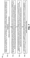
- Figure 7 is a flow diagram illustrating one implementation of a method 700 for search space sharing for cross-carrier scheduling by a base station 160.
- the base station 160 may generate 702, for the UE 102, information.
- the information may be included in the MIB (or SIB) which is broadcasted by the base station 160. Additionally or alternatively, the information may be one or more RRC parameters included in a RRC message.
- the base station 160 may transmit 702, to the UE 102, the generated information.
- the information generated on 702 may configure the UE 102 a plurality of serving cells for operation of carrier aggregation.
- the information generated on 702 may further configure the UE 102 for cross-carrier scheduling and configure carrier indicator field (CIF) value for respective configured carrier.
- the information generated on 702 may also provide the UE 102 CORESET configuration and search space configuration for a scheduling cell.
- the information generated on 702 may also provide the UE 102 search space configuration for a scheduled cell.
- the information generated on 702 may not provide the UE 102 CORESET configuration for a scheduled cell.
- the base station 160 may, based on the information transmitted on 702, transmit PDCCH candidates associated with one or more serving cells on the active DL BWP of the scheduling cell.
- the base station 160 may 704, based on the information transmitted on 702, transmit, to the UE 102, a PDCCH candidate with a CCE aggregation level (AL) in a first set of CCEs in a CORESET for a first DCI format associated with a first serving cell wherein the first set of CCEs is given at least based on the CIF value of the first serving cell and the first DCI format having a first size is used for the scheduling of PUSCH.
- the first DCI format used for the scheduling of PUSCH includes the first DCI format scheduling PUSCH transmission and/or the first DCI format releasing PUSCH transmission.
- the base station 160 may 706, based on the information transmitted on 702, transmit, to the UE 102, a PDCCH candidate with the CCE aggregation level (AL) in a second set of CCEs in the CORESET for a second DCI format associated with a second serving cell wherein the second set of CCEs is given at least based on the CIF value of the second serving cell and the second DCI format has a second size.
- the second DCI format is used for the scheduling of PUSCH.
- the second DCI format used for the scheduling of PUSCH includes the second DCI format scheduling PUSCH transmission and/or the second DCI format releasing PUSCH transmission.
- the base station 160 may receive, from the UE 102, a capability to indicate support of search space sharing for operation of carrier aggregation so that the UE 102 can receive a PDCCH through a PDCCH candidate for the second DCI format in the first set of CCEs in a case that the first size and the second size are same. If the base station 160 received the capability from the UE 102, the base station 160 may transmit a PDCCH through a PDCCH candidate for the second DCI format in the first set of CCEs in a case that the first size and the second size are same.
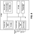
- FIG 8 illustrates various components that may be utilized in a UE 802.
- the UE 802 described in connection with Figure 8 may be implemented in accordance with the UE 102 described in connection with Figure 1 .
- the UE 802 includes a processor 881 that controls operation of the UE 802.
- the processor 881 may also be referred to as a central processing unit (CPU).
- Memory 887 which may include read-only memory (ROM), random access memory (RAM), a combination of the two or any type of device that may store information, provides instructions 883a and data 885a to the processor 881.
- a portion of the memory 887 may also include non-volatile random access memory (NVRAM).
- Instructions 883b and data 885b may also reside in the processor 881.
- Instructions 883b and/or data 885b loaded into the processor 881 may also include instructions 883a and/or data 885a from memory 887 that were loaded for execution or processing by the processor 881.
- the instructions 883b may be executed by the processor 881 to implement one or more of the methods 200 described above.
- the UE 802 may also include a housing that contains one or more transmitters 858 and one or more receivers 820 to allow transmission and reception of data.
- the transmitter(s) 858 and receiver(s) 820 may be combined into one or more transceivers 818.
- One or more antennas 822a-n are attached to the housing and electrically coupled to the transceiver 818.
- the various components of the UE 802 are coupled together by a bus system 889, which may include a power bus, a control signal bus and a status signal bus, in addition to a data bus. However, for the sake of clarity, the various buses are illustrated in Figure 8 as the bus system 889.
- the UE 802 may also include a digital signal processor (DSP) 891 for use in processing signals.
- DSP digital signal processor
- the UE 802 may also include a communications interface 893 that provides user access to the functions of the UE 802.
- the UE 802 illustrated in Figure 8 is a functional block diagram rather than a listing of specific components.
- Figure 9 illustrates various components that may be utilized in a base station 960.
- the base station 960 described in connection with Figure 9 may be implemented in accordance with the base station 160 described in connection with Figure 1 .
- the base station 960 includes a processor 981 that controls operation of the base station 960.
- the processor 981 may also be referred to as a central processing unit (CPU).
- Memory 987 which may include read-only memory (ROM), random access memory (RAM), a combination of the two or any type of device that may store information, provides instructions 983a and data 985a to the processor 981.
- a portion of the memory 987 may also include non-volatile random access memory (NVRAM).
- Instructions 983b and data 985b may also reside in the processor 981.
- Instructions 983b and/or data 985b loaded into the processor 981 may also include instructions 983a and/or data 985a from memory 987 that were loaded for execution or processing by the processor 981.
- the instructions 983b may be executed by the processor 981 to implement one or more of the methods 300 described above.
- the base station 960 may also include a housing that contains one or more transmitters 917 and one or more receivers 978 to allow transmission and reception of data.
- the transmitter(s) 917 and receiver(s) 978 may be combined into one or more transceivers 976.
- One or more antennas 980a-n are attached to the housing and electrically coupled to the transceiver 976.
- the various components of the base station 960 are coupled together by a bus system 989, which may include a power bus, a control signal bus and a status signal bus, in addition to a data bus. However, for the sake of clarity, the various buses are illustrated in Figure 9 as the bus system 989.
- the base station 960 may also include a digital signal processor (DSP) 991 for use in processing signals.
- the base station 960 may also include a communications interface 993 that provides user access to the functions of the base station 960.
- the base station 960 illustrated in Figure 9 is a functional block diagram rather than a listing of specific components.
- Computer-readable medium refers to any available medium that can be accessed by a computer or a processor.
- the term "computer-readable medium,” as used herein, may denote a computer- and/or processor-readable medium that is non-transitory and tangible.
- a computer-readable or processor-readable medium may comprise RAM, ROM, EEPROM, CD-ROM or other optical disk storage, magnetic disk storage or other magnetic storage devices, or any other medium that can be used to carry or store desired program code in the form of instructions or data structures and that can be accessed by a computer or processor.
- Disk and disc includes compact disc (CD), laser disc, optical disc, digital versatile disc (DVD), floppy disk and Blu-ray ® disc where disks usually reproduce data magnetically, while discs reproduce data optically with lasers.
- one or more of the methods described herein may be implemented in and/or performed using hardware.
- one or more of the methods described herein may be implemented in and/or realized using circuitry, a chipset, an application-specific integrated circuit (ASIC), a large-scale integrated circuit (LSI) or integrated circuit, etc.
- ASIC application-specific integrated circuit
- LSI large-scale integrated circuit
- Each of the methods disclosed herein comprises one or more steps or actions for achieving the described method.
- the method steps and/or actions may be interchanged with one another and/or combined into a single step without departing from the scope of the claims.
- the order and/or use of specific steps and/or actions may be modified without departing from the scope of the claims.
Landscapes
- Engineering & Computer Science (AREA)
- Signal Processing (AREA)
- Computer Networks & Wireless Communication (AREA)
- Mobile Radio Communication Systems (AREA)
Claims (3)
- Nutzerendgerät, UE (102), aufweisend:einen Empfänger (120), der so konfiguriert ist, dass ervon einer Basisstation (160) Informationen empfängt, um eine erste Dienstzelle und eine zweite Dienstzelle für eine trägerübergreifende Planung zu konfigurieren, und die Informationen, die einen ersten Trägerindikatorfeld-, CIF-, Wert für die erste Dienstzelle und einen zweiten CIF-Wert für die zweite Dienstzelle angeben, undein Operationsmodul (124), das so konfiguriert ist, dass es einen ersten Satz von Kandidaten eines physikalischen Downlink-Steuerkanals, PDCCH, mit einem Aggregationsniveau, AL, eines Steuerkanalelements, CCE, in einem ersten Satz von CCEs in einem Steuerungsressourcensatz, CORESET, für ein erstes Format einer Downlink-Steuerungsinformation, DCI, überwacht, das mit der ersten Dienstzelle assoziiert ist, wobei der erste Satz von CCEs zumindest basierend auf dem ersten CIF-Wert der ersten Dienstzelle gegeben ist und das erste DCI-Format eine erste Größe hat und für die Planung eines PUSCH verwendet wird, und einen PDCCH im ersten Satz von PDCCH-Kandidaten empfängt,und so konfiguriert ist, dass es einen zweiten Satz von PDCCH-Kandidaten mit dem CCE-AL in einem zweiten Satz von CCEs im CORESET für ein zweites DCI-Format überwacht, das mit der zweiten Dienstzelle assoziiert ist, wobei der zweite Satz von CCEs zumindest basierend auf dem zweiten CIF-Wert der zweiten Dienstzelle gegeben ist und das zweite DCI-Format eine zweite Größe hat und für einen gemeinsam genutzten physikalischen Uplink-Kanal, PUSCH, für eine Uplink-Genehmigung vom Typ 2 verwendet wird, einen PDCCH im zweiten Satz von PDCCH-Kandidaten freigibt und empfängt, wobeiin einem Fall, in dem die erste Größe und die zweite Größe gleich sind, das Operationsmodul ferner so konfiguriert ist, dass es über einen PDCCH-Kandidaten einen PDCCH für das zweite DCI-Format im ersten Satz von CCEs überwacht und empfängt.
- Basisstation (160), aufweisend:einen Sender (117), der so konfiguriert ist, dass erzu einem Nutzerendgerät, UE (102), Informationen sendet, um eine erste Dienstzelle und eine zweite Dienstzelle für eine trägerübergreifende Planung zu konfigurieren, und die Informationen, die einen ersten Trägerindikatorfeld-, CIF-, Wert für die erste Dienstzelle und einen zweiten CIF-Wert für die zweite Dienstzelle angeben, undeinen PDCCH über einen ersten Kandidaten eines physikalischen Downlink-Steuerkanals, PDCCH, mit einem Aggregationsniveau, AL, eines Steuerkanalelements, CCE, in einem ersten Satz von CCEs in einem Steuerungsressourcensatz, CORESET, für ein erstes Format einer Downlink-Steuerungsinformation, DCI, sendet, das mit der ersten Dienstzelle assoziiert ist, wobei der erste Satz von CCEs zumindest basierend auf dem ersten CIF-Wert der ersten Dienstzelle gegeben ist und das erste DCI-Format eine erste Größe hat und für die Planung eines PUSCH verwendet wird,einen PDCCH über einen zweiten PDCCH-Kandidaten mit dem CCE-AL in einem zweiten Satz von CCEs im CORESET für ein zweites DCI-Format sendet, das mit der zweiten Dienstzelle assoziiert ist, wobei der zweite Satz von CCEs zumindest basierend auf dem zweiten CIF-Wert der zweiten Dienstzelle gegeben ist und das zweite DCI-Format eine zweite Größe hat und für einen gemeinsam genutzten physikalischen Uplink-Kanal, PUSCH, für eine Uplink-Genehmigung vom Typ 2 verwendet wird, wobeiin einem Fall, in dem die erste Größe und die zweite Größe gleich sind, die Sendeeinheit ferner so konfiguriert ist, dass sie über einen PDCCH-Kandidaten einen PDCCH für das zweite DCI-Format im ersten Satz von CCEs sendet.
- Verfahren mittels eines Nutzerendgeräts, UE (102), aufweisend:Empfangen, von einer Basisstation (160), von Informationen, um eine erste Dienstzelle und eine zweite Dienstzelle für eine trägerübergreifende Planung zu konfigurieren, und die Informationen, die einen ersten Trägerindikatorfeld-, CIF-, Wert für die erste Dienstzelle und einen zweiten CIF-Wert für die zweite Dienstzelle angeben, undÜberwachen eines ersten Satzes von Kandidaten eines physikalischen Downlink-Steuerkanals, PDCCH, mit einem Aggregationsniveau, AL, eines Steuerkanalelements, CCE, in einem ersten Satz von CCEs in einem Steuerungsressourcensatz, CORESET, für ein erstes Format einer Downlink-Steuerungsinformation, DCI, das mit der ersten Dienstzelle assoziiert ist, wobei der erste Satz von CCEs zumindest basierend auf dem ersten CIF-Wert der erste Dienstzelle gegeben ist und das erste DCI-Format eine erste Größe hat und für die Planung eines PUSCH verwendet wird, und Empfangen eines PDCCH im ersten Satz von PDCCH-Kandidaten,Überwachen eines zweiten Satzes von PDCCH-Kandidaten mit dem CCE-AL in einem zweiten Satz von CCEs im CORESET für ein zweites DCI-Format, das mit der zweiten Dienstzelle assoziiert ist, wobei der zweite Satz von CCEs zumindest basierend auf dem zweiten CIF-Wert der zweiten Dienstzelle gegeben ist und das zweite DCI-Format eine zweite Größe hat und für einen gemeinsam genutzten physikalischen Uplink-Kanal, PUSCH, für eine Uplink-Genehmigung vom Typ 2 verwendet wird, Freigeben und Empfangen eines PDCCH im zweiten Satz von PDCCH-Kandidaten,in einem Fall, in dem die erste Größe und die zweite Größe gleich sind, Überwachen und Empfangen, über einen PDCCH-Kandidaten, eines PDCCH für das zweite DCI-Format im ersten Satz von CCEs.
Applications Claiming Priority (2)
| Application Number | Priority Date | Filing Date | Title |
|---|---|---|---|
| JP2020066615 | 2020-04-02 | ||
| PCT/JP2021/014836 WO2021201299A1 (en) | 2020-04-02 | 2021-04-01 | Terminal apparatus, base station apparatus, and communication method |
Publications (3)
| Publication Number | Publication Date |
|---|---|
| EP4128953A1 EP4128953A1 (de) | 2023-02-08 |
| EP4128953A4 EP4128953A4 (de) | 2024-04-03 |
| EP4128953B1 true EP4128953B1 (de) | 2025-07-02 |
Family
ID=77929607
Family Applications (1)
| Application Number | Title | Priority Date | Filing Date |
|---|---|---|---|
| EP21780709.8A Active EP4128953B1 (de) | 2020-04-02 | 2021-04-01 | Endgerätevorrichtung, basisstationsvorrichtung und kommunikationsverfahren |
Country Status (4)
| Country | Link |
|---|---|
| US (1) | US12495419B2 (de) |
| EP (1) | EP4128953B1 (de) |
| CN (1) | CN115380599B (de) |
| WO (1) | WO2021201299A1 (de) |
Families Citing this family (13)
| Publication number | Priority date | Publication date | Assignee | Title |
|---|---|---|---|---|
| US12034655B2 (en) * | 2019-07-06 | 2024-07-09 | Qualcomm Incorporated | DCI based xCarrier repetition and beam sweep |
| KR102937590B1 (ko) | 2020-08-06 | 2026-03-11 | 애플 인크. | 상이한 서브캐리어 간격 능력 보고를 갖는 크로스 캐리어 스케줄링 |
| CN115039488B (zh) * | 2020-08-07 | 2025-05-27 | 中兴通讯股份有限公司 | 用于通过单个下行控制信息调度多个小区的方法和设备 |
| KR20220113025A (ko) * | 2021-02-05 | 2022-08-12 | 삼성전자주식회사 | 무선 통신 시스템에서 스케줄링을 수행하기 위한 방법 및 장치 |
| US12446022B2 (en) * | 2021-03-19 | 2025-10-14 | Qualcomm Incorporated | Techniques for search space sharing for control channel repetition |
| US12267847B2 (en) * | 2021-06-04 | 2025-04-01 | Qualcomm Incorporated | Search space sharing for cross-carrier scheduling |
| EP4429149A4 (de) * | 2021-11-03 | 2025-08-20 | Beijing Xiaomi Mobile Software Co Ltd | Ressourcenbestimmungsverfahren und -vorrichtung, vorrichtung und speichermedium |
| CN116996182A (zh) * | 2022-04-24 | 2023-11-03 | 上海朗帛通信技术有限公司 | 一种用于无线通信的节点中的方法和装置 |
| US12414126B2 (en) * | 2022-08-08 | 2025-09-09 | Qualcomm Incorporated | Scheduled cell identification for multi-cell scheduling |
| CN117676854A (zh) * | 2022-08-10 | 2024-03-08 | 北京三星通信技术研究有限公司 | 由用户设备执行的方法、由基站执行的方法及对应的设备 |
| CN117998628A (zh) * | 2022-11-03 | 2024-05-07 | 上海朗帛通信技术有限公司 | 一种用于无线通信的节点中的方法和装置 |
| CN120584535A (zh) * | 2023-02-17 | 2025-09-02 | 中兴通讯股份有限公司 | 用于调度机制的方法、设备和系统 |
| US20250150226A1 (en) * | 2023-11-03 | 2025-05-08 | Qualcomm Incorporated | Search space set configuration for a pair of downlink and uplink cells |
Family Cites Families (8)
| Publication number | Priority date | Publication date | Assignee | Title |
|---|---|---|---|---|
| WO2010131925A2 (ko) | 2009-05-14 | 2010-11-18 | 엘지전자 주식회사 | 다중 반송파 시스템에서 제어채널을 모니터링하는 장치 및 방법 |
| EP2639989A1 (de) * | 2012-03-16 | 2013-09-18 | Panasonic Corporation | Suchraum für ePDCCH-Steuerungsinformationen in einem OFDM-basierten mobilen Kommunikationssystem |
| KR102247049B1 (ko) * | 2016-08-30 | 2021-04-30 | 엘지전자 주식회사 | 무선 통신 시스템에서 하향링크 제어 정보 전송 방법 및 상기 방법을 이용하는 장치 |
| JP6840239B2 (ja) * | 2016-11-04 | 2021-03-10 | エルジー エレクトロニクス インコーポレイティド | 無線通信システムにおいてデータを送受信する方法及びそのための装置 |
| US11212786B2 (en) * | 2018-05-09 | 2021-12-28 | Qualcomm Incorporated | Service and format indication techniques for downlink control information |
| ES2971507T3 (es) | 2018-07-27 | 2024-06-05 | Asustek Comp Inc | Procedimiento y aparato para el procedimiento de ahorro de energía en la recepción PDSCH (canal físico compartido de enlace descendente) en un sistema de comunicación inalámbrica. |
| US11558873B2 (en) * | 2019-11-22 | 2023-01-17 | Samsung Electronics Co., Ltd. | Method and apparatus for group scheduling for PDCCH overhead reduction |
| WO2021151223A1 (en) * | 2020-01-29 | 2021-08-05 | Qualcomm Incorporated | Cross-carrier scheduling techniques for wireless communications systems |
-
2021
- 2021-04-01 EP EP21780709.8A patent/EP4128953B1/de active Active
- 2021-04-01 WO PCT/JP2021/014836 patent/WO2021201299A1/en not_active Ceased
- 2021-04-01 US US17/915,083 patent/US12495419B2/en active Active
- 2021-04-01 CN CN202180025318.3A patent/CN115380599B/zh active Active
Also Published As
| Publication number | Publication date |
|---|---|
| US20230156700A1 (en) | 2023-05-18 |
| EP4128953A1 (de) | 2023-02-08 |
| CN115380599B (zh) | 2026-04-28 |
| CN115380599A (zh) | 2022-11-22 |
| US12495419B2 (en) | 2025-12-09 |
| EP4128953A4 (de) | 2024-04-03 |
| WO2021201299A1 (en) | 2021-10-07 |
Similar Documents
| Publication | Publication Date | Title |
|---|---|---|
| EP4128953B1 (de) | Endgerätevorrichtung, basisstationsvorrichtung und kommunikationsverfahren | |
| US12520300B2 (en) | Terminal apparatus, base station apparatus, and communication method | |
| US12143844B2 (en) | User equipment, base station, and method | |
| US11799589B2 (en) | Terminal apparatus, base station apparatus, and communication method | |
| US12114339B2 (en) | User equipment, base station, and method | |
| US12289257B2 (en) | Terminal apparatus, base station apparatus, and communication method | |
| US12381692B2 (en) | Terminal apparatus, base station apparatus, and communication method | |
| US12389375B2 (en) | Terminal apparatus, base station apparatus, and communication method | |
| US12581483B2 (en) | Terminal apparatus, base station apparatus, and communication method for flexible physical downlink control channel (PDCCH) repetitions | |
| US20220345921A1 (en) | Terminal apparatus, base station apparatus, and communication method | |
| US20220264341A1 (en) | User equipment, base station apparatus, and method | |
| US20230292316A1 (en) | User equipments, base stations, and methods | |
| US20230179386A1 (en) | Terminal apparatus, base station apparatus, and communication method | |
| US20230413288A1 (en) | User equipment, base station, and communication method | |
| US12199910B2 (en) | Terminal apparatus, base station apparatus, and communication method | |
| US12513768B2 (en) | User equipments, base stations, and methods | |
| US20240023185A1 (en) | User equipments, base stations, and methods | |
| WO2022196789A1 (en) | User equipments, base stations, and methods | |
| WO2023054654A1 (en) | User equipments, base stations, and communication methods | |
| WO2022080499A1 (en) | User equipments, base stations, and methods |
Legal Events
| Date | Code | Title | Description |
|---|---|---|---|
| STAA | Information on the status of an ep patent application or granted ep patent |
Free format text: STATUS: THE INTERNATIONAL PUBLICATION HAS BEEN MADE |
|
| PUAI | Public reference made under article 153(3) epc to a published international application that has entered the european phase |
Free format text: ORIGINAL CODE: 0009012 |
|
| STAA | Information on the status of an ep patent application or granted ep patent |
Free format text: STATUS: REQUEST FOR EXAMINATION WAS MADE |
|
| 17P | Request for examination filed |
Effective date: 20220929 |
|
| AK | Designated contracting states |
Kind code of ref document: A1 Designated state(s): AL AT BE BG CH CY CZ DE DK EE ES FI FR GB GR HR HU IE IS IT LI LT LU LV MC MK MT NL NO PL PT RO RS SE SI SK SM TR |
|
| DAV | Request for validation of the european patent (deleted) | ||
| DAX | Request for extension of the european patent (deleted) | ||
| REG | Reference to a national code |
Ref legal event code: R079 Ref country code: DE Ref document number: 602021033442 Country of ref document: DE Free format text: PREVIOUS MAIN CLASS: H04W0072040000 Ipc: H04L0005000000 |
|
| A4 | Supplementary search report drawn up and despatched |
Effective date: 20240306 |
|
| RIC1 | Information provided on ipc code assigned before grant |
Ipc: H04W 72/23 20230101ALI20240229BHEP Ipc: H04L 5/00 20060101AFI20240229BHEP |
|
| GRAP | Despatch of communication of intention to grant a patent |
Free format text: ORIGINAL CODE: EPIDOSNIGR1 |
|
| STAA | Information on the status of an ep patent application or granted ep patent |
Free format text: STATUS: GRANT OF PATENT IS INTENDED |
|
| RIC1 | Information provided on ipc code assigned before grant |
Ipc: H04W 72/23 20230101ALI20250212BHEP Ipc: H04L 5/00 20060101AFI20250212BHEP |
|
| INTG | Intention to grant announced |
Effective date: 20250225 |
|
| GRAS | Grant fee paid |
Free format text: ORIGINAL CODE: EPIDOSNIGR3 |
|
| GRAA | (expected) grant |
Free format text: ORIGINAL CODE: 0009210 |
|
| STAA | Information on the status of an ep patent application or granted ep patent |
Free format text: STATUS: THE PATENT HAS BEEN GRANTED |
|
| AK | Designated contracting states |
Kind code of ref document: B1 Designated state(s): AL AT BE BG CH CY CZ DE DK EE ES FI FR GB GR HR HU IE IS IT LI LT LU LV MC MK MT NL NO PL PT RO RS SE SI SK SM TR |
|
| REG | Reference to a national code |
Ref country code: GB Ref legal event code: FG4D |
|
| REG | Reference to a national code |
Ref country code: CH Ref legal event code: EP |
|
| REG | Reference to a national code |
Ref country code: DE Ref legal event code: R096 Ref document number: 602021033442 Country of ref document: DE |
|
| REG | Reference to a national code |
Ref country code: IE Ref legal event code: FG4D |
|
| REG | Reference to a national code |
Ref country code: NL Ref legal event code: MP Effective date: 20250702 |
|
| PG25 | Lapsed in a contracting state [announced via postgrant information from national office to epo] |
Ref country code: PT Free format text: LAPSE BECAUSE OF FAILURE TO SUBMIT A TRANSLATION OF THE DESCRIPTION OR TO PAY THE FEE WITHIN THE PRESCRIBED TIME-LIMIT Effective date: 20251103 |
|
| PG25 | Lapsed in a contracting state [announced via postgrant information from national office to epo] |
Ref country code: NL Free format text: LAPSE BECAUSE OF FAILURE TO SUBMIT A TRANSLATION OF THE DESCRIPTION OR TO PAY THE FEE WITHIN THE PRESCRIBED TIME-LIMIT Effective date: 20250702 |
|
| REG | Reference to a national code |
Ref country code: AT Ref legal event code: MK05 Ref document number: 1810531 Country of ref document: AT Kind code of ref document: T Effective date: 20250702 |
|
| PG25 | Lapsed in a contracting state [announced via postgrant information from national office to epo] |
Ref country code: IS Free format text: LAPSE BECAUSE OF FAILURE TO SUBMIT A TRANSLATION OF THE DESCRIPTION OR TO PAY THE FEE WITHIN THE PRESCRIBED TIME-LIMIT Effective date: 20251102 |
|
| PG25 | Lapsed in a contracting state [announced via postgrant information from national office to epo] |
Ref country code: NO Free format text: LAPSE BECAUSE OF FAILURE TO SUBMIT A TRANSLATION OF THE DESCRIPTION OR TO PAY THE FEE WITHIN THE PRESCRIBED TIME-LIMIT Effective date: 20251002 |
|
| REG | Reference to a national code |
Ref country code: LT Ref legal event code: MG9D |
|
| PG25 | Lapsed in a contracting state [announced via postgrant information from national office to epo] |
Ref country code: AT Free format text: LAPSE BECAUSE OF FAILURE TO SUBMIT A TRANSLATION OF THE DESCRIPTION OR TO PAY THE FEE WITHIN THE PRESCRIBED TIME-LIMIT Effective date: 20250702 |
|
| PG25 | Lapsed in a contracting state [announced via postgrant information from national office to epo] |
Ref country code: FI Free format text: LAPSE BECAUSE OF FAILURE TO SUBMIT A TRANSLATION OF THE DESCRIPTION OR TO PAY THE FEE WITHIN THE PRESCRIBED TIME-LIMIT Effective date: 20250702 |
|
| PG25 | Lapsed in a contracting state [announced via postgrant information from national office to epo] |
Ref country code: HR Free format text: LAPSE BECAUSE OF FAILURE TO SUBMIT A TRANSLATION OF THE DESCRIPTION OR TO PAY THE FEE WITHIN THE PRESCRIBED TIME-LIMIT Effective date: 20250702 |
|
| PG25 | Lapsed in a contracting state [announced via postgrant information from national office to epo] |
Ref country code: GR Free format text: LAPSE BECAUSE OF FAILURE TO SUBMIT A TRANSLATION OF THE DESCRIPTION OR TO PAY THE FEE WITHIN THE PRESCRIBED TIME-LIMIT Effective date: 20251003 |
|
| PG25 | Lapsed in a contracting state [announced via postgrant information from national office to epo] |
Ref country code: SE Free format text: LAPSE BECAUSE OF FAILURE TO SUBMIT A TRANSLATION OF THE DESCRIPTION OR TO PAY THE FEE WITHIN THE PRESCRIBED TIME-LIMIT Effective date: 20250702 Ref country code: CZ Free format text: LAPSE BECAUSE OF FAILURE TO SUBMIT A TRANSLATION OF THE DESCRIPTION OR TO PAY THE FEE WITHIN THE PRESCRIBED TIME-LIMIT Effective date: 20250702 |
|
| PG25 | Lapsed in a contracting state [announced via postgrant information from national office to epo] |
Ref country code: LV Free format text: LAPSE BECAUSE OF FAILURE TO SUBMIT A TRANSLATION OF THE DESCRIPTION OR TO PAY THE FEE WITHIN THE PRESCRIBED TIME-LIMIT Effective date: 20250702 |
|
| PG25 | Lapsed in a contracting state [announced via postgrant information from national office to epo] |
Ref country code: BG Free format text: LAPSE BECAUSE OF FAILURE TO SUBMIT A TRANSLATION OF THE DESCRIPTION OR TO PAY THE FEE WITHIN THE PRESCRIBED TIME-LIMIT Effective date: 20250702 Ref country code: PL Free format text: LAPSE BECAUSE OF FAILURE TO SUBMIT A TRANSLATION OF THE DESCRIPTION OR TO PAY THE FEE WITHIN THE PRESCRIBED TIME-LIMIT Effective date: 20250702 |
|
| PG25 | Lapsed in a contracting state [announced via postgrant information from national office to epo] |
Ref country code: RS Free format text: LAPSE BECAUSE OF FAILURE TO SUBMIT A TRANSLATION OF THE DESCRIPTION OR TO PAY THE FEE WITHIN THE PRESCRIBED TIME-LIMIT Effective date: 20251002 |
|
| PG25 | Lapsed in a contracting state [announced via postgrant information from national office to epo] |
Ref country code: ES Free format text: LAPSE BECAUSE OF FAILURE TO SUBMIT A TRANSLATION OF THE DESCRIPTION OR TO PAY THE FEE WITHIN THE PRESCRIBED TIME-LIMIT Effective date: 20250702 |
|
| PG25 | Lapsed in a contracting state [announced via postgrant information from national office to epo] |
Ref country code: SM Free format text: LAPSE BECAUSE OF FAILURE TO SUBMIT A TRANSLATION OF THE DESCRIPTION OR TO PAY THE FEE WITHIN THE PRESCRIBED TIME-LIMIT Effective date: 20250702 |
|
| PGFP | Annual fee paid to national office [announced via postgrant information from national office to epo] |
Ref country code: GB Payment date: 20260306 Year of fee payment: 6 |
|
| PG25 | Lapsed in a contracting state [announced via postgrant information from national office to epo] |
Ref country code: DK Free format text: LAPSE BECAUSE OF FAILURE TO SUBMIT A TRANSLATION OF THE DESCRIPTION OR TO PAY THE FEE WITHIN THE PRESCRIBED TIME-LIMIT Effective date: 20250702 |
|
| PG25 | Lapsed in a contracting state [announced via postgrant information from national office to epo] |
Ref country code: IT Free format text: LAPSE BECAUSE OF FAILURE TO SUBMIT A TRANSLATION OF THE DESCRIPTION OR TO PAY THE FEE WITHIN THE PRESCRIBED TIME-LIMIT Effective date: 20250702 |
|
| PG25 | Lapsed in a contracting state [announced via postgrant information from national office to epo] |
Ref country code: EE Free format text: LAPSE BECAUSE OF FAILURE TO SUBMIT A TRANSLATION OF THE DESCRIPTION OR TO PAY THE FEE WITHIN THE PRESCRIBED TIME-LIMIT Effective date: 20250702 Ref country code: SK Free format text: LAPSE BECAUSE OF FAILURE TO SUBMIT A TRANSLATION OF THE DESCRIPTION OR TO PAY THE FEE WITHIN THE PRESCRIBED TIME-LIMIT Effective date: 20250702 |