EP4129111B1 - Bouton pression pour vêtements - Google Patents
Bouton pression pour vêtements Download PDFInfo
- Publication number
- EP4129111B1 EP4129111B1 EP22188604.7A EP22188604A EP4129111B1 EP 4129111 B1 EP4129111 B1 EP 4129111B1 EP 22188604 A EP22188604 A EP 22188604A EP 4129111 B1 EP4129111 B1 EP 4129111B1
- Authority
- EP
- European Patent Office
- Prior art keywords
- snap button
- elastically yielding
- female body
- development
- respect
- Prior art date
- Legal status (The legal status is an assumption and is not a legal conclusion. Google has not performed a legal analysis and makes no representation as to the accuracy of the status listed.)
- Active
Links
Images

Classifications
-
- A—HUMAN NECESSITIES
- A44—HABERDASHERY; JEWELLERY
- A44B—BUTTONS, PINS, BUCKLES, SLIDE FASTENERS, OR THE LIKE
- A44B17/00—Press-button or snap fasteners
- A44B17/0011—Press-button fasteners in which the elastic retaining action is obtained by a spring working in the plane of the fastener
Definitions
- the present invention relates to a snap button for garments/clothing, in particular for fastening and / or buttoning of clothing. More in detail, the present invention refers to a snap button, also known by the term automatic button for mechanically connecting two flaps, normally of a suit, for example a sports suit.
- the present invention finds advantageous use in the technical sector of the production and marketing of small parts, in particular metal, and of devices and accessories in the clothing sector, and more generally in the technical sector of the production and marketing of clothes, and clothing.
- buttons are known in the technical sector of reference, and in particular the snap buttons are known, also known in technical jargon as automatic buttons.
- These snap buttons are devices capable of mechanically joining two free flaps of a suit, normally of sportswear, such as for example two front flaps of a jacket, for example of a gym suit.
- the snap button of the known type comprises a female body, intended to be mechanically fixed to a first free edge of the aforementioned suit, and a male body, intended to be mechanically fixed to a second free edge of the dress, to be joined with the first flap for buttoning and closing said dress or garment.
- the male body of the known type snap button is configured to be mechanically coupled in a removable manner with the female body of the button itself, in order to mechanically connect the respective flaps of the garment to join them together.
- the female body defines a housing seat configured to receive a protruding element of the male body and lock the latter in a removable manner.
- the female body comprises an elastically yielding element that is movable during the insertion of the protruding element into the housing seat to assume a locking configuration, in which the elastically yielding element blocks the protruding element in the housing seat itself.
- the elastically yielding element of the female body of the snap button of the known type comprises an elastically yielding annular element, such as for example an elastic washer, i.e.
- the elastically yielding annular element is movable between a retracted configuration, in which it defines a first internal diameter, and an expanded configuration, in which it defines a second internal diameter in May of the first internal diameter.
- the elastically yielding annular element is equipped with an internal diameter less than or equal to the overall dimensions of the protruding element of the male body, and configured to be intercepted by the latter during the insertion of the protruding element itself, to expand elastically the annular body, from the retracted configuration to the dilated configuration, to then return elastically to the retracted configuration when the protruding element is completely inserted in the housing seat.
- the retracted configuration coincides with the locking configuration when the protruding element of the male body is completely inserted inside the housing seat of the female body.
- the elastically yielding annular element is arranged around an access mouth of the housing seat, held inside a special annular groove.
- the annular groove located at the access mouth of the housing seat normally has larger internal dimensions than those of the elastically yielding element, in order to allow the latter to expand between the retracted configuration and the dilated configuration.
- the main drawback lies in the fact that the elastically yielding element housed in the annular groove defines a mechanical play with the internal walls of the latter. This mechanical play results in the fact that, with the snap button open, or with the flaps of the garment separated, the elastically yielding element hits the walls of the annular groove, generating an annoying rattle.
- the jingle generated by the known type of snap button is unpleasant for the user and in fact makes this type of button unusable in fine clothing, relegating its usability to sportswear only, for which the tolerance to such noises is generally greater.
- the object of the present invention is to propose a snap button for garments which allows to obviate, at least in part, the drawbacks of the aforementioned prior art.
- a further purpose of the invention is to provide a snap button for clothing that is silent even when open, i.e. when the garment is held with the flaps separated from each other.
- a further purpose of the invention is to provide a snap button for clothing that is structurally completely reliable.
- a further purpose of the invention is to provide a snap button for clothing that is functionally completely reliable.
- a further purpose of the present invention is to provide a snap button for clothing which is simple and economical to make.
- a further purpose of the present invention is to provide a snap button for clothing which is economically advantageous.
- a further purpose of the present invention is to provide a snap button for garments which can be easily manufactured on an industrial level.
- a further purpose of the invention is to provide a snap button for garments that can be colored and / or customized.
- a further purpose of the invention is to provide a snap button for garments that is suitable for any type of garment.
- a further purpose of the present invention is to provide a snap button for garments which is an alternative and / or an improvement with respect to traditional solutions.
- Another purpose of the present invention is to propose a snap button for garments which has an alternative and / or improved configuration, both in terms of construction and in terms of function, with respect to traditional solutions.
- the snap button in question is advantageously used in the technical sector of the production and marketing of accessories for garments, and in particular in the technical sector of the production and marketing of small parts, in particular metal and / or in the technical sector of the production and marketing of clothes, and clothing.
- the snap button for garments object of the present invention is suitably applicable to substantially any type of garment, and in particular it is advantageously applicable to sports garments.
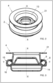
- the snap button 1 comprises at least one female body 2, extending along a direction of development X between a first face 2'and a second face 2", internally defining at least one housing seat 3 placed in communication with the external from an access mouth 20 obtained in correspondence with said first face 2'.
- the female body 2 is made of metallic material, such as for example brass, copper, stainless iron, bronze or alpaca. Otherwise, the female body 2 can be made of plastic material, such as in particular a casting material, for example zamak.
- the housing seat 3 extends along the direction of development X with substantially constant overall dimensions, defining a shape, for example, substantially cylindrical.
- the female body 2 comprises a bottom wall 12 at the second end 2" which defines the housing seat 3.
- the bottom wall 12 of the female body 2 is equipped with a through hole 13.
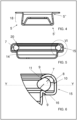
- the snap button according to the invention further comprises at least one male body 4 comprising at least one protruding element 5 which can be moved at least along said direction of development X at least between a closing position, in which it is at least partially housed inside said seat of housing 3 of said female body 2 through said access mouth 20 and an opening position, in which it is extracted from said housing seat 4.
- the female body 2 of the button 1 is intended to be mechanically bonded to a first flap of a garment (not illustrated in the attached figures) and the male body 4 is designed to be mechanically bonded to a second flap of the garment to be mechanically connected to the first flap by means of the button 1 according to the invention.
- the female body 2 comprises a side wall 14 which laterally delimits the housing seat 3 and is designed externally to be mechanically associated with the fabric of the aforementioned first flap of the garment.
- the female body 2 comprises elastic retaining means 6 arranged in correspondence with said access mouth 20 of said female body 2, configured to detachably retain said protruding element 5 in said closed position and comprising at least one elastically yielding element 7 housed in a groove 8 formed in correspondence with said access mouth 20 and configured to intercept said protruding element 5 of said male body 4 in its movement between said closed position and said open position.
- said female element 2 comprises at least one abutment wall 9 which delimits said groove 8 and abuts said elastically yielding element 7 to prevent the movements of said elastically yielding element along said direction of development X.
- the elastically yielding element 7 of the elastic retaining means 6 normally remains in abutment against the abutment wall 9, preventing it from moving parallel to the direction of development X and obviating the risk that, striking against the internal walls of the groove 8 , you generate unwanted noises.
- the snap button according to the invention allows to prevent the movements parallel to the development direction X of the elastically yielding element 7 but allows its expanding movement inside the groove 8 to allow its movement from the retracted configuration to that expanded.
- the groove 8 remains defined inside an annular shoulder 15 provided substantially at the first end 2'of the female body 2.
- the annular shoulder 15 in which the annular groove 8 remains defined protrudes radially with respect to the direction of development. X with respect to the side wall 14 of the female body 2.
- the annular shoulder 15 develops radially starting from the side wall 14 with a support crown 16 intended to be placed against the fabric of the flap on which the female body 2 of the snap button 1 according to the invention will be applied.
- the elastically yielding element 7 is movable between a retracted configuration, in which it abuts against said abutment wall 9 of said groove 8, and an enlarged configuration, in which said elastically yielding element 7 is pushed into said groove 8 by said protruding element 5 of said male body 4 radially with respect to said development direction X.
- the elastically yielding element 7 has an annular shape, is housed inside the groove 8, and is preferably made of metal material.
- the elastically yielding element 7 is equipped with a separation section 17, designed to define a continuity separation section of the annular development of the elastically yielding element 7 itself.
- This separation section 17 advantageously allows the widening of the elastically yielding element 7 in its movement between the retracted configuration and the enlarged configuration, inside the groove 8.
- said protruding element 5 of said male body 4 extends between a first free end 5', equipped with a first transverse dimension, and a second end 5'.
- said protruding element 5 is equipped with at least a narrow section 18 interposed between said first end 5'and said second end 5' with a smaller transverse dimension compared to said first dimension.
- the protruding body 5 has a substantially frusto-conical shape.
- the male body 4 comprises a shoulder 21 protruding radially from the second end 5" of the protruding element 5.
- the shoulder 21 preferably has a substantially annular shape and is configured to abut against an upper wall 22 of the female body 2, in correspondence of the first end 2'of the latter, with the male body in its closed position.
- the elastically yielding element 7 internally defines a passage opening for said protruding element 5, in which said passage opening extends, with said elastically yielding element 7 in retracted configuration, less than or equal to said first bulk of said first free end 5'of said protruding element 5.
- the protruding element 5 passes through the access mouth 20 and intercepts an internal portion of the elastically yielding element 7, protruding from the groove 8, and forces the movement of the elastically yielding element 7 from its narrow configuration to the enlarged one.
- the protruding element 5 occupies the housing seat 3 and the elastically yielding element 7 of the elastic holding means 6 slides along the protruding element 5 until it reaches the narrow section 18 of the latter, elastically returning from the enlarged configuration to the narrow configuration, elastically locking the protruding element 5 inside the housing seat 3 and therefore mechanically connecting in a removable manner the male body and the female body of the button according to the invention.
- said elastically yielding element 7 is mechanically locked around said protruding element 5 in correspondence with said narrow section 18 with said male body 4 in the closed position.
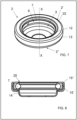
- said female body 2 comprises an annular bottom wall 10, which delimits said groove 8 and extends around the direction of development X.
- the female body 2 is conveniently provided with an annular opening 11 opposite said annular bottom wall 10 crossed by said elastically yielding element 7 in a retracted configuration.
- said abutment wall 9 delimits said annular gap 11 with an annular edge thereof.
- the abutment wall 9 is inclined and at least partially opposed to said bottom wall 10, delimiting said annular opening 11 with an annular edge thereof and receiving the abutment said elastically yielding element 7 in a retracted configuration.
- said at least one abutment wall 9 blocks the movements of said elastically yielding element 7 with respect to a transverse direction Y orthogonal with respect to said development direction X.
- the abutment wall 9 is at least one folded edge of the shoulder 15 of the female body 2.
- the female body 2 is made in a single body, for example by punching, in metallic material, and the shoulder 15 is made by bending of a single circular side flap.
- the annular opening 11 has an amplitude, parallel to the direction of development X, smaller than the size of the elastically yielding element 7, to block the latter in abutment against the abutment wall 9.
- the diameter of the circle that remains defined internally in the annular gap 11 is preferably greater than the diameter that remains defined internally to the elastically yielding element 7 in its retracted configuration.
- the elastically yielding element 7 protrudes for at least a portion of it from the annular opening 11, configured to be intercepted by the protruding element 5 of the male body 4.
- said female body 2 comprises two abutment walls 9, provided with two corresponding annular edges which define each other said annular gap 11.
- the female body 2 comprises a first abutment wall 9 which substantially defines the access mouth 20 to the housing seat 3 and an abutment wall 9 internal to the housing seat 3 itself.
- the two annular edges are parallel to each other and spaced parallel to the direction of development X.
- said elastically yielding element 7 has an oblong-shaped cross section, in which said section extends along a transverse direction Y orthogonal with respect to said development direction X.
- the internal extension of the groove 8 parallel to the transverse direction Y is greater than the extension of the cross section of the resiliently compliant element 7 parallel to the same transverse direction Y.
- the groove 8 allows the resiliently compliant element to expand from retracted configuration to expanded configuration.
- the cross section of the elastically yielding element is to be understood as made along a plane of section passing through the direction of development X of the female body 2.
- the cross section of the elastically yielding element 7 defines a restricted portion, which faces the abutment walls 9.
- the restricted portion of the cross section of the elastically yielding element 7 is equipped with at least one inclined wall and preferably two inclined walls.
- said cross section of said elastically yielding element 7 defines at least one inclined wall with respect to said transverse direction Y, configured to abut against said abutment wall 9 with said elastically yielding element 7 in retracted position.
- the cross section of the elastically yielding element 7 is equipped with two distinct inclined walls, which develop at an angle with respect to the transverse axis Y approaching each other towards the direction of development X.
- said cross section of said elastically yielding element 7 has a substantially drop shape, or has a substantially ogival shape, with a narrow portion facing the at least one abutment wall 9.
- the female body 2 of the snap button 1 defines, with the annular shoulder 15, a substantially flat upper annular wall 22, configured to receive the shoulder 21 of the male body 4 with the latter in the closed position.
- the annular shoulder 15 which internally defines the groove 8 for the elastically yielding element 7 is made of two half-shells, in which the first half-shell 15'is preferably made in a single body with the side wall 14, in particular by bending, and the second half-shell is applied to the first half-shell and mechanically bonded to the latter by means of fixing, for example by welding or by interlocking.
- the second half-shell can be made in any desired shape, not being subject to the limitation of forming by bending.
- the second half-shell can be made of a different material than the first half-shell and / or have a different and / or more expensive color than that of the first half-shell.
- the present invention also relates to a female body for a snap button of the type described up to now, of which all the numerical references will be kept for simplicity of explanation.
- the female body for a snap button for garments extends along a direction of development X between a first face 2'and a second face 2", internally defining at least one housing seat 3 placed in communication with the external from an access mouth 20 obtained in correspondence with said first face 2'.
- the female body 2 comprising elastic retaining means 6 arranged in correspondence with said access mouth 20, configured to detachably retain a protruding element 5 of a male body 4 of said snap button and comprising at least one elastically yielding element 7 housed in a groove 8 formed in correspondence with said access mouth 20 and configured to intercept said protruding element 5 of said male body 4 in its movement between a closed position and an open position.
- said female element comprises at least one abutment wall 9 which delimits said groove 8 and abuts said elastically yielding element 7 to prevent the movements of said elastically yielding element along said direction of development X.
- the female body in question also comprises an annular bottom wall 10, which delimits said groove (8) and extends around the direction of development X.
- the female body is also provided with an annular opening 11 opposite said annular bottom wall 10 crossed by said elastically yielding element 7 in a retracted configuration.
- the abutment wall 9 is suitably inclined and at least partially opposed to said bottom wall 10, delimiting said annular opening 11 with an annular edge thereof and receiving in abutment said elastically yielding element 7 in retracted configuration.
- said at least one abutment wall 9 blocks the movements of said elastically yielding element 7 with respect to a transverse direction Y orthogonal with respect to said development direction X.
- said female body 2 comprises two inclined abutment walls 9 substantially opposite and facing each other with respect to said bottom wall 10 to abut said elastically yielding element 7 in retracted configuration.
- the snap button for clothing is particularly advantageous in that:
Landscapes
- Slide Fasteners, Snap Fasteners, And Hook Fasteners (AREA)
Claims (14)
- Corps femelle pour un bouton pression pour vêtements, s'étendant selon une direction de développement (X) entre une première face (2') et une deuxième face (2"), définissant intérieurement au moins un siège de logement (3) mis en communication avec l'extérieur par une bouche d'accès (20) obtenue en correspondance avec ladite première face (2'); comprenant des moyens de maintien élastiques (6) disposés au niveau de ladite bouche d'accès (20), configurés pour retenir de manière amovible un élément en saillie (5) d'un corps mâle (4) dudit bouton pression; et comprenant au moins un élément élastiquement souple (7) logé dans une rainure (8) formée en correspondance avec ladite bouche d'accès (20) et configuré pour intercepter ledit élément en saillie (5) dudit corps mâle (4) dans son mouvement entre une position de fermeture et une position d'ouverture;- dans lequel ledit élément femelle comprend au moins une paroi de butée (9) qui délimite ladite rainure (8) et vient en butée contre ledit élément élastique souple (7) pour empêcher les mouvements dudit élément élastique souple le long de ladite direction de développement (X); caractérisé en ce que ledit corps femelle (2) comprend en outre :ladite paroi de butée (9) étant inclinée et au moins partiellement opposée à ladite paroi de fond (10), délimitant ladite ouverture annulaire (11) avec un bord annulaire de celle-ci et recevant en butée ledit élément élastique souple (7) en une configuration rétractée.- une paroi annulaire de fond (10), qui délimite ladite rainure (8), s'étendant autour de la direction de développement (X);- une ouverture annulaire (11) opposée à ladite paroi annulaire de fond (10) traversée par ledit élément élastique souple (7) en une configuration rétractée;
- Corps femelle pour un bouton pression pour vêtements selon la revendication 1, caractérisé en ce que ledit élément élastique souple (7) est mobile entre une configuration rétractée, dans laquelle il vient en butée contre ladite paroi de butée (9) de ladite rainure (8), et une configuration élargie, dans laquelle ledit élément élastique souple (7) est poussé dans ladite rainure (8) par ledit élément en saillie (5) dudit corps mâle (4) radialement par rapport à ladite direction de développement (X).
- Corps femelle d'un bouton pression selon l'une ou plusieurs des revendications précédentes, caractérisé en ce que ledit corps femelle (2) comprend deux parois de butée (9), pourvues de deux bords annulaires correspondants qui définissent entre eux ledit espace annulaire (11).
- Corps femelle d'un bouton pression selon la revendication 3, caractérisé en ce que ledit corps femelle (2) comprend deux parois de butée inclinées (9) sensiblement opposées et en regard l'une de l'autre par rapport à ladite paroi de fond (10) pour venir en butée contre ledit élément élastiquement souple (7) dans la configuration rétractée.
- Corps femelle d'un bouton pression selon la revendication 3 ou 4, caractérisé en ce que ledit élément élastique souple (7) présente une section transversale de forme oblongue, dans laquelle ladite section s'étend selon une direction transversale (Y) orthogonale par rapport à ladite direction de développement (X).
- Corps femelle d'un bouton pression selon la revendication 5, caractérisé en ce que ladite section transversale dudit élément élastique souple (7) définit au moins une paroi inclinée par rapport à ladite direction transversale (Y), configurée pour venir en butée contre ladite paroi de butée avec ledit élément élastique souple (7) dans la position rétractée.
- Corps femelle d'un bouton pression selon la revendication 5 ou 6, caractérisé en ce que ladite section transversale dudit élément élastique (7) présente une forme sensiblement en goutte, ou présente une forme sensiblement ogivale, avec une partie étroite faisant face à ladite au moins une paroi de butée (9).
- Corps femelle d'un bouton pression selon l'une ou plusieurs des revendications précédentes, caractérisé en ce que ladite au moins une paroi de butée (9) bloque les mouvements dudit élément élastiquement souple (7) par rapport à une direction transversale (Y) orthogonale par rapport à ladite direction de développement (X).
- Corps femelle d'un bouton pression selon l'une ou plusieurs des revendications précédentes, caractérisé en ce que ladite au moins une paroi de butée (9) bloque les mouvements dudit élément élastiquement souple (7) par rapport à une direction transversale (Y) orthogonale par rapport à ladite direction de développement (X).
- Corps femelle d'un bouton pression selon l'une ou plusieurs des revendications précédentes, caractérisé en ce qu'il comprend deux parois de butée inclinées (9) sensiblement opposées et en regard l'une de l'autre par rapport à ladite paroi de fond (10) pour recevoir en butée ledit élément élastique souple (7) dans une configuration rétractée.
- Bouton pression pour vêtements, comprenant:- au moins un corps femelle (2) selon l'une des revendications précédentes;- au moins un corps mâle (4) comprenant au moins un élément en saillie (5) qui peut être déplacé au moins le long de la dite direction de développement (X) au moins entre ladite position de fermeture, dans laquelle elle est au moins partiellement logée à l'intérieur dudit siège de logement (3) dudit corps femelle (2) par la dite bouche d'accès (20), et ladite position d'ouverture dans laquelle elle est extraite dudit siège de logement (3).
- Bouton pression pour vêtements selon la revendication 11, caractérisé en ce que ledit élément en saillie (5) dudit corps mâle (4) s'étend entre une première extrémité libre, pourvue d'une première dimension transversale et une deuxième extrémité;- ledit élément en saillie étant pourvu d'au moins une partie étroite entreposée entre ladite première et ladite deuxième extrémité avec une masse transversale inférieure par rapport à ladite première masse.
- Bouton pression pour vêtements selon la revendication 12, caractérisé en ce que ledit élément élastiquement souple (7) définit une ouverture de passage pour ledit élément en saillie (5), dans lequel ladite ouverture de passage s'étend, avec un tel élément élastiquement souple (7) dans une configuration rétractée, qui est inférieure ou égale à ladite première masse de ladite première extrémité dudit élément en saillie (5).
- Bouton pression pour vêtements selon la revendication 12 ou 13, caractérisé en ce que ledit élément élastiquement souple (7) est bloqué mécaniquement autour dudit élément en saillie en correspondance avec ladite section étroite avec ledit corps mâle (4) dans la position de fermeture.
Applications Claiming Priority (1)
| Application Number | Priority Date | Filing Date | Title |
|---|---|---|---|
| IT202100021479 | 2021-08-06 |
Publications (3)
| Publication Number | Publication Date |
|---|---|
| EP4129111A1 EP4129111A1 (fr) | 2023-02-08 |
| EP4129111B1 true EP4129111B1 (fr) | 2024-11-06 |
| EP4129111C0 EP4129111C0 (fr) | 2024-11-06 |
Family
ID=78649675
Family Applications (1)
| Application Number | Title | Priority Date | Filing Date |
|---|---|---|---|
| EP22188604.7A Active EP4129111B1 (fr) | 2021-08-06 | 2022-08-03 | Bouton pression pour vêtements |
Country Status (1)
| Country | Link |
|---|---|
| EP (1) | EP4129111B1 (fr) |
Families Citing this family (1)
| Publication number | Priority date | Publication date | Assignee | Title |
|---|---|---|---|---|
| DE202024105263U1 (de) | 2024-09-13 | 2024-09-24 | Ykk Stocko Fasteners Gmbh | Druckknopf |
Family Cites Families (2)
| Publication number | Priority date | Publication date | Assignee | Title |
|---|---|---|---|---|
| AR003848A1 (es) | 1995-10-20 | 1998-09-09 | Cobra Srl | Boton a presion |
| AT502862B1 (de) | 2005-05-23 | 2009-01-15 | Stumpfl Reinhold Ing | Verbindungsvorrichtung |
-
2022
- 2022-08-03 EP EP22188604.7A patent/EP4129111B1/fr active Active
Also Published As
| Publication number | Publication date |
|---|---|
| EP4129111C0 (fr) | 2024-11-06 |
| EP4129111A1 (fr) | 2023-02-08 |
Similar Documents
| Publication | Publication Date | Title |
|---|---|---|
| EP4129111B1 (fr) | Bouton pression pour vêtements | |
| US5042116A (en) | Magnetic closing button for handbags and the like | |
| US7178207B2 (en) | Magnetic fastener | |
| EP2657545B1 (fr) | Clip en deux pièces | |
| EP2832251B1 (fr) | Goujon de presse avec système anti-décrochage | |
| EP2941977B1 (fr) | Partie femelle de bouton-pression avec efforts différentiés de boutonnage et déboutonnage | |
| GB2582817A (en) | A closure for securing two pieces together | |
| US5647105A (en) | Male component of press-stud particularly for items of clothing | |
| US11717061B2 (en) | Male member of snap fastener and snap fastener | |
| US9675143B2 (en) | Press stud with an anti-uncoupling system | |
| CN100559987C (zh) | 磁力扣件 | |
| US5950286A (en) | Separable bottom stop assembly of slide fastener | |
| US12256795B2 (en) | Magnetic button | |
| JP2008036337A (ja) | ホック具 | |
| US11653725B1 (en) | Anti-pinch zipper | |
| US2204562A (en) | Interlocking fastener slider | |
| KR102486966B1 (ko) | 스냅 단추 | |
| CN214258183U (zh) | 铆接式纽扣帽 | |
| US829495A (en) | Skirt-supporter. | |
| CN222888691U (zh) | 一种磁钮 | |
| KR200346148Y1 (ko) | 스냅식 단추 | |
| JP5254451B2 (ja) | ボタン | |
| KR200245047Y1 (ko) | 의류의 슬라이드 파스너 설치구조 | |
| JP3187024U (ja) | スナップファスナー用の合成樹脂製リベット部材 | |
| EP3266331A1 (fr) | Dispositif de fermeture actionné par pression |
Legal Events
| Date | Code | Title | Description |
|---|---|---|---|
| PUAI | Public reference made under article 153(3) epc to a published international application that has entered the european phase |
Free format text: ORIGINAL CODE: 0009012 |
|
| STAA | Information on the status of an ep patent application or granted ep patent |
Free format text: STATUS: THE APPLICATION HAS BEEN PUBLISHED |
|
| AK | Designated contracting states |
Kind code of ref document: A1 Designated state(s): AL AT BE BG CH CY CZ DE DK EE ES FI FR GB GR HR HU IE IS IT LI LT LU LV MC MK MT NL NO PL PT RO RS SE SI SK SM TR |
|
| STAA | Information on the status of an ep patent application or granted ep patent |
Free format text: STATUS: REQUEST FOR EXAMINATION WAS MADE |
|
| 17P | Request for examination filed |
Effective date: 20230808 |
|
| RBV | Designated contracting states (corrected) |
Designated state(s): AL AT BE BG CH CY CZ DE DK EE ES FI FR GB GR HR HU IE IS IT LI LT LU LV MC MK MT NL NO PL PT RO RS SE SI SK SM TR |
|
| GRAP | Despatch of communication of intention to grant a patent |
Free format text: ORIGINAL CODE: EPIDOSNIGR1 |
|
| STAA | Information on the status of an ep patent application or granted ep patent |
Free format text: STATUS: GRANT OF PATENT IS INTENDED |
|
| INTG | Intention to grant announced |
Effective date: 20240613 |
|
| GRAS | Grant fee paid |
Free format text: ORIGINAL CODE: EPIDOSNIGR3 |
|
| GRAA | (expected) grant |
Free format text: ORIGINAL CODE: 0009210 |
|
| STAA | Information on the status of an ep patent application or granted ep patent |
Free format text: STATUS: THE PATENT HAS BEEN GRANTED |
|
| AK | Designated contracting states |
Kind code of ref document: B1 Designated state(s): AL AT BE BG CH CY CZ DE DK EE ES FI FR GB GR HR HU IE IS IT LI LT LU LV MC MK MT NL NO PL PT RO RS SE SI SK SM TR |
|
| REG | Reference to a national code |
Ref country code: GB Ref legal event code: FG4D |
|
| REG | Reference to a national code |
Ref country code: CH Ref legal event code: EP |
|
| REG | Reference to a national code |
Ref country code: DE Ref legal event code: R096 Ref document number: 602022007406 Country of ref document: DE |
|
| REG | Reference to a national code |
Ref country code: IE Ref legal event code: FG4D |
|
| U01 | Request for unitary effect filed |
Effective date: 20241120 |
|
| U07 | Unitary effect registered |
Designated state(s): AT BE BG DE DK EE FI FR IT LT LU LV MT NL PT RO SE SI Effective date: 20241126 |
|
| PG25 | Lapsed in a contracting state [announced via postgrant information from national office to epo] |
Ref country code: IS Free format text: LAPSE BECAUSE OF FAILURE TO SUBMIT A TRANSLATION OF THE DESCRIPTION OR TO PAY THE FEE WITHIN THE PRESCRIBED TIME-LIMIT Effective date: 20250306 Ref country code: HR Free format text: LAPSE BECAUSE OF FAILURE TO SUBMIT A TRANSLATION OF THE DESCRIPTION OR TO PAY THE FEE WITHIN THE PRESCRIBED TIME-LIMIT Effective date: 20241106 |
|
| PG25 | Lapsed in a contracting state [announced via postgrant information from national office to epo] |
Ref country code: ES Free format text: LAPSE BECAUSE OF FAILURE TO SUBMIT A TRANSLATION OF THE DESCRIPTION OR TO PAY THE FEE WITHIN THE PRESCRIBED TIME-LIMIT Effective date: 20241106 |
|
| PG25 | Lapsed in a contracting state [announced via postgrant information from national office to epo] |
Ref country code: NO Free format text: LAPSE BECAUSE OF FAILURE TO SUBMIT A TRANSLATION OF THE DESCRIPTION OR TO PAY THE FEE WITHIN THE PRESCRIBED TIME-LIMIT Effective date: 20250206 |
|
| PG25 | Lapsed in a contracting state [announced via postgrant information from national office to epo] |
Ref country code: GR Free format text: LAPSE BECAUSE OF FAILURE TO SUBMIT A TRANSLATION OF THE DESCRIPTION OR TO PAY THE FEE WITHIN THE PRESCRIBED TIME-LIMIT Effective date: 20250207 |
|
| PG25 | Lapsed in a contracting state [announced via postgrant information from national office to epo] |
Ref country code: PL Free format text: LAPSE BECAUSE OF FAILURE TO SUBMIT A TRANSLATION OF THE DESCRIPTION OR TO PAY THE FEE WITHIN THE PRESCRIBED TIME-LIMIT Effective date: 20241106 |
|
| PG25 | Lapsed in a contracting state [announced via postgrant information from national office to epo] |
Ref country code: RS Free format text: LAPSE BECAUSE OF FAILURE TO SUBMIT A TRANSLATION OF THE DESCRIPTION OR TO PAY THE FEE WITHIN THE PRESCRIBED TIME-LIMIT Effective date: 20250206 |
|
| PG25 | Lapsed in a contracting state [announced via postgrant information from national office to epo] |
Ref country code: SM Free format text: LAPSE BECAUSE OF FAILURE TO SUBMIT A TRANSLATION OF THE DESCRIPTION OR TO PAY THE FEE WITHIN THE PRESCRIBED TIME-LIMIT Effective date: 20241106 |
|
| PG25 | Lapsed in a contracting state [announced via postgrant information from national office to epo] |
Ref country code: SK Free format text: LAPSE BECAUSE OF FAILURE TO SUBMIT A TRANSLATION OF THE DESCRIPTION OR TO PAY THE FEE WITHIN THE PRESCRIBED TIME-LIMIT Effective date: 20241106 |
|
| PG25 | Lapsed in a contracting state [announced via postgrant information from national office to epo] |
Ref country code: CZ Free format text: LAPSE BECAUSE OF FAILURE TO SUBMIT A TRANSLATION OF THE DESCRIPTION OR TO PAY THE FEE WITHIN THE PRESCRIBED TIME-LIMIT Effective date: 20241106 |
|
| PLBE | No opposition filed within time limit |
Free format text: ORIGINAL CODE: 0009261 |
|
| STAA | Information on the status of an ep patent application or granted ep patent |
Free format text: STATUS: NO OPPOSITION FILED WITHIN TIME LIMIT |
|
| U20 | Renewal fee for the european patent with unitary effect paid |
Year of fee payment: 4 Effective date: 20250826 |
|
| 26N | No opposition filed |
Effective date: 20250807 |
|
| REG | Reference to a national code |
Ref country code: CH Ref legal event code: H13 Free format text: ST27 STATUS EVENT CODE: U-0-0-H10-H13 (AS PROVIDED BY THE NATIONAL OFFICE) Effective date: 20260324 |
|
| PG25 | Lapsed in a contracting state [announced via postgrant information from national office to epo] |
Ref country code: MC Free format text: LAPSE BECAUSE OF FAILURE TO SUBMIT A TRANSLATION OF THE DESCRIPTION OR TO PAY THE FEE WITHIN THE PRESCRIBED TIME-LIMIT Effective date: 20241106 |