EP4129787B1 - Auswahlverfahren für ein schlüsselziel, vorrichtung und system - Google Patents
Auswahlverfahren für ein schlüsselziel, vorrichtung und system Download PDFInfo
- Publication number
- EP4129787B1 EP4129787B1 EP20928310.0A EP20928310A EP4129787B1 EP 4129787 B1 EP4129787 B1 EP 4129787B1 EP 20928310 A EP20928310 A EP 20928310A EP 4129787 B1 EP4129787 B1 EP 4129787B1
- Authority
- EP
- European Patent Office
- Prior art keywords
- vehicle
- lane
- area
- lane line
- status
- Prior art date
- Legal status (The legal status is an assumption and is not a legal conclusion. Google has not performed a legal analysis and makes no representation as to the accuracy of the status listed.)
- Active
Links
Images






Classifications
-
- B—PERFORMING OPERATIONS; TRANSPORTING
- B60—VEHICLES IN GENERAL
- B60W—CONJOINT CONTROL OF VEHICLE SUB-UNITS OF DIFFERENT TYPE OR DIFFERENT FUNCTION; CONTROL SYSTEMS SPECIALLY ADAPTED FOR HYBRID VEHICLES; ROAD VEHICLE DRIVE CONTROL SYSTEMS FOR PURPOSES NOT RELATED TO THE CONTROL OF A PARTICULAR SUB-UNIT
- B60W30/00—Purposes of road vehicle drive control systems not related to the control of a particular sub-unit, e.g. of systems using conjoint control of vehicle sub-units
- B60W30/14—Adaptive cruise control
- B60W30/16—Control of distance between vehicles, e.g. keeping a distance to preceding vehicle
-
- B—PERFORMING OPERATIONS; TRANSPORTING
- B60—VEHICLES IN GENERAL
- B60K—ARRANGEMENT OR MOUNTING OF PROPULSION UNITS OR OF TRANSMISSIONS IN VEHICLES; ARRANGEMENT OR MOUNTING OF PLURAL DIVERSE PRIME-MOVERS IN VEHICLES; AUXILIARY DRIVES FOR VEHICLES; INSTRUMENTATION OR DASHBOARDS FOR VEHICLES; ARRANGEMENTS IN CONNECTION WITH COOLING, AIR INTAKE, GAS EXHAUST OR FUEL SUPPLY OF PROPULSION UNITS IN VEHICLES
- B60K31/00—Vehicle fittings, acting on a single sub-unit only, for automatically controlling vehicle speed, i.e. preventing speed from exceeding an arbitrarily established velocity or maintaining speed at a particular velocity, as selected by the vehicle operator
- B60K31/0008—Vehicle fittings, acting on a single sub-unit only, for automatically controlling vehicle speed, i.e. preventing speed from exceeding an arbitrarily established velocity or maintaining speed at a particular velocity, as selected by the vehicle operator including means for detecting potential obstacles in vehicle path
- B60K2031/0016—Identification of obstacles; Selection of a target vehicle
-
- B—PERFORMING OPERATIONS; TRANSPORTING
- B60—VEHICLES IN GENERAL
- B60W—CONJOINT CONTROL OF VEHICLE SUB-UNITS OF DIFFERENT TYPE OR DIFFERENT FUNCTION; CONTROL SYSTEMS SPECIALLY ADAPTED FOR HYBRID VEHICLES; ROAD VEHICLE DRIVE CONTROL SYSTEMS FOR PURPOSES NOT RELATED TO THE CONTROL OF A PARTICULAR SUB-UNIT
- B60W2552/00—Input parameters relating to infrastructure
- B60W2552/53—Road markings, e.g. lane marker or crosswalk
-
- B—PERFORMING OPERATIONS; TRANSPORTING
- B60—VEHICLES IN GENERAL
- B60W—CONJOINT CONTROL OF VEHICLE SUB-UNITS OF DIFFERENT TYPE OR DIFFERENT FUNCTION; CONTROL SYSTEMS SPECIALLY ADAPTED FOR HYBRID VEHICLES; ROAD VEHICLE DRIVE CONTROL SYSTEMS FOR PURPOSES NOT RELATED TO THE CONTROL OF A PARTICULAR SUB-UNIT
- B60W2554/00—Input parameters relating to objects
- B60W2554/80—Spatial relation or speed relative to objects
- B60W2554/802—Longitudinal distance
-
- B—PERFORMING OPERATIONS; TRANSPORTING
- B60—VEHICLES IN GENERAL
- B60W—CONJOINT CONTROL OF VEHICLE SUB-UNITS OF DIFFERENT TYPE OR DIFFERENT FUNCTION; CONTROL SYSTEMS SPECIALLY ADAPTED FOR HYBRID VEHICLES; ROAD VEHICLE DRIVE CONTROL SYSTEMS FOR PURPOSES NOT RELATED TO THE CONTROL OF A PARTICULAR SUB-UNIT
- B60W2556/00—Input parameters relating to data
- B60W2556/45—External transmission of data to or from the vehicle
Definitions
- the invention relates to the field of autonomous driving technologies, and in particular, to a key object selection technology in autonomous driving.
- a vehicle-mounted radar and/or a camera are/is usually used to implement target detection and lane line detection.
- an object refers to various elements on a road, for example, a vehicle, a pedestrian, and an animal.
- Correct selection of a key object is a critical prerequisite for realizing autonomous driving.
- the key object is an object that may subsequently affect driving of the vehicle within a time period and/or a space range. Determining the key object can provide support for an autonomous driving system and/or a driver assistance system to perform a correct control action on the vehicle. This can effectively improve driving safety of the vehicle.
- an autonomous driving system and/or a driver assistance system cannot accurately select a key object from a plurality of objects. Consequently, the autonomous driving system and/or the driver assistance system cannot perform a correct control action on the vehicle.
- US 5 999 874 discloses a method for controlling the velocity of a vehicle under consideration of preceding vehicles and to an apparatus for implementing the method.
- DE 10 2011 102429 discloses a method for operating a longitudinal driving assistance system of a motor vehicle, and a motor vehicle.
- the invention provides a key object selection method, an apparatus, and a system, to accurately select a key object in a complex scenario.
- the invention is defined by the appended claims. Embodiments not falling within the scope of the claims are exemplary.
- the invention provides a key object selection method.
- the method includes: obtaining lane line detection information, motion posture information of a first vehicle, and detection information of a plurality of objects; determining a lane area based on the lane line detection information; determining a track area of the first vehicle based on the motion posture information of the first vehicle; determining a passing area of the first vehicle based on the lane area, the track area of the first vehicle, and a traveling status of the first vehicle; determining status parameter values of the plurality of objects based on the passing area of the first vehicle and the detection information of the plurality of objects, where the status parameter value of each object is used to indicate a degree of overlapping between the object and the passing area of the first vehicle; and selecting at least one key object from the plurality of objects based on at least the status parameter values of the plurality of objects.
- the passing area of the first vehicle is determined by using the obtained lane line detection information and the obtained motion posture information of the first vehicle, the status parameter values of the plurality of objects are determined with reference to the obtained detection information of the plurality of objects, and the at least one key object is further selected from the plurality of objects based on the status parameter values of the plurality of objects.
- various scenarios in which the first vehicle is located are comprehensively considered, and a degree of overlapping between different objects and the passing area of the first vehicle is considered. Therefore, the key object can be accurately selected in various scenarios, to provide support for an autonomous driving system and a driver assistance system to perform a correct control action on the first vehicle.
- the lane area includes an area of a lane in which the first vehicle is located and an area other than the lane in which the first vehicle is located.
- the area other than the lane in which the first vehicle is located includes at least one of an area of a lane on the left of the lane in which the first vehicle is located or an area of a lane on the right of the lane in which the first vehicle is located.
- the method further includes: re-determining the lane area when at least one of a plurality of the following events is determined based on the lane line detection information.
- the plurality of events include: a distance between a left lane line and a right lane line does not meet a first preset condition, a distance between the left lane line and the first vehicle does not meet a second preset condition, and a distance between the right lane line and the first vehicle does not meet the second preset condition.
- the lane line detection information can be corrected, to obtain a correct lane area.
- the traveling status of the first vehicle includes one or more of the following: the first vehicle travels in an area without a lane line, the first vehicle travels in the lane in which the first vehicle is located, the first vehicle travels on the lane line, the first vehicle performs lane change but does not cross the lane line, and the first vehicle performs lane change and crosses the lane line.
- the method further includes: when the first vehicle remains in a first status or a second status for more than first preset duration, determining that the first vehicle has the traveling status in which the first vehicle travels on the lane line.
- first status an included angle between a head center line of the first vehicle and a left lane line is less than a first preset threshold, and a vertical distance from a head center point of the first vehicle to the left lane line is less than a second preset threshold.
- the second status an included angle between the head center line of the first vehicle and a right lane line is less than the first preset threshold, and a vertical distance from the head center point of the first vehicle to the right lane line is less than the second preset threshold.
- the method further includes: when the first vehicle remains in a third status or a fourth status for more than second preset duration, determining that the first vehicle has the traveling status in which the first vehicle performs lane change but does not cross the lane line.
- the third status an included angle between a head center line of the first vehicle and a left lane line is greater than a third preset threshold, a vertical distance from a head center point of the first vehicle to the left lane line decreases and is greater than 0, and a vertical distance from the head center point of the first vehicle to a right lane line increases and is less than a preset lane width.
- an included angle between the head center line of the first vehicle and the right lane line is greater than the third preset threshold, a vertical distance from the head center point of the first vehicle to the right lane line decreases and is greater than 0, and a vertical distance from the head center point of the first vehicle to the left lane line increases and is less than the preset lane width.
- the foregoing design it can be accurately and easily determined whether the first vehicle has a status in which the first vehicle performs lane change but does not cross the lane line.
- the method further includes: in a lane line detection periodicity, when a vertical distance from a head center point of the first vehicle to a left lane line suddenly changes from a preset lane width to 0, and a vertical distance from the head center point of the first vehicle to a right lane line suddenly changes from 0 to the preset lane width, determining that the first vehicle has the traveling status in which the first vehicle performs lane change and crosses the lane line; or in a lane line detection periodicity, when a vertical distance from a head center point of the first vehicle to a left lane line suddenly changes from 0 to a preset lane width, and a vertical distance from the head center point of the first vehicle to a right lane line suddenly changes from the preset lane width to 0, determining that the first vehicle has the traveling status in which the first vehicle performs lane change and crosses the lane line.
- the foregoing design it can be accurately and easily determined whether the first vehicle has a status in which the first vehicle performs lane change and crosses the lane line.
- a moving track of the first vehicle is determined based on the motion posture information of the first vehicle
- an original track area is determined based on the moving track of the first vehicle and a preset extension width
- a longitudinal maximum distance and a longitudinal cut-in distance are determined based on the motion posture information of the first vehicle.
- the longitudinal maximum distance indicates a range in which traveling of the first vehicle may be affected at a current moment and at a current speed of the first vehicle
- the longitudinal cut-in distance indicates a possible location at which another object vertically cuts in the lane in which the first vehicle is located.
- the track area of the first vehicle is determined based on the original track area, the longitudinal maximum distance, the longitudinal cut-in distance, and an extension width corresponding to the longitudinal cut-in distance, where the extension width corresponding to the longitudinal cut-in distance is greater than the preset extension width.
- the track area of the first vehicle is determined based on the original track area, the longitudinal maximum distance, and an extension width corresponding to the longitudinal maximum distance, where the extension width corresponding to the longitudinal maximum distance is less than the preset extension width.
- the passing area of the first vehicle is the track area of the first vehicle.
- the first vehicle has the traveling status in which the first vehicle travels in the lane in which the first vehicle is located, it is determined that the passing area of the first vehicle is the area of the lane in which the first lane is located, where a length of the passing area of the first vehicle is determined based on the longitudinal maximum distance.
- the passing area of the first vehicle is determined based on the area of the lane in which the first vehicle is located and the track area of the first vehicle, where a length of the passing area of the first vehicle is determined based on the longitudinal maximum distance.
- the first vehicle has the traveling status in which the first vehicle performs lane change but does not cross the lane line, it is determined that the passing area of the first vehicle is an area of a target lane obtained after lane change of the first vehicle, where a length of the passing area of the first vehicle is determined based on the longitudinal maximum distance.
- the passing area of the first vehicle is the area of the lane in which the first vehicle is located, where a length of the passing area of the first vehicle is determined based on the longitudinal maximum distance.
- a vertical distance between a center point of the object and a left boundary of the passing area of the first vehicle is determined based on the passing area of the first vehicle and the detection information of the object, and the status parameter value of the object is determined based on the vertical distance between the center point of the object and the left boundary of the passing area of the first vehicle, a distance between the center point of the object and the head center line of the first vehicle, and a width of the object.
- a vertical distance between a center point of the object and a right boundary of the passing area of the first vehicle is determined based on the passing area of the first vehicle and the detection information of the object, and the status parameter value of the object is determined based on the vertical distance between the center point of the object and the right boundary of the passing area of the first vehicle, a distance between the center point of the object and the head center line of the first vehicle, and a width of the object.
- a vertical distance between the center point of the object and a right boundary of the passing area of the first vehicle is determined based on the passing area of the first vehicle and the detection information of the object, and the status parameter value of the object is determined based on the vertical distance between the center point of the object and the right boundary of the passing area of the first vehicle, and a width of the object.
- the status parameter value of the object can be determined.
- the method further includes: monitoring a change trend of the status parameter value of the object; and when it is determined that the change trend of the status parameter value of the object meets a preset condition, determining a motion status of the object and a lane in which the object is located.
- the motion status of the object and a change status of the lane in which the object is located can be further determined by using the change trend of the status parameter value of the monitored object.
- the method further includes: When the object is located in the lane in which the first vehicle is located, a head of the object faces leftward, and a condition A is met, it is determined that the object cuts out of the lane in which the first vehicle is located to the lane on the left of the lane in which the first vehicle is located. Alternatively, when the object is located in the lane in which the first vehicle is located, a head of the object faces rightward, and a condition A is met, it is determined that the object cuts out of the lane in which the first vehicle is located to the lane on the right of the lane in which the first vehicle is located.
- the object when the object is located in a lane on the left of the lane in which the first vehicle is located, a head of the object faces rightward, and a condition B is met, it is determined that the object cuts in the lane in which the first vehicle is located from the lane on the left of the lane in which the first vehicle is located.
- a condition B when the object is located in a lane on the right of the lane in which the first vehicle is located, a head of the object faces leftward, and a condition B is met, it is determined that the object cuts in the lane in which the first vehicle is located from the lane on the right of the lane in which the first vehicle is located.
- the motion status of the object can be determined based on the status parameter value of the object.
- the method further includes: When the object is cut from the lane in which the first vehicle is located to the lane on the left of the lane in which the first vehicle is located, and a condition C is met, it is determined that the object is located in the lane on the left of the lane in which the first vehicle is located. Alternatively, when the object is cut from the lane in which the first vehicle is located to the lane on the left of the lane in which the first vehicle is located, and a condition C is met, it is determined that the object is located in the lane on the right of the lane in which the first vehicle is located.
- the object cuts in the lane in which the first vehicle is located from the lane on the left of the lane in which the first vehicle is located, and a condition D is met, it is determined that the object is located in the lane in which the first vehicle is located.
- the object cuts in the lane in which the first vehicle is located from the lane on the right of the lane in which the first vehicle is located, and a condition D is met, it is determined that the object is located in the lane in which the first vehicle is located.
- the condition C includes: the status parameter value of the object gradually decreases and exceeds fifth preset duration, and the accumulated decrement of the status parameter value of the object is less than a sixth preset threshold.
- the condition D includes: the status parameter value of the object gradually increases and exceeds sixth preset duration, and the accumulated increment of the status parameter value corresponding to the object is greater than a seventh preset threshold.
- the lane in which the object is located can be further determined based on the status parameter value of the object and with reference to the motion status of the object.
- At least one key object is determined from the plurality of objects based on at least the status parameter values of the plurality of objects and a longitudinal distance between each of the plurality of objects and the first vehicle.
- the key object can be easily and accurately selected.
- target parameter values respectively corresponding to the plurality of objects are calculated.
- a target parameter value corresponding to each object is determined based on a first function value and a second function value.
- the first function value is determined based on the longitudinal distance between the object and the first vehicle and the longitudinal maximum distance, and the second function value is determined based on the status parameter value of the object.
- the at least one key object is determined from the plurality of objects based on the target parameter values respectively corresponding to the plurality of objects.
- the key object can be easily and accurately selected.
- the at least one key object is selected from the plurality of objects based on the status parameter values of the plurality of objects, a longitudinal distance between each of the plurality of objects and the first vehicle, a motion status of at least one object in the plurality of objects, and a lane in which the at least one object is located.
- the key object can be easily and accurately selected with reference to the motion status of the object and the lane in which the object is located.
- the method further includes: displaying information about the at least one key object on a human machine interface of the first vehicle; or prompting a driver with the information about the at least one key object by using a voice.
- the driver can be notified of the information about the key object.
- the invention provides a key object selection apparatus.
- the apparatus includes: an obtaining unit, configured to obtain lane line detection information, motion posture information of a first vehicle, and detection information of a plurality of objects; a processing unit, configured to: determine a lane area based on the lane line detection information; determine a track area of the first vehicle based on the motion posture information of the first vehicle; determine a passing area of the first vehicle based on the lane area, the track area of the first vehicle, and a traveling status of the first vehicle; determine status parameter values of the plurality of objects based on the passing area of the first vehicle and the detection information of the plurality of objects, where the status parameter value of each object is used to indicate a degree of overlapping between the object and the passing area of the first vehicle; and select at least one key object from the plurality of objects based on at least the status parameter values of the plurality of objects.
- the lane area includes an area of a lane in which the first vehicle is located and an area other than the lane in which the first vehicle is located.
- the area other than the lane in which the first vehicle is located includes at least one of an area of a lane on the left of the lane in which the first vehicle is located or an area of a lane on the right of the lane in which the first vehicle is located.
- the processing unit is configured to re-determine the lane area when at least one of a plurality of the following events is determined based on the lane line detection information.
- the plurality of events include: a distance between a left lane line and a right lane line does not meet a first preset condition, a distance between the left lane line and the first vehicle does not meet a second preset condition, and a distance between the right lane line and the first vehicle does not meet the second preset condition.
- the traveling status of the first vehicle includes one or more of the following: the first vehicle travels in an area without a lane line, the first vehicle travels in the lane in which the first vehicle is located, the first vehicle travels on the lane line, the first vehicle performs lane change but does not cross the lane line, and the first vehicle performs lane change and crosses the lane line.
- the processing unit is configured to: when the first vehicle remains in a third status or a fourth status for more than second preset duration, determine that the first vehicle has the traveling status in which the first vehicle performs lane change but does not cross the lane line.
- the third status an included angle between a head center line of the first vehicle and a left lane line is greater than a third preset threshold, a vertical distance from a head center point of the first vehicle to the left lane line decreases and is greater than 0, and a vertical distance from the head center point of the first vehicle to a right lane line increases and is less than a preset lane width.
- an included angle between the head center line of the first vehicle and the right lane line is greater than the third preset threshold, a vertical distance from the head center point of the first vehicle to the right lane line decreases and is greater than 0, and a vertical distance from the head center point of the first vehicle to the left lane line increases and is less than the preset lane width.
- the processing unit is configured to: in a lane line detection periodicity, when a vertical distance from a head center point of the first vehicle to a left lane line suddenly changes from a preset lane width to 0, and a vertical distance from the head center point of the first vehicle to a right lane line suddenly changes from 0 to the preset lane width, determine that the first vehicle has the traveling status in which the first vehicle performs lane change and crosses the lane line; or in a lane line detection periodicity, when a vertical distance from a head center point of the first vehicle to a left lane line suddenly changes from 0 to a preset lane width, and a vertical distance from the head center point of the first vehicle to a right lane line suddenly changes from the preset lane width to 0, determine that the first vehicle has the traveling status in which the first vehicle performs lane change and crosses the lane line.
- the processing unit is configured to: determine a moving track of the first vehicle based on the motion posture information of the first vehicle, and determine an original track area based on the moving track of the first vehicle and a preset extension width; determine a longitudinal maximum distance and a longitudinal cut-in distance based on the motion posture information of the first vehicle, where the longitudinal maximum distance indicates a range in which traveling of the first vehicle may be affected at a current moment and at a current speed of the first vehicle, and the longitudinal cut-in distance indicates a possible location at which another object vertically cuts in the lane in which the first vehicle is located; and determine the track area of the first vehicle based on the original track area, the longitudinal maximum distance, the longitudinal cut-in distance, and an extension width corresponding to the longitudinal cut-in distance, where the extension width corresponding to the longitudinal cut-in distance is greater than the preset extension width, or determine the track area of the first vehicle based on the original track area, the longitudinal maximum distance, and an extension width corresponding to the longitudinal maximum distance, where the extension width corresponding
- the processing unit is configured to: when the first vehicle has the traveling status in which the first vehicle travels in an area without a lane line, determine that the passing area of the first vehicle is the track area of the first vehicle, and a longitudinal length of the passing area of the first vehicle is determined based on the longitudinal maximum distance; when the first vehicle has the traveling status in which the first vehicle travels in the lane in which the first vehicle is located, determine that the passing area of the first vehicle is an area of the lane in which the first lane is located, and a longitudinal length of the passing area of the first vehicle is determined based on the longitudinal maximum distance; when the first vehicle has the traveling status in which the first vehicle travels on a lane line, determine that the passing area of the first vehicle is determined based on an area of the lane in which the first vehicle is located and the track area of the first vehicle, and a longitudinal length of the passing area of the first vehicle is determined based on the longitudinal maximum distance; when the first vehicle has the traveling status in which the first vehicle performs lane change but does
- the processing unit is configured to: when it is determined, based on detection information of one object in the detection information of the plurality of objects, that the object is located on the left of the first vehicle, determine a vertical distance between a center point of the object and a left boundary of the passing area of the first vehicle based on the passing area of the first vehicle and the detection information of the object, and determine the status parameter value of the object based on the vertical distance between the center point of the object and the left boundary of the passing area of the first vehicle, a distance between the center point of the object and a head center line of the first vehicle, and a width of the object; when it is determined, based on detection information of one object in the detection information of the plurality of objects, that the object is located on the right of the first vehicle, determine a vertical distance between a center point of the object and a right boundary of the passing area of the first vehicle based on the passing area of the first vehicle and the detection information of the object, and determine the status parameter value of the object based on the vertical distance between
- the processing unit is configured to: monitor a change trend of the status parameter value of the object; and when it is determined that the change trend of the status parameter value of the object meets a preset condition, determine a motion status of the object and a lane in which the object is located.
- the processing unit is configured to: when the object is located in the lane in which the first vehicle is located, a head of the object faces leftward, and a condition A is met, determine that the object has the motion status in which the object cuts out of the lane in which the first vehicle is located to a lane on the left of the lane in which the first vehicle is located; when the object is located in the lane in which the first vehicle is located, a head of the object faces rightward, and a condition A is met, determine that the object has the motion status in which the object cuts out of the lane in which the first vehicle is located to a lane on the right of the lane in which the first vehicle is located; when the object is located in a lane on the left of the lane in which the first vehicle is located, a head of the object faces rightward, and a condition B is met, determine that the object has the motion status in which the object cuts in the lane in which the first vehicle is located from the lane on the left of the lane in which the first
- the condition A includes: the status parameter value of the object gradually decreases and exceeds third preset duration, and an accumulated decrement of the status parameter value of the object exceeds a fourth preset threshold.
- the condition B includes: the status parameter value of the object gradually increases and exceeds fourth preset duration, and an accumulated increment of the status parameter value of the object exceeds a fifth preset threshold.
- the processing unit is configured to: when the object has the motion status in which the object cuts out of the lane in which the first vehicle is located to the lane on the left of the lane in which the first vehicle is located, and a condition C is met, determine that the object is located in the lane on the left of the lane in which the first vehicle is located; when the object has the motion status in which the object cuts out of the lane in which the first vehicle is located to the lane on the left of the lane in which the first vehicle is located, and a condition C is met, determine that the object is located in the lane on the right of the lane in which the first vehicle is located; when the object has the motion status in which the object cuts in the lane in which the first vehicle is located from the lane on the left of the lane in which the first vehicle is located, and a condition D is met, determine that the object is located in the lane in which the first vehicle is located; or when the object has the motion status in which the object cuts in the lane in which the first vehicle
- the condition C includes: the status parameter value of the object gradually decreases and exceeds fifth preset duration, and the accumulated decrement of the status parameter value of the object is less than a sixth preset threshold.
- the condition D includes: the status parameter value of the object gradually increases and exceeds sixth preset duration, and the accumulated increment of the status parameter value corresponding to the object is greater than a seventh preset threshold.
- the processing unit is configured to select the at least one key object from the plurality of objects based on the status parameter values of the plurality of objects and a longitudinal distance between each of the plurality of objects and the first vehicle.
- the processing unit is configured to: calculate target parameter values respectively corresponding to the plurality of objects, where a target parameter value corresponding to each object is determined based on a first function value and a second function value, the first function value is determined based on the longitudinal distance between the object and the first vehicle and the longitudinal maximum distance, and the second function value is determined based on the status parameter value of the object; and determine the at least one key object from the plurality of objects based on the target parameter values respectively corresponding to the plurality of objects.
- the processing unit is configured to select the at least one key object from the plurality of objects based on the status parameter values of the plurality of objects, a longitudinal distance between each of the plurality of objects and the first vehicle, a motion status of at least one object in the plurality of objects, and a lane in which the at least one object is located.
- the apparatus further includes: a display unit, configured to display information about the at least one key object on a human machine interface of the first vehicle; or a voice unit, configured to prompt a driver with the information about the at least one key object by using a voice.
- the invention further provides a readable storage medium.
- the readable storage medium stores instructions, and when the instructions are executed, the method according to the first aspect is implemented.
- Embodiments of this application may be applied to an intelligent driving system in a vehicle.
- the intelligent driving system may include a vehicle-mounted sensor.
- the vehicle-mounted sensor may include a radar, a camera, a global positioning system (global positioning system, GPS), a wheel speed sensor (wheel speed sensor, WSS), an inertial measurement unit (inertial measurement unit, IMU), and the like.
- the radar may include a light wave-based optical radar (a laser radar and a millimeter-wave radar) and a sound wave-based acoustic radar (an ultrasound radar).
- the intelligent driving system may further include an intelligent driving system function unit.
- the intelligent driving system function unit may include at least one of an advanced driver assistance system (advanced driver assistance system, ADAS) function unit, an autonomous driving system (autonomous driving system, ADS) function unit, and an active safety function unit.
- ADAS functions include adaptive cruise control (adaptive cruise control, ACC), highway assist (highway assist, HWA), traffic jam assist (traffic jam assist, TJA), highway pilot (highway pilot, HWP), traffic jam pilot (traffic jam pilot, TJP), and the like, to implement human machine interface (human machine interface, HMI) display and vehicle acceleration/deceleration control.
- ADS functions include the HMI display and the vehicle acceleration/deceleration control.
- Active safety functions include forward collision warning (forward collision warning, FCW), automatic emergency braking (automatic emergency braking, AEB), and the like, to implement alarm and braking control.
- the object in embodiments of this application may include but is not limited to a vehicle, a pedestrian, an animal, an obstacle, and the like.
- the vehicle may be a stationary vehicle, or may be a moving vehicle.
- FIG. 1(a) to FIG. 1(d) show examples of common problems in key object selection in the conventional technology.
- a first vehicle when performing lane change, a first vehicle cannot select a key object in advance with reference to an object status of a target lane obtained after lane change.
- the first vehicle starts to use a vehicle A in a lane 2 as an object that needs to be considered. Consequently, the key object may not be able to be selected in time.
- FIG. 1(b) when the first vehicle travels on the lane line, the first vehicle may not be able to accurately determine that a vehicle on which lane is the key object.
- FIG. 1(b) when the first vehicle travels on the lane line, the first vehicle may not be able to accurately determine that a vehicle on which lane is the key object.
- an embodiment of this application provides a key object selection method, to accurately select a key object.
- lane line detection information, detection information of a plurality of objects, and motion posture information of a vehicle may be obtained by using a vehicle-mounted sensor, and the foregoing three pieces of information is used as input information.
- a first vehicle or a cloud server end may perform, based on the input information, the method provided in embodiments of this application, determine at least one key object as an output result, and input the output result to an intelligent driving function unit.
- an intelligent driving function unit For example, at least one of an ADAS function, an ADS function, and an active safety function provides support to implement a correct control action on the first vehicle.
- the output result may be displayed on an HMI, or alarms a driver by using a voice or in another form.
- the lane line detection information and the detection information of the plurality of objects may be obtained by using a radar and/or a camera, and the motion posture information of the vehicle may be obtained by using a WSS and an IMU.
- the input information may alternatively be obtained in another manner.
- the lane line detection information and the detection information of the plurality of objects may alternatively be obtained by using a technology such as vehicle to everything (vehicle to everything, V2X).
- the method provided in this embodiment of this application may be applied to a vehicle, or may be applied to a cloud server end.
- the vehicle-mounted sensor in the first vehicle may perform the method provided in this embodiment of this application, to determine the at least one key object.
- the intelligent driving function unit may control the first vehicle or alarm the driver based on the result.
- the vehicle-mounted sensor in the first vehicle may upload information required for determining the key object to the cloud server end, and the cloud server end performs the method provided in this embodiment of this application. Specifically, the cloud server end determines the at least one key object based on the information uploaded by the first vehicle, and sends a determined result to the first vehicle. Further, the intelligent driving function unit may control the first vehicle or alarm the driver based on the result.
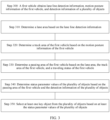
- an embodiment of this application provides a key target selection method.
- the method includes the following steps.
- Step 300 A first vehicle obtains lane line detection information, motion posture information of the first vehicle, and detection information of a plurality of objects.
- the first vehicle may obtain the lane line detection information, the motion posture information of the first vehicle, and the detection information of the plurality of objects by using the conventional technology. Details are not described herein again.
- Step 310 Determine a lane area based on the lane line detection information.
- the lane area includes an area (referred to as a current lane for short below) of a lane in which the first vehicle is located and an area other than the lane in which the first vehicle is located.
- the area other than the lane in which the first vehicle is located includes at least one of an area (referred to as a left lane for short below) of a lane on the left of the lane in which the first vehicle is located or an area (referred to as a right lane for short below) of a lane on the right of the lane in which the first vehicle is located.
- the lane area includes the current lane, the left lane, and the right lane, it indicates that the lane area includes three lanes. If the lane area includes the current lane and the left lane, or the current lane and the right lane, it indicates that the lane area includes two lanes.
- This embodiment of this application may be applied to a three-lane scenario and a two-lane scenario, and may be further applied to a four-lane scenario or another multi-lane scenario. This is not limited in this application.
- Lane line detection information includes information about four lane lines: L1, L2, L3, and L4.
- L1 a lane line that is closest to the left of a first vehicle
- L2 a lane line that is closest to the right of the first vehicle
- L3 a lane line that is second closest to the left of the first vehicle
- L4 a lane line that is second closest to the right of the first vehicle
- FIG. 4 shows a lane area determined when three-lane four-wire detection is effective. It is assumed that the lane line detection information includes the left lane line L1, the right lane line L2, the further left lane line L3, and the further right lane line L4, and the lane line detection information reports a correct location (which may also be referred to as effective detection). That the lane line detection information reports the correct location or the effective detection means that a correspondence between a lane line location output by a vehicle-mounted sensor and a location in which a true lane line is located is correct.
- the lane line detection information includes information about three lane lines.
- the left lane line is invisible and the right lane line is invisible.
- the lane line detection information includes information about two lane lines.
- a location of the left lane line is re-determined, and a distance between the left lane line obtained after re-determining and the first vehicle meets the preset condition.
- An area enclosed by the left lane line obtained after re-determining and the right lane line is an area of a lane in which the first vehicle is located, and an area enclosed by the left lane line obtained before re-determining and the left lane line obtained after re-determining is an area of a lane on the left of the lane in which the first vehicle is located.
- the first preset range may be [twice a lane width - a preset offset value, twice the lane width + the preset offset value].
- the preset offset value may be set based on an empirical value, for example, 0.2 m.
- the preset offset value is related to an error in detecting a lane line horizontal distance by the vehicle-mounted sensor.
- the preset condition may be determined based on a vehicle width and the lane width, and may be specifically set based on the empirical value. That the distance between the right lane line and the first vehicle meets the preset condition indicates that the right lane line reports a correct location or effective detection.
- the left lane line and the right lane line falls within the first preset range, and the distance between the right lane line and the first vehicle meets the preset condition, it can be learned that the left lane line reports an incorrect location or ineffective detection, and the current left lane line is supposed to be a further left lane line. Further, the location of the left lane line is re-determined, so that the distance between the left lane line obtained after re-determining and the first vehicle meets the preset condition. To be specific, the location of the left lane line is corrected, so that an accurate lane area can be obtained. It should be understood that the preset offset value 0.2 m is specific selection in this embodiment, and a person skilled in the art may also select another preset offset value (for example, 0.1 m or 0.3 m) based on an actual situation.
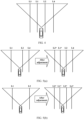
- left lane line detection is ineffective. It is assumed that the first preset range is [twice the lane width - 0.2 m, twice the lane width + 0.2 m], and the lane line detection information is reported only for L1, L2, and L4. It is verified that a distance between L1 and L2 is twice the lane width, so that the distance falls within the first preset range, a distance between L1 and the first vehicle does not meet the preset condition, and a distance between L2 and the first vehicle meets the preset condition, as shown in the schematic diagram on the left of FIG. 5(a) . Therefore, it is determined that L1 detection is ineffective, L1 is a false left lane line, and L2 is a real right lane line. In this case, a left lane line L1* may be deduced based on L2, and L1 is set as a further left lane line L3*, as shown in the schematic diagram on the right of FIG. 5(a) .
- An area enclosed by the left lane line and the right lane line obtained after re-determining is an area of the lane in which the first vehicle is located, and an area enclosed by the right lane line obtained before re-determining and the right lane line obtained after re-determining is an area of a lane on the right of the lane in which the first vehicle is located.
- the first preset range and the preset condition refer to related descriptions in the first possible design. No repeated description is provided. That the distance between the left lane line and the first vehicle meets the preset condition indicates that the left lane line reports a correct location or effective detection. Therefore, if the distance between the left lane line and the right lane line falls within the first preset range, and the distance between the left lane line and the first vehicle meets the preset condition, it can be learned that the right lane line reports an incorrect location or ineffective detection, and the current right lane line is supposed to be a further right lane line. Further, the location of the right lane line is re-determined, so that the distance between the right lane line obtained after re-determining and the first vehicle meets the preset condition. To be specific, the location of the right lane line is corrected, so that an accurate lane area can be obtained.
- An area enclosed by the left lane line obtained after re-determining and the right lane line obtained after re-determining is an area of a lane in which the first vehicle is located
- an area enclosed by the right lane line obtained before re-determining and the right lane line obtained after re-determining is an area of a lane on the right of the lane in which the first vehicle is located
- an area enclosed by the left lane line obtained before re-determining and the left lane line obtained after re-determining is an area of a lane on the left of the lane in which the first vehicle is located.
- the second preset range may be [three times the lane width - the preset offset value, three times the lane width + the preset offset value].
- the preset offset value may be set based on an empirical value. For details, refer to the first possible design.
- the preset condition may be determined based on the vehicle width and the lane width, and may be specifically set based on the empirical value. That the distance between the left lane line and the right lane line falls within the second preset range indicates that both the left lane line and the right lane line report incorrect positions or ineffective detection, the current left lane line is supposed to be the further left lane line, and the current right lane line is supposed to be the further right lane line.
- the locations of the left lane line and the right lane line are re-determined, so that the distance between the left lane line obtained after re-determining and the first vehicle meets the preset condition, and the distance between the right lane line obtained after re-determining and the first vehicle meets the preset condition.
- the locations of the left lane line and the right lane line are corrected, so that accurate lane areas can be obtained. For example, as shown in the schematic diagram on the left of FIG. 5(b) , the lane line detection information is reported only for L1 and L2. It is verified that the distance between L1 and L2 is three times the lane width, so that the distance falls within the second preset range.
- L1 is a false left lane line
- L2 is a false right lane line.
- the left lane line L1* and a right lane line L2* may be deduced, L1 is set as the further left lane line L3*, and L2 is set as a further right lane line L4*.
- step 320 is performed.
- Step 320 Determine a track area of the first vehicle based on the motion posture information of the first vehicle.
- the determining a track area of the first vehicle may specifically include the following steps: Step 1: Determine an original track area of the first vehicle.
- a moving track of the first vehicle may be determined based on the motion posture information of the first vehicle, and the original track area is determined based on the moving track of the first vehicle and a preset extension width.
- a vehicle coordinate system may be defined according to the ISO 8855 standard.
- a y axis is a horizontal location of the first vehicle, and a left side of the first vehicle is a positive direction of the y axis.
- An x axis is a longitudinal location of the first vehicle, and a traveling direction of the first vehicle is a positive direction of the x axis.
- ⁇ is a turning curvature
- ⁇ is a curvature change rate
- v x is a longitudinal speed of the first vehicle
- a x is a longitudinal acceleration of the first vehicle
- t is time.
- the foregoing parameters may be provided by the motion posture information of the first vehicle.
- FIG. 6 is a schematic diagram of a moving track of the first vehicle.
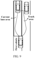
- a preset extension distance B is separately extended towards two sides in a direction of the horizontal location of the first vehicle, to obtain the original track area, as shown in FIG. 7 .
- B may be set based on the empirical value. For example, a value of B is greater than a half vehicle width and less than a half lane width. For example, it is assumed that a typical vehicle width is 1.8 m, and a typical lane width is 3.5 m. In this case, 0.9 ⁇ B ⁇ 1.75. To be specific, for example, B may be 1.2 m. Equations of a left boundary and a right boundary of the original track area are as follows.
- Step 2 Adjust the original track area to determine the track area of the first vehicle.
- a longitudinal maximum distance x max corresponding to the first vehicle and a longitudinal cut-in distance x cut corresponding to the first vehicle may be determined based on the motion posture information of the first vehicle.
- the longitudinal maximum distance x max indicates a range in which traveling of the first vehicle may be affected at a current speed of the first vehicle.
- the longitudinal cut-in distance x cut indicates a possible location at which another object vertically cuts in the lane in which the first vehicle is located. Based on this, the track area of the first vehicle may be determined by using any one of the following solutions:
- the following uses the solution 3 as an example to describe a specific process in which the first vehicle adjusts the original track area, to determine the track area of the first vehicle.
- THW a relative distance between two points that are of the first vehicle and that are closest to the object/the current speed v ego of the first vehicle. THW indicates how long the first vehicle takes to travel to the location at which the object is located at a current moment.
- THW may be adjusted and set by a driver through a human machine interface, and a value range of THW may be 1.0s to 2.5s.
- THW is related to factors such as different ages and different driving styles of the drivers, and the value range of THW may be 0.8s to 2s.
- the longitudinal cut-in distance x cut is determined based on the current speed v ego of the first vehicle.
- a correspondence between the longitudinal cut-in distance x cut and a vehicle speed when the another object vertically cuts in the current lane from another lane may be calibrated by using a method for real vehicle test or data statistics.
- a calibrated correspondence may form a calibration lookup table.
- the first vehicle stores in advance the correspondence used to indicate the vehicle speed and the longitudinal cut-in distance x cut .
- MAP is the calibration lookup table, and the calibration lookup table may be obtained based on the real vehicle test or data statistics.
- the MAP may be shown in Table 1.
- track boundary points corresponding to the longitudinal maximum distance x max in the original track area are respectively defined as a left inward contraction point and a right inward contraction point, and horizontal distances corresponding to the two inward contraction points are reduced inward by a first preset value, that is, adjusted from the preset extension distance B to the extension width corresponding to the longitudinal maximum distance.
- a value range of the first preset value herein may be 0.5 m to 1 m.
- track boundary points corresponding to the longitudinal cut-in distance x cut in the original track area are respectively defined as a left outward extension point and a right outward extension point, and horizontal distances corresponding to the two outward extension points are increased outward by a second preset value, that is, adjusted from the preset extension distance B to the extension width corresponding to the longitudinal cut-in distance.
- the second preset value herein may be 0.2 m to 1 m. A larger second preset value is more conservative and secure, and a smaller second preset value is more radical and efficient.
- a first segment of the track boundary is obtained through division from a start point to the outer extension points
- a second segment of the track boundary is obtained through division from the outer extension points to the inward contraction points
- the horizontal distance is adjusted by using an interpolation method, to obtain the track area of the first vehicle shown in FIG. 8 .
- the interpolation method may be a linear interpolation method or a spline curve interpolation method. This is not limited in this application.
- the track area that can be obtained by using the foregoing solution is a fusiform area.
- the foregoing part describes a technical process of the step 320 in FIG. 3 .
- a location at which another object may cut in the lane in which the first vehicle is located and a longitudinal distance range that is greatly affected by the object are relatively comprehensively considered, which helps select a key object while considering safety of the first vehicle.
- step 330 is performed.
- Step 330 Determine a passing area of the first vehicle based on the lane area, the track area of the first vehicle, and a traveling status of the first vehicle.
- the following describes, for different traveling statuses of the first vehicle, the passing area that is of the first vehicle and that corresponds to each traveling status.
- the first vehicle may determine, by using but not limited to the following method, that the traveling status of the first vehicle is a status in which the first vehicle travels on the lane line.
- the first vehicle When the first vehicle remains in a first status or a second status for more than first preset duration, it is determined that the first vehicle has the traveling status in which the first vehicle travels on the lane line.
- the first status an included angle between a head center line of the first vehicle and the left lane line is less than a first preset threshold, and a vertical distance from a head center point of the first vehicle to the left lane line is less than a second preset threshold.
- the second status an included angle between the head center line of the first vehicle and the right lane line is less than the first preset threshold, and a vertical distance from the head center point of the first vehicle to the right lane line is less than the second preset threshold.
- the passing area of the first vehicle is a target lane obtained after lane change of the first vehicle, and a longitudinal length of the passing area of the first vehicle is determined based on the longitudinal maximum distance.
- the first vehicle may determine, by using the following method, that the traveling status of the first vehicle is a status in which the first vehicle performs lane change but does not cross the lane line.
- the first vehicle When the first vehicle remains in a third status or a fourth status for more than second preset duration, it is determined that the first vehicle has the traveling status in which the first vehicle performs lane change but does not cross the lane line.
- an included angle between a head center line of the first vehicle and the left lane line is greater than a third preset threshold, a vertical distance from a head center point of the first vehicle to the left lane line decreases and is greater than 0, and a vertical distance from the head center point of the first vehicle to the right lane line increases and is less than a preset lane width.
- an included angle between the head center line of the first vehicle and the right lane line is greater than the third preset threshold, a vertical distance from the head center point of the first vehicle to the right lane line decreases and is greater than 0, and a vertical distance from the head center point of the first vehicle to the left lane line increases and is less than the preset lane width.
- the head center line is used as an example to determine the traveling status of the first vehicle. It may be understood that, during actual application, the solution is not limited to the head center line.
- the passing area of the first vehicle is the area of the lane in which the first vehicle is located.
- the passing area of the first vehicle is an area of a lane (which may also be described as a target lane) obtained after lane change, and a longitudinal length of the passing area of the first vehicle is determined based on the longitudinal maximum distance.
- the first vehicle may determine, by using but not limited to the following method, that the traveling status of the first vehicle is a status in which the first vehicle performs lane change and crosses the lane line.
- a lane line detection periodicity when a vertical distance from a head center point of the first vehicle to the left lane line suddenly changes from a preset lane width to 0, and a vertical distance from the head center point of the first vehicle to the right lane line suddenly changes from 0 to the preset lane width, it is determined that the first vehicle performs lane change to the left lane and crosses the left lane line.
- a vertical distance from a head center point of the first vehicle to the left lane line suddenly changes from 0 to a preset lane width
- a vertical distance from the head center point of the first vehicle to the right lane line suddenly changes from the preset lane width to 0
- the foregoing equation is a lane line detection equation, and a Clothoid curve is used.
- the item C 0 indicates the horizontal distance from the lane line to the head center point.
- the item C 1 indicates an included angle between the lane line and a longitudinal axis of the vehicle (or described as the head center point).
- the item C 2 indicates a curvature of the lane line.
- the item C 3 indicates a curvature change rate of the lane line.
- a width of the first vehicle is A
- the first threshold has a value range of [ A 2 ⁇ 0.2 , A 2 + 0.2 ], for example, may be A 2
- the second threshold has a value range of 0.8 ° ⁇ 1.5° , for example, may be 1°
- the first preset duration has a value range of 2s to 5s, for example, may be 2s.
- ⁇ l atan C 1 l
- ⁇ r atan C 1 r
- ⁇ l ⁇ r
- a value range of the second threshold is 1.5° to 2.5°, for example, 2 ° .
- a value range of the second preset duration is 0.1s to 0.3s, for example, 0.2s.
- the lane line detection periodicity is usually about 60 ms.
- the lane line detection periodicity may alternatively be any proper value in a range of 40 ms or 100 ms. This is not limited in this application.
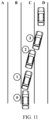
- the following describes, with reference to FIG. 11 , the passing areas of the first vehicle that respectively correspond to the different traveling statuses of the first vehicle.
- the traveling status of the first vehicle corresponding to a location 0 is a status in which the first vehicle travels in the current lane.
- the passing area of the first vehicle is the current lane, that is, a traveling area delimited by B and C, and the longitudinal length of the passing area of the first vehicle is the longitudinal maximum distance.
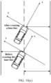
- the traveling status of the first vehicle corresponding to a location 1 is a status in which the first vehicle performs lane change but does not cross the lane lines.
- the passing area of the first vehicle is the target lane, that is, a traveling area delimited by C and D, and the longitudinal length of the passing area of the first vehicle is the longitudinal maximum distance.
- the traveling status of the first vehicle corresponding to a location 2 is a status in which the first vehicle performs lane change and crosses the lane lines.
- the passing area of the first vehicle is the current lane, that is, the area delimited by C and D
- the longitudinal length of the passing area of the first vehicle is the longitudinal maximum distance.
- the traveling status of the first vehicle corresponding to a location 3 is a status in which the first vehicle travels in the current lane.
- the first vehicle has completed lane change
- the passing area of the first vehicle is the current lane, that is, the area delimited by C and D
- the longitudinal length of the passing area of the first vehicle is the longitudinal maximum distance.
- the foregoing part describes a technical process of the step 320 in FIG. 3 .
- a plurality of possible scenarios in which the first vehicle travels are considered, to provide a reference background for implementing key object selection in various scenarios.
- step 340 is performed.
- Step 340 Determine status parameter values of the plurality of objects based on the passing area of the first vehicle and the detection information of the plurality of objects.
- the status parameter value of each object is used to indicate a degree of overlapping between the object and the passing area of the first vehicle.
- the following uses detection information of any object in the detection information of the plurality of objects as an example for description. The following cases are included.
- a vertical distance between a center point of the object and a left boundary of the passing area of the first vehicle is determined based on the passing area of the first vehicle and the detection information of the object. Further, the status parameter value of the object is determined based on the vertical distance between the center point of the object and the left boundary of the passing area of the first vehicle, a distance between the center point of the object and the head center line of the first vehicle, and a width of the object.
- a vertical distance between a center point of the object and a right boundary of the passing area of the first vehicle is determined based on the passing area of the first vehicle and the detection information of the object. Further, the status parameter value of the object is calculated based on the vertical distance between the center point of the object and the right boundary of the passing area of the first vehicle, a distance between the center point of the object and the head center line of the first vehicle, and a width of the object.
- a vertical distance between the center point of the object and a right boundary of the passing area of the first vehicle is determined based on the passing area of the first vehicle and the detection information of the object. Further, the status parameter value of the object is determined based on the vertical distance between the center point of the object and the right boundary of the passing area of the first vehicle, and a width of the object.
- the vertical distance between the center point of the object and the right boundary of the passing area of the first vehicle in the foregoing solution herein may also be replaced with the vertical distance between the center point of the object and the left boundary of the passing area of the first vehicle.
- center point of the object may alternatively be a tail center point of the object, a head center point of the object, a geometric center point of the object, a detection point that is of the object and that is closest to the first vehicle, or the like. This is not limited in this application.
- the status parameter value of the object may be calculated by using but is not limited to the following method.
- Step 1 Determine, based on a positive or negative horizontal relative distance y V of the object, whether the object is on the left side or the right side of the first vehicle. If the horizontal relative distance y V of the object is positive, the object is on the left side of the first vehicle, and a value of y V is equal to a value of a vertical distance between the center point of the object and the center line of the first vehicle. If the horizontal relative distance y V of the object is negative, the object is on the right side of the first vehicle, and a value of y V is equal to an opposite number of the value of the vertical distance between the center point of the object and the center line of the first vehicle.
- a vehicle coordinate system may be defined according to the ISO 8855 standard.
- a y axis is a horizontal location of the first vehicle, and a left side of the first vehicle is a positive direction of the y axis.
- An x axis is a longitudinal location of the first vehicle, and a traveling direction of the first vehicle is a positive direction of the x axis.
- w obj is the width of the object, and a value of a left horizontal boundary distance y VL corresponding to the object is a value of a distance between the head center point of the first vehicle and the left boundary of the passing area of the first vehicle.
- the status parameter value of the object w occ ⁇ y VR ⁇ 100 %
- an overlapping width w occ between the object and the first vehicle ⁇ y VR + y V + w obj 2
- w obj is the width of the object
- a value of a right horizontal boundary distance y VR corresponding to the object is an opposite number of a value of a distance between the head center point of the first vehicle and the right boundary of the passing area of the first vehicle.
- the overlapping width between the object and the first vehicle is calculated based on a predicted track line of the first vehicle extending to the object.
- step 1 For specific content of step 1, refer to the specific content of the step 1 in the foregoing example 1. Repeated content is not described again.
- the overlapping width w occ between the object and the first vehicle y VL ⁇ y V + w obj 2 .
- w obj is the width of the object
- the value of the left horizontal boundary distance y VL corresponding to the object is the value of the distance between the head center point of the first vehicle and the left boundary of the passing area of the first vehicle.
- the overlapping width w occ between the object and the first vehicle ⁇ y VR + y V + w obj 2 .
- w obj is the width of the object, and the value of the right horizontal boundary distance y VR corresponding to the object is the opposite number of the value of the distance between the head center point of the first vehicle and the right boundary of the passing area of the first vehicle.
- the method 1 and the method 2 are merely examples, and are not intended to limit this application.
- the vehicle coordinate system is used, but another coordinate system, for example, a Frenet coordinate system, may also be used.
- Example 1 As shown in FIG. 12 , a rectangular coordinate system is established by using the center line of the first vehicle as an x axis and a direction perpendicular to the center line of the first vehicle as a y axis.
- y is the horizontal location of the first vehicle, and a left direction is a positive direction.
- x is the longitudinal location of the first vehicle, and a forward direction is a positive direction.
- the passing area of the first vehicle is the current lane.
- y VL and y V 1 that correspond to a vehicle 1 and y VR and y V2 that correspond to a vehicle 2 are marked.
- This example may simultaneously adapt to the foregoing parameters y VL , y V , and y VR obtained in different scenarios in which the vehicle travels on a straight lane and a curve.
- a specific technical solution is as follows.
- v ego is a resultant velocity of the first vehicle
- a ego is a resultant acceleration of the first vehicle
- the coordinate system is converted from a current location (0, 0) to (x a , y a ), and a horizontal distance of the object relative to the predicted position is calculated in a new coordinate system.
- the coordinate system that uses the point (0, 0) as an origin is a vehicle body coordinate system of the current location
- the coordinate system that uses the point (x a , y a ) as an origin is a vehicle body coordinate system of the predicted position.
- the status parameter value of the object may be obtained based on the examples 1 and 2 and the methods 1 and 2.
- monitoring a change trend of the status parameter value of the object, and determining a motion status of the object based on the change trend of the status parameter value of the object and the preset condition include: When the object is located in the lane in which the first vehicle is located, a head of the object faces leftward, and a condition A is met, it is determined that the object has the motion status in which the object cuts out of the lane in which the first vehicle is located to the lane on the left of the lane in which the first vehicle is located.
- the object when the object is located in the lane in which the first vehicle is located, a head of the object faces rightward, and a condition A is met, it is determined that the object has the motion status in which the object cuts out of the lane in which the first vehicle is located to the lane on the right of the lane in which the first vehicle is located.
- the object when the object is located in a lane on the left of the lane in which the first vehicle is located, a head of the object faces rightward, and a condition B is met, it is determined that the object has the motion status in which the object cuts in the lane in which the first vehicle is located from the lane on the left of the lane in which the first vehicle is located.
- the object when the object is located in a lane on the right of the lane in which the first vehicle is located, a head of the object faces leftward, and a condition B is met, it is determined that the object has the motion status in which the object cuts in the lane in which the first vehicle is located from the lane on the right of the lane in which the first vehicle is located.
- a lane in which the object is located and an orientation of the head of the object may be determined based on the detection information of the object.
- the condition A includes: the status parameter value of the object gradually decreases and exceeds third preset duration, and an accumulated decrement of the status parameter value of the object exceeds a fourth preset threshold.
- the condition B includes: the status parameter value of the object gradually increases and exceeds fourth preset duration, and an accumulated increment of the status parameter value of the object exceeds a fifth preset threshold.
- a value range of the third preset duration is 100 ms to 300 ms, for example, may be 100 ms. Longer third preset duration indicates later time for cut-out object recognition, and is more conservative and secure.
- a value range of the fourth preset threshold is 20% to 50%. For example, the fourth preset threshold may be 30%. A larger fourth preset threshold indicates later time for cut-out object recognition, and is more conservative and secure.
- a value range of the fourth preset duration is 50 ms to 200 ms, for example, may be 100 ms. Longer fourth preset duration indicates later time for cut-in object recognition, and is more radical and efficient but less secure.
- a value range of the fifth preset threshold is 10% to 40%. For example, the fifth preset threshold may be 20%. A smaller fifth preset threshold indicates earlier time for cut-in object determining, and is more conservative and secure.
- the first vehicle may further determine, based on the foregoing determining, the lane in which the object is located.
- the condition C includes: the status parameter value of the object gradually decreases and exceeds fifth preset duration, and the accumulated decrement of the status parameter value of the object exceeds a sixth preset threshold.
- the condition D includes: the status parameter value of the object gradually increases and exceeds sixth preset duration, and the accumulated increment of the status parameter value corresponding to the object exceeds a seventh preset threshold.
- a value range of the fifth preset duration is 100 ms to 300 ms. Longer fifth preset duration indicates later time for determining that the object leaves the current lane, and is more secure and conservative but more inefficient.
- a value range of the sixth preset threshold is 80% to 100%. For example, the sixth preset threshold may be 90%. A larger sixth preset threshold is more secure and conservative but more inefficient.
- a value range of the sixth preset duration is 50 ms to 200 ms. Longer sixth preset duration indicates later time for determining that the cut-in object is classified into the current lane, and is more radical and efficient.
- a value range of the seventh preset threshold is 40% to 80%. For example, the seventh preset threshold may be 60%. A larger seventh preset threshold indicates later time for determining that the cut-in object is classified into the current lane, and is more radical and efficient but less secure.
- condition A to the condition D are merely examples, and a person skilled in the art makes modifications to the foregoing conditions without departing from the protection scope of this application as defined by the claims.
- FIG. 15 is a schematic diagram of determining, with reference to the foregoing condition A to condition D, the motion status of the object and the lane in which the object is located. According to the foregoing determining, the motion status of the object and the lane in which the object is located can be accurately obtained. Therefore, a strong support can be provided for key object selection.
- step 350 is performed.
- Step 350 Select at least one key object from the plurality of objects based on the status parameter values of the plurality of objects.
- At least one key object is determined from the plurality of objects based on the status parameter values of the plurality of objects and a longitudinal distance between each of the plurality of objects and the first vehicle.
- the scenario is a scenario in which an object that is performing lane change is not included.
- the object that is performing lane change includes at least one of the object that cuts out of the lane in which the first vehicle is located to the lane on the left of the lane in which the first vehicle is located, the object that cuts out of the lane in which the first vehicle is located to the lane on the right of the lane in which the first vehicle is located, the object that cuts in the lane in which the first vehicle is located from the lane on the left of the lane in which the first vehicle is located, and the object that cuts in the lane in which the first vehicle is located from the lane on the right of the lane in which the first vehicle is located.
- a static object and another vehicle that is traveling in the current lane are included.
- the following method may be used to select at least one key object from the plurality of objects.
- Target parameter values respectively corresponding to the plurality of objects are calculated.
- a target parameter value corresponding to each object is determined based on a first function value and a second function value.
- the first function value is determined based on the longitudinal distance between the object and the first vehicle and the longitudinal maximum distance. For example, a larger longitudinal distance between the object and the first vehicle indicates a smaller first function value.
- the second function value is determined based on the status parameter value of the object. For example, a larger status parameter value of the object indicates a larger second function value.
- different weights are separately configured for the first function value and the second function value, and then a weighted sum is calculated and used as the target parameter value corresponding to the object.
- the at least one key object is determined from the plurality of objects based on the target parameter values respectively corresponding to the plurality of objects. For example, the target parameter values are sorted, and objects corresponding to top three target parameter values with largest target parameter values are selected as the key objects, or an object whose target parameter value is greater than a preset threshold is used as the key object.
- p represents the status parameter value of the object
- f obj is a function used to select the key object.
- the function specifically includes a first function f(d x ) and a second function g(p).
- the first function is a function using the longitudinal distance between the target and the first vehicle as an independent variable
- the second function is a function using the status parameter value of the object as an independent variable.
- w 1 and w 2 are weights of f(d x ) and g(p) respectively. In particular, when w 1 is 0, the key object is selected only based on g(p).
- d x is the longitudinal distance between the object and the first vehicle
- x max is the longitudinal maximum distance corresponding to the first vehicle
- f obj corresponding to each of the plurality of objects may be calculated by using the foregoing formula, and an object corresponding to a maximum value of f obj is used as the key object.
- the at least one key object is selected from the plurality of objects based on the status parameter values of the plurality of objects, a longitudinal distance between each of the plurality of objects and the first vehicle, a motion status of at least one object in the plurality of objects, and a lane in which the at least one object is located.
- the motion status of the at least one object is a motion status of the object that is performing lane change.
- the scenario is a scenario in which the object that is performing lane change is included.
- the object that is performing lane change includes at least one of the object that cuts out of the lane in which the first vehicle is located to the lane on the left of the lane in which the first vehicle is located, the object that cuts out of the lane in which the first vehicle is located to the lane on the right of the lane in which the first vehicle is located, the object that cuts in the lane in which the first vehicle is located from the lane on the left of the lane in which the first vehicle is located, and the object that cuts in the lane in which the first vehicle is located from the lane on the right of the lane in which the first vehicle is located.
- a static object For example, in the current traveling scenario of the first vehicle, a static object, another vehicle traveling in the current lane, and a vehicle that cuts in the lane in which the first vehicle is located from the lane on the left of the lane in which the first vehicle is located are included.
- the following method may be used to select at least one key object from the plurality of objects.
- f obj corresponding to each object may be calculated with reference to the foregoing method, and the at least one key object is further selected from the plurality of objects with reference to the motion status of the object that is performing lane change and a lane in which the object that is performing lane change is located.
- a scenario a if an object A travels in the current lane, an object B travels in the left lane, an object C travels in the right lane, and the object B and the object C have no trend to switch between lanes (that is, p is 0), the object A is the key object.
- the scenario a does not include the object that is performing lane change.
- an object B is cutting in the current lane (which may be determined based on a change trend of p over time), and a longitudinal distance between the object B and the first vehicle is relatively small. Therefore, the object B is the key object.
- a scenario c although a longitudinal distance between the object A and the first vehicle is relatively small, the object A is cutting in the right lane (which may be determined based on a change trend of p over time). Therefore, the object C is the key object.
- the key object may be further selected with reference to another factor as a reference variable, for example, a current road condition, a weather condition, or a speed of the first vehicle. This is merely an example, and is not intended to limit this application.
- the first vehicle may display information about the key object through a human machine interface, or play the information about the key object by using a voice, to remind the driver to pay attention, to provide a reference for the driver to perform a correct control action on the first vehicle.
- the first vehicle may further notify the intelligent driving function unit shown in FIG. 1 of the determined key object, so that the intelligent driving function unit performs a correct control action on the first vehicle, for example, braking or deceleration.
- FIG. 17 is a schematic diagram of an example of displaying a key object on a human machine interface.
- the key object is marked by a circle, and the first vehicle is not included in FIG. 17.
- FIG. 17 shows vehicles in a traveling direction of the first vehicle.
- this application further provides an intelligent driving system.
- the system includes a vehicle end and a cloud server end.
- the vehicle end is located in a first vehicle.
- the cloud server end herein may be a physical server, or may be a virtual machine. This is not limited in this application.
- Step 310 to step 350 may be completed in the cloud server end, or some steps in step 310 to step 350 may be completed in the cloud server end.
- the vehicle end in the first vehicle may complete some steps of the foregoing method, and the cloud server end completes other steps of the foregoing method.
- FIG. 18 is a schematic diagram of interaction between a vehicle end and a cloud server end.
- the first vehicle may perform some or all of steps in embodiments of this application. These steps or operations are merely examples. In embodiments of this application, other operations or variations of various operations may be further performed. In addition, the steps may be performed in a sequence different from a sequence presented in embodiments of this application, and not all the operations in embodiments of this application may be necessarily to be performed.
- the intelligent driving system includes a corresponding hardware structure and/or software module for performing the functions.
- this application may be implemented by hardware or a combination of hardware and computer software. Whether a function is performed by hardware or hardware driven by computer software depends on particular applications and design constraints of the technical solutions. A person skilled in the art may use different methods to implement the described functions for each particular application.
- an embodiment of this application further provides an apparatus 1900.
- the apparatus 1900 includes an obtaining unit 1902 and a processing unit 1901.
- the apparatus 1900 is configured to implement functions of the first vehicle in the foregoing method.
- the apparatus may be the first vehicle or an intelligent driving system in the first vehicle.
- the obtaining unit 1902 is configured to obtain lane line detection information, motion posture information of a first vehicle, and detection information of a plurality of objects.
- the processing unit 1901 is configured to: determine a lane area based on the lane line detection information; determine a track area of the first vehicle based on the motion posture information of the first vehicle; determine a passing area of the first vehicle based on the lane area, the track area of the first vehicle, and a traveling status of the first vehicle; determine status parameter values of the plurality of objects based on the passing area of the first vehicle and the detection information of the plurality of objects, where the status parameter value of each object is used to indicate a degree of overlapping between the object and the passing area of the first vehicle; and select at least one key object from the plurality of objects based on at least the status parameter values of the plurality of objects.
- Division into the modules in embodiments of this application is an example, is merely division into logical functions, and may be other division during actual implementation.
- functional modules in embodiments of this application may be integrated into one processor, or each of the modules may exist alone physically, or two or more modules may be integrated into one module.
- the integrated module may be implemented in a form of hardware, or may be implemented in a form of a software function module.
- the apparatus may be a chip system.
- the chip system may include a chip, or may include a chip and another discrete component.
- the apparatus includes a processor and an interface, and the interface may be an input/output interface.
- the processor implements functions of the processing unit 1901, and the interface implements functions of the obtaining unit 1902.
- the apparatus may further include a memory.
- the memory is configured to store a program that may be run on the processor, and the processor implements the methods in the foregoing embodiments when executing the program.
- an embodiment of this application further provides an apparatus 2000.
- the apparatus 2000 includes a transceiver unit 2002 and a processing unit 2001.
- the apparatus 2000 is configured to implement functions of the first vehicle in the foregoing method.
- the apparatus may be a cloud server end.
- the transceiver unit 2002 is configured to receive lane line detection information from a first vehicle, motion posture information of the first vehicle, and detection information of a plurality of objects.
- the processing unit 2001 is configured to: determine a lane area based on the lane line detection information; determine a track area of the first vehicle based on the motion posture information of the first vehicle; determine a passing area of the first vehicle based on the lane area, the track area of the first vehicle, and a traveling status of the first vehicle; determine status parameter values of the plurality of objects based on the passing area of the first vehicle and the detection information of the plurality of objects, where the status parameter value of each object is used to indicate a degree of overlapping between the object and the passing area of the first vehicle; and select at least one key object from the plurality of objects based on at least the status parameter values of the plurality of objects.
- an embodiment of this application further provides an apparatus 2100.
- the apparatus 2100 includes a communication interface 2101, at least one processor 2102, and at least one memory 2103.
- the communication interface 2101 is configured to communicate with another device via a transmission medium, so that an apparatus in the apparatus 2100 can communicate with the another device.
- the memory 2103 is configured to store a computer program.
- the processor 2102 invokes the computer program stored in the memory 2103, to send and receive data through the communication interface 2101, to perform the method according to any one of the foregoing embodiments.
- the memory 2103 is configured to store the computer program.
- the processor 2102 invokes the computer program stored in the memory 2103, to perform, through the communication interface 2101, the methods performed by the first vehicle in the foregoing embodiments.
- the communication interface 2101 may be a transceiver, a circuit, a bus, a module, or a communication interface of another type.
- the processor 2102 may be a general-purpose processor, a digital signal processor, an application-specific integrated circuit, a field programmable gate array or another programmable logic device, a discrete gate or transistor logic device, or a discrete hardware component, and may implement or perform the methods, steps, and logical block diagrams disclosed in embodiments of this application.
- the general-purpose processor may be a microprocessor, any conventional processor, or the like. The steps of the method disclosed with reference to embodiments of this application may be directly performed by a hardware processor, or may be performed by using a combination of hardware in the processor and a software module.
- the memory 2103 may be a nonvolatile memory, for example, a hard disk drive (hard disk drive, HDD) or a solid-state drive (solid-state drive, SSD), or may be a volatile memory (volatile memory), for example, a random access memory (random access memory, RAM).
- the memory is any other medium that can carry or store expected program code in a form of an instruction or a data structure and that can be accessed by a computer, but is not limited thereto.
- the memory in this embodiment of this application may alternatively be a circuit or any other apparatus that can implement a storage function.
- the memory 2103 is coupled to the processor 2102.
- Coupling in this embodiment of this application is indirect coupling or a communication connection between apparatuses, units, or modules, may be in an electrical form, a mechanical form, or another form, and is used for information exchange between apparatuses, units, or modules.
- the memory 2103 may alternatively be located outside the apparatus 2100.
- the processor 2102 may cooperate with the memory 2103.
- the processor 2102 may execute program instructions stored in the memory 2103.
- At least one of the at least one memory 2103 may alternatively be included in the processor 2102.
- a connection medium among the communication interface 2101, the processor 2102, and the memory 2103 is not limited.
- the memory 2103, the processor 2102, and the communication interface 2101 may be connected through a bus in FIG. 21 .
- the bus may be classified into an address bus, a data bus, a control bus, or the like.
- the apparatus in the embodiment shown in FIG. 19 may be implemented by the apparatus 2100 shown in FIG. 21 .
- the processing unit 1901 may be implemented by the processor 2102
- the obtaining unit 1902 may be implemented by the communication interface 2101.
- the apparatus in the embodiment shown in FIG. 20 may be implemented by the apparatus 2100 shown in FIG. 21 .
- the processing unit 2001 may be implemented by the processor 2102
- the obtaining unit 2002 may be implemented by the communication interface 2101.
- An embodiment of this application further provides a readable storage medium.
- the readable storage medium stores a computer program.
- the computer program When the computer program is run on a device, the device is enabled to perform the method according to any one of the foregoing embodiments.
- All or some of the methods in embodiments of this application may be implemented through software, hardware, firmware, or any combination thereof.
- the software is used to implement embodiments, all or some of embodiments may be implemented in a form of a computer program product.
- the computer program product includes one or more computer instructions.
- the computer may be a general-purpose computer, a dedicated computer, a computer network, a network device, user equipment, or another programmable apparatus.
- the computer instructions may be stored in a computer-readable storage medium or may be transmitted from a computer-readable storage medium to another computer-readable storage medium.
- the computer instructions may be transmitted from a website, computer, server, or data center to another website, computer, server, or data center in a wired (for example, a coaxial cable, an optical fiber, or a digital subscriber line (digital subscriber line, DSL for short)) or wireless (for example, infrared, radio, or microwave) manner.
- the computer-readable storage medium may be any usable medium accessible by a computer, or a data storage device, such as a server or a data center, integrating one or more usable media.
- the usable medium may be a magnetic medium (for example, a floppy disk, a hard disk, or a magnetic tape), an optical medium (for example, a digital video disc (digital video disc, DVD)), a semiconductor medium (for example, a solid-state drive (Solid State Disk, SSD)), or the like.
- a magnetic medium for example, a floppy disk, a hard disk, or a magnetic tape
- an optical medium for example, a digital video disc (digital video disc, DVD)
- a semiconductor medium for example, a solid-state drive (Solid State Disk, SSD)
Landscapes
- Engineering & Computer Science (AREA)
- Automation & Control Theory (AREA)
- Transportation (AREA)
- Mechanical Engineering (AREA)
- Traffic Control Systems (AREA)
Claims (15)
- Schlüsselobjekt-Auswahlverfahren, wobei das Verfahren Folgendes umfasst:Erlangen (300) von Fahrbahnlinienerkennungsinformationen, Bewegungspositionsinformationen eines ersten Fahrzeugs und Erkennungsinformationen einer Vielzahl von Objekten;Bestimmen (310) eines Fahrbahnbereichs auf Grundlage der Fahrbahnlinienerkennungsinformationen und Bestimmen (320) eines Streckenbereichs des ersten Fahrzeugs auf Grundlage der Bewegungspositionsinformationen des ersten Fahrzeugs;Bestimmen (330) eines Überholbereichs des ersten Fahrzeugs auf Grundlage des Fahrbahnbereichs, des Streckenbereichs des ersten Fahrzeugs und einem Fahrtstatus des ersten Fahrzeugs;Bestimmen (340) von Statusparameterwerten der Vielzahl von Objekten auf Grundlage des Überholbereichs des ersten Fahrzeugs und der Erkennungsinformationen der Vielzahl von Objekten, wobei der Statusparameterwert jedes Objekts verwendet wird, um einen Überlappungsgrad zwischen dem Objekt und dem Überholbereich des ersten Fahrzeugs anzugeben; undAuswählen (350) von mindestens einem Schlüsselobjekt aus der Vielzahl von Objekten auf Grundlage von mindestens den Statusparameterwerten der Vielzahl von Objekten.
- Verfahren nach Anspruch 1, wobei der Fahrbahnbereich einen Bereich einer Fahrbahn, in der sich das erste Fahrzeug befindet, und einen anderen Bereich als die Fahrbahn, in der sich das erste Fahrzeug befindet, umfasst, und der andere Bereich als die Fahrbahn, in der sich das erste Fahrzeug befindet, mindestens einen Bereich einer Fahrbahn links von der Fahrbahn, in der sich das erste Fahrzeug befindet, und einen Bereich einer Fahrbahn rechts von der Fahrbahn, in der sich das erste Fahrzeug befindet, umfasst.
- Verfahren nach Anspruch 2, ferner umfassend:
Neubestimmen des Fahrbahnbereichs, wenn mindestens eines einer Vielzahl der folgenden Ereignisse auf Grundlage der Fahrbahnlinienerkennungsinformationen bestimmt wird, wobei die Vielzahl von Ereignissen Folgendes umfasst: ein Abstand zwischen einer linken Fahrbahnlinie und einer rechten Fahrbahnlinie erfüllt nicht eine erste vorgegebene Bedingung, ein Abstand zwischen der linken Fahrbahnlinie und dem ersten Fahrzeug erfüllt nicht eine zweite vorgegebene Bedingung und ein Abstand zwischen der rechten Fahrbahnlinie und dem ersten Fahrzeug erfüllt nicht die zweite vorgegebene Bedingung. - Verfahren nach einem der Ansprüche 1 bis 3, wobei der Fahrstatus des ersten Fahrzeugs eines oder mehrere von Folgendem umfasst: das erste Fahrzeug fährt in einem Bereich ohne Fahrbahnlinie, das erste Fahrzeug fährt auf der Fahrbahn, auf der sich das erste Fahrzeug befindet, das erste Fahrzeug fährt auf der Fahrbahnlinie, das erste Fahrzeug führt einen Fahrbahnwechsel durch, überquert die Fahrbahnlinie jedoch nicht, und das erste Fahrzeug führt einen Fahrbahnwechsel durch und überquert die Fahrbahnlinie.
- Verfahren nach Anspruch 4, ferner Folgendes umfassend:wenn das erste Fahrzeug länger als die erste vorgegebene Dauer in einem ersten Status oder einem zweiten Status verbleibt, Bestimmen, dass das erste Fahrzeug den Fahrstatus hat, in dem das erste Fahrzeug auf der Fahrbahnlinie fährt, wobeiim ersten Status ein eingeschlossener Winkel zwischen einer Kopfmittellinie des ersten Fahrzeugs und einer linken Fahrbahnlinie kleiner als ein erster vorgegebener Schwellenwert und ein vertikaler Abstand von einem Kopfmittelpunkt des ersten Fahrzeugs zu der linken Fahrbahnlinie kleiner als ein zweiter vorgegebener Schwellenwert ist; und im zweiten Status ein eingeschlossener Winkel zwischen der Kopfmittellinie des ersten Fahrzeugs und einer rechten Fahrbahnlinie kleiner als der erste vorgegebene Schwellenwert und ein vertikaler Abstand von dem Kopfmittelpunkt des ersten Fahrzeugs zu der rechten Fahrbahnlinie kleiner als der zweite vorgegebene Schwellenwert ist.
- Verfahren nach Anspruch 4, ferner Folgendes umfassend:wenn das erste Fahrzeug länger als eine zweite vorgegebene Dauer in einem dritten Status oder einem vierten Status verbleibt, Bestimmen, dass das erste Fahrzeug den Fahrstatus hat, in dem das erste Fahrzeug einen Fahrbahnwechsel durchführt, aber die Fahrbahnlinie nicht überquert, wobeiim dritten Status ein eingeschlossener Winkel zwischen einer Kopfmittellinie des ersten Fahrzeugs und einer linken Fahrbahnlinie größer als ein dritter vorgegebener Schwellenwert ist, ein vertikaler Abstand von einem Kopfmittelpunkt des ersten Fahrzeugs zu der linken Fahrbahnlinie abnimmt und größer als 0 ist, und ein vertikaler Abstand von dem Kopfmittelpunkt des ersten Fahrzeugs zu einer rechten Fahrbahnlinie zunimmt und kleiner als eine vorgegebene Fahrbahnbreite ist; und im vierten Status ein eingeschlossener Winkel zwischen der Kopfmittellinie des ersten Fahrzeugs und der rechten Fahrbahnlinie größer als der dritte vorgegebene Schwellenwert ist, ein vertikaler Abstand von dem Kopfmittelpunkt des ersten Fahrzeugs zu der rechten Fahrbahnlinie abnimmt und größer als 0 ist, und ein vertikaler Abstand von dem Kopfmittelpunkt des ersten Fahrzeugs zu der linken Fahrbahnlinie zunimmt und kleiner als die voreingestellte Fahrbahnbreite ist.
- Verfahren nach Anspruch 4, ferner Folgendes umfassend:in einer Fahrbahnlinienerkennungsperiodizität, wenn sich ein vertikaler Abstand von einem Kopfmittelpunkt des ersten Fahrzeugs zu einer linken Fahrbahnlinie plötzlich von einer vorgegebenen Fahrbahnbreite auf 0 ändert und sich ein vertikaler Abstand von dem Kopfmittelpunkt des ersten Fahrzeugs zu einer rechten Fahrbahnlinie plötzlich von 0 auf die vorgegebene Fahrbahnbreite ändert, Bestimmen, dass sich das erste Fahrzeug in dem Fahrstatus befindet, in dem das erste Fahrzeug einen Fahrbahnwechsel durchführt und die Fahrbahnlinie überquert; oderin einer Fahrbahnlinienerkennungsperiodizität, wenn sich ein vertikaler Abstand von einem Kopfmittelpunkt des ersten Fahrzeugs zu einer linken Fahrbahnlinie plötzlich von 0 auf eine vorgegebene Fahrbahnbreite ändert und sich ein vertikaler Abstand von dem Kopfmittelpunkt des ersten Fahrzeugs zu einer rechten Fahrbahnlinie plötzlich von der vorgegebenen Fahrbahnbreite auf 0 ändert, Bestimmen, dass sich das erste Fahrzeug in dem Fahrstatus befindet, in dem das erste Fahrzeug einen Fahrbahnwechsel durchführt und die Fahrbahnlinie überquert.
- Verfahren nach einem der Ansprüche 1 bis 7, wobei das Bestimmen (320) eines Streckenbereichs des ersten Fahrzeugs auf Grundlage der Bewegungspositionsinformationen des ersten Fahrzeugs Folgendes umfasst:Bestimmen einer Fahrbahn des ersten Fahrzeugs auf Grundlage der Bewegungspositionsinformationen des ersten Fahrzeugs und Bestimmen eines ursprünglichen Streckenbereichs auf Grundlage der Fahrbahn des ersten Fahrzeugs und einer vorgegebenen Erweiterungsbreite;Bestimmen einer maximalen Längsdistanz und einer längsseitigen Einscherdistanz auf Grundlage der Bewegungspositionsinformationen des ersten Fahrzeugs, wobei die maximale Längsdistanz einen Bereich angibt, in dem die Fahrt des ersten Fahrzeugs zu einem aktuellen Zeitpunkt und bei einer aktuellen Geschwindigkeit des ersten Fahrzeugs beeinträchtigt werden kann, und die längsseitige Einscherdistanz eine mögliche Stelle angibt, an der ein anderes Objekt vertikal in die Fahrbahn einschert, in der sich das erste Fahrzeug befindet; und Bestimmen der Streckenfläche des ersten Fahrzeugs auf Grundlage des ursprünglichen Streckenbereichs, der maximalen Längsdistanz, der längsseitigen Einscherdistanz und einer Erweiterungsbreite, die der längsseitigen Einscherdistanz entspricht, wobei die Erweiterungsbreite, die der längsseitigen Einscherdistanz entspricht, größer ist als die voreingestellte Erweiterungsbreite; oder Bestimmen des Streckenbereichs des ersten Fahrzeugs auf Grundlage des ursprünglichen Streckenbereichs, der maximalen Längsdistanz und einer Erweiterungsbreite, die der maximalen Längsdistanz entspricht, wobei die Erweiterungsbreite, die der maximalen Längsdistanz entspricht, kleiner als die vorgegebene Erweiterungsbreite ist.
- Verfahren nach Anspruch 8, wobei das Bestimmen eines Überholbereichs (330) des ersten Fahrzeugs auf Grundlage des Fahrbahnbereichs, des Streckenbereichs (320) des ersten Fahrzeugs und eines Fahrstatus des ersten Fahrzeugs Folgendes umfasst:wenn das erste Fahrzeug den Fahrstatus hat, in dem das erste Fahrzeug in dem Bereich ohne Fahrbahnlinie fährt, Bestimmen, dass der Überholbereich des ersten Fahrzeugs der Streckenbereich des ersten Fahrzeugs ist, und eine Längslänge des Überholbereichs des ersten Fahrzeugs auf Grundlage der maximalen Längsdistanz bestimmt wird;wenn das erste Fahrzeug den Fahrstatus hat, in dem das erste Fahrzeug auf der Fahrbahn fährt, auf der sich das erste Fahrzeug sich befindet, Bestimmen, dass der Überholbereich des ersten Fahrzeugs der Bereich der Fahrbahn ist, auf der sich die erste Fahrbahn befindet, und eine Längslänge des Überholbereichs des ersten Fahrzeugs auf Grundlage der maximalen Längsdistanz bestimmt wird;wenn das erste Fahrzeug den Fahrstatus hat, in dem das erste Fahrzeug auf der Fahrbahnlinie fährt, Bestimmen, dass der Überholbereich des ersten Fahrzeugs auf Grundlage des Bereichs der Fahrbahn, auf dem sich das erste Fahrzeug befindet, und des Streckenbereichs des ersten Fahrzeugs bestimmt wird, und eine Längslänge des Überholbereichs des ersten Fahrzeugs auf Grundlage der maximalen Längsdistanz bestimmt wird;wenn das erste Fahrzeug den Fahrstatus hat, in dem das erste Fahrzeug einen Fahrbahnwechsel durchführt, aber die Fahrbahnlinie nicht überquert, Bestimmen, dass der Überholbereich des ersten Fahrzeugs ein Bereich einer Zielfahrbahn ist, der nach dem Fahrbahnwechsel des ersten Fahrzeugs erlangt wurde, und eine Längslänge des Überholbereichs des ersten Fahrzeugs auf Grundlage der maximalen Längsdistanz bestimmt wird; oderwenn das erste Fahrzeug den Fahrstatus hat, in dem das erste Fahrzeug einen Fahrbahnwechsel durchführt und die Fahrbahnlinie überquert, Bestimmen, dass der Überholbereich des ersten Fahrzeugs der Bereich der Fahrbahn ist, in dem sich das erste Fahrzeug befindet, und eine Längslänge des Überholbereichs des ersten Fahrzeugs auf Grundlage der maximalen Längsdistanz bestimmt wird.
- Verfahren nach Anspruch 9, wobei das Bestimmen (340) von Statusparameterwerten der Vielzahl von Objekten auf Grundlage des Überholbereichs des ersten Fahrzeugs und der Erkennungsinformationen der Vielzahl von Objekten Folgendes umfasst:wenn auf Grundlage der Erkennungsinformationen eines Objekts in den Erkennungsinformationen der Vielzahl von Objekten bestimmt wird, dass sich das Objekt links vom ersten Fahrzeug befindet, Bestimmen eines vertikalen Abstands zwischen einem Mittelpunkt des Objekts und einer linken Grenze des Überholbereichs des ersten Fahrzeugs auf Grundlage des Überholbereichs des ersten Fahrzeugs und der Erkennungsinformationen des Objekts; undBestimmen des Statusparameterwerts des Objekts auf Grundlage des vertikalen Abstands zwischen dem Mittelpunkt des Objekts und der linken Grenze des Überholbereichs des ersten Fahrzeugs, einem Abstand zwischen dem Mittelpunkt des Objekts und der Kopfmittellinie des ersten Fahrzeugs und einer Breite des Objekts;wenn auf Grundlage von Erkennungsinformationen eines Objekts in den Erkennungsinformationen der Vielzahl von Objekten bestimmt wird, dass sich das Objekt rechten vom ersten Fahrzeug befindet, Bestimmen eines vertikalen Abstands zwischen einem Mittelpunkt des Objekts und einer rechten Grenze des Überholbereichs des ersten Fahrzeugs auf Grundlage des Überholbereichs des ersten Fahrzeugs und der Erkennungsinformationen des Objekts; undBestimmen des Statusparameterwerts des Objekts auf Grundlage des vertikalen Abstands zwischen dem Mittelpunkt des Objekts und der rechten Grenze des Überholbereichs des ersten Fahrzeugs, einem Abstand zwischen dem Mittelpunkt des Objekts und der Kopfmittellinie des ersten Fahrzeugs und einer Breite des Objekts;wenn auf Grundlage von Erkennungsinformationen eines Objekts in den Erkennungsinformationen der Vielzahl von Objekten bestimmt wird, dass ein Mittelpunkt des Objekts auf der Kopfmittellinie des ersten Fahrzeugs liegt, Bestimmen eines vertikalen Abstands zwischen dem Mittelpunkt des Objekts und einer rechten Grenze des Überholbereichs des ersten Fahrzeugs auf Grundlage des Überholbereichs des ersten Fahrzeugs und der Erkennungsinformationen des Objekts; und Bestimmen des Statusparameterwerts des Objekts auf Grundlage des vertikalen Abstands zwischen dem Mittelpunkt des Objekts und der rechten Grenze des Überholbereichs des ersten Fahrzeugs und einer Breite des Objekts.
- Verfahren nach Anspruch 10, ferner umfassend:Überwachen eines Änderungstrends des Statusparameterwerts des Objekts; undwenn bestimmt wird, dass die Änderungstendenz des Statusparameterwerts des Objekts eine vorgegebene Bedingung erfüllt, Bestimmen eines Bewegungsstatus des Objekts und einer Fahrbahn, auf der sich das Objekt befindet.
- Verfahren nach Anspruch 11, wobei das Auswählen von mindestens einem Schlüsselobjekt aus der Vielzahl von Objekten auf Grundlage von mindestens den Statusparameterwerten der Vielzahl von Objekten Folgendes umfasst:
Auswählen des mindestens einen Schlüsselobjekts aus der Vielzahl von Objekten auf Grundlage der Statusparameterwerte der Vielzahl von Objekten, eines Längsabstands zwischen jedem der Vielzahl von Objekten und dem ersten Fahrzeug, eines Bewegungsstatus von mindestens einem Objekt in der Vielzahl von Objekten und einer Fahrbahn, auf der sich das mindestens eine Objekt befindet. - Verfahren nach einem der Ansprüche 1 bis 12, ferner umfassend:Anzeigen von Informationen über das mindestens eine Schlüsselobjekt auf einer Mensch-Maschine-Schnittstelle des ersten Fahrzeugs; oderAuffordern eines Fahrers zur Bereitstellung der Informationen über das mindestens eine Schlüsselobjekt mittels einer Stimme.
- Vorrichtung (1900) zum Auswählen eines Schlüsselobjekts, wobei die Vorrichtung Folgendes umfasst:eine Erlangungseinheit (1902), die dazu konfiguriert ist, Fahrbahnlinienerkennungsinformationen,Bewegungspositionsinformationen eines ersten Fahrzeugs und Erkennungsinformationen einer Vielzahl von Objekten zu erlangen; undeine Verarbeitungseinheit (1901), die zu Folgendem konfiguriert ist: Bestimmen eines Fahrbahnbereichs auf Grundlage der Fahrbahnlinienerkennungsinformationen; Bestimmen eines Streckenbereichs des ersten Fahrzeugs auf Grundlage der Bewegungspositionsinformationen des ersten Fahrzeugs; Bestimmen eines Überholbereichs des ersten Fahrzeugs auf Grundlage des Fahrbahnbereichs, des Streckenbereichs des ersten Fahrzeugs und einem Fahrstatus des ersten Fahrzeugs; Bestimmen von Statusparameterwerten der Vielzahl von Objekten auf Grundlage des Überholbereichs des ersten Fahrzeugs und der Erkennungsinformationen der Vielzahl von Objekten, wobei der Statusparameterwert jedes Objekts verwendet wird, um einen Überlappungsgrad zwischen dem Objekt und dem Überholbereich des ersten Fahrzeugs anzugeben; und zum Auswählen von mindestens einem Schlüsselobjekt aus der Vielzahl von Objekten mindestens auf Grundlage der Statusparameterwerte der Vielzahl von Objekten.
- Computerlesbares Speichermedium, wobei das computerlesbare Speichermedium Programmieranweisungen umfasst, und wenn die Programmieranweisungen auf einer Vorrichtung ausgeführt werden, ist die Vorrichtung in der Lage, das Verfahren nach einem der Ansprüche 1 bis 13 durchzuführen.
Applications Claiming Priority (1)
| Application Number | Priority Date | Filing Date | Title |
|---|---|---|---|
| PCT/CN2020/082612 WO2021196041A1 (zh) | 2020-03-31 | 2020-03-31 | 一种关键目标选取方法、装置及系统 |
Publications (3)
| Publication Number | Publication Date |
|---|---|
| EP4129787A1 EP4129787A1 (de) | 2023-02-08 |
| EP4129787A4 EP4129787A4 (de) | 2023-06-07 |
| EP4129787B1 true EP4129787B1 (de) | 2025-05-14 |
Family
ID=77927192
Family Applications (1)
| Application Number | Title | Priority Date | Filing Date |
|---|---|---|---|
| EP20928310.0A Active EP4129787B1 (de) | 2020-03-31 | 2020-03-31 | Auswahlverfahren für ein schlüsselziel, vorrichtung und system |
Country Status (3)
| Country | Link |
|---|---|
| EP (1) | EP4129787B1 (de) |
| CN (1) | CN115087573B (de) |
| WO (1) | WO2021196041A1 (de) |
Families Citing this family (10)
| Publication number | Priority date | Publication date | Assignee | Title |
|---|---|---|---|---|
| KR20220114750A (ko) * | 2021-02-09 | 2022-08-17 | 현대모비스 주식회사 | 차선 인식 시스템 및 제어 방법 |
| CN114543828A (zh) * | 2022-02-21 | 2022-05-27 | 中国第一汽车股份有限公司 | 车辆切入场景生成方法、装置、电子设备及存储介质 |
| CN114882706B (zh) * | 2022-05-31 | 2023-06-16 | 华中科技大学 | 一种基于非结构性路面的周向防碰撞预警方法及系统 |
| CN115112114B (zh) * | 2022-06-15 | 2024-05-03 | 苏州轻棹科技有限公司 | 一种修正自车周围车辆朝向角的处理方法和装置 |
| CN115623037B (zh) * | 2022-09-28 | 2025-08-05 | 浙江吉利控股集团有限公司 | 传感器数据融合方法、设备及计算机可读存储介质 |
| CN116110216B (zh) * | 2022-10-21 | 2024-04-12 | 中国第一汽车股份有限公司 | 车辆跨线时间确定方法、装置、存储介质及电子装置 |
| CN116552518B (zh) * | 2023-06-25 | 2025-08-26 | 一汽解放汽车有限公司 | 一种变道目标预测方法、装置、电子设备及介质 |
| CN116749968B (zh) * | 2023-08-16 | 2023-11-03 | 知行汽车科技(苏州)股份有限公司 | 一种目标车辆的检测方法、装置、设备及介质 |
| CN119911284B (zh) * | 2023-10-30 | 2026-03-06 | 苏州挚途科技有限公司 | 车辆感兴趣目标置信度确定方法、装置及智能驾驶车辆 |
| CN117746362B (zh) * | 2023-12-05 | 2024-11-15 | 北京卓视智通科技有限责任公司 | 一种车辆连续变道检测方法、系统、存储介质和电子设备 |
Family Cites Families (18)
| Publication number | Priority date | Publication date | Assignee | Title |
|---|---|---|---|---|
| DE19637245C2 (de) * | 1996-09-13 | 2000-02-24 | Bosch Gmbh Robert | Verfahren und Vorrichtung zur Regelung der Geschwindigkeit eines Fahrzeugs |
| DE10254423A1 (de) * | 2002-11-21 | 2004-06-03 | Lucas Automotive Gmbh | System zur Beeinflussung der Geschwindigkeit eines Kraftfahrzeuges |
| JP5281664B2 (ja) * | 2011-02-23 | 2013-09-04 | クラリオン株式会社 | 車線逸脱警報装置および車線逸脱警報システム |
| DE102011102429A1 (de) * | 2011-05-25 | 2012-11-29 | Audi Ag | Verfahren zum Betrieb eines längsführenden Fahrassistenzsystems eines Kraftfahrzeugs und Kraftfahrzeug |
| JP5673597B2 (ja) * | 2011-11-18 | 2015-02-18 | 株式会社デンソー | 車両用挙動制御装置 |
| DE102013013867A1 (de) * | 2013-08-20 | 2015-03-12 | Audi Ag | Kraftfahrzeug und Verfahren zur Steuerung eines Kraftfahrzeugs |
| BR112017002416B1 (pt) * | 2014-08-11 | 2021-11-30 | Nissan Motor Co., Ltd | Dispositivo de controle de deslocamento e método de controle de deslocamento |
| JP6222785B2 (ja) * | 2015-08-10 | 2017-11-01 | 株式会社Subaru | 操舵支援装置 |
| KR101836810B1 (ko) * | 2015-12-29 | 2018-03-09 | 아주대학교산학협력단 | 차로 판단 장치 |
| CN109829351B (zh) * | 2017-11-23 | 2021-06-01 | 华为技术有限公司 | 车道信息的检测方法、装置及计算机可读存储介质 |
| KR20190072834A (ko) * | 2017-12-18 | 2019-06-26 | 삼성전자주식회사 | 차량의 종방향 속도를 제어하는 장치 및 방법 |
| US10583839B2 (en) * | 2017-12-28 | 2020-03-10 | Automotive Research & Testing Center | Method of lane change decision-making and path planning |
| JP6525415B1 (ja) * | 2017-12-28 | 2019-06-05 | マツダ株式会社 | 車両制御装置 |
| CN110487288B (zh) * | 2018-05-14 | 2024-03-01 | 华为技术有限公司 | 一种行车道路的估计方法以及行车道路估计系统 |
| CN110667578B (zh) * | 2018-12-29 | 2021-09-17 | 毫末智行科技有限公司 | 自动驾驶车辆的横向决策系统及横向决策确定方法 |
| KR102061140B1 (ko) * | 2019-02-12 | 2020-02-12 | 주식회사 만도 | 차로 유지 장치, 그를 가지는 차량 및 그 제어 방법 |
| CN110696828B (zh) * | 2019-11-14 | 2022-01-14 | 驭势科技(北京)有限公司 | 前向目标选择方法、装置及车载设备 |
| CN110909711B (zh) * | 2019-12-03 | 2022-08-02 | 阿波罗智能技术(北京)有限公司 | 检测车道线位置变化的方法、装置、电子设备和存储介质 |
-
2020
- 2020-03-31 EP EP20928310.0A patent/EP4129787B1/de active Active
- 2020-03-31 WO PCT/CN2020/082612 patent/WO2021196041A1/zh not_active Ceased
- 2020-03-31 CN CN202080096518.3A patent/CN115087573B/zh active Active
Also Published As
| Publication number | Publication date |
|---|---|
| EP4129787A4 (de) | 2023-06-07 |
| WO2021196041A1 (zh) | 2021-10-07 |
| CN115087573B (zh) | 2023-05-05 |
| CN115087573A (zh) | 2022-09-20 |
| EP4129787A1 (de) | 2023-02-08 |
Similar Documents
| Publication | Publication Date | Title |
|---|---|---|
| EP4129787A1 (de) | Auswahlverfahren für ein schlüsselziel, vorrichtung und system | |
| US10829120B2 (en) | Proactive safe driving for an automated vehicle | |
| EP4002323B1 (de) | Verfahren und vorrichtung zur frühwarnung für ein vorhandenes fahrzeug | |
| CN109017786B (zh) | 车辆避障方法 | |
| US10864911B2 (en) | Automated detection of hazardous drifting vehicles by vehicle sensors | |
| JP6684714B2 (ja) | 車両の運転者支援のための方法及びシステム | |
| JP7047089B2 (ja) | セルラーネットワークベース運転支援方法及び交通制御ユニット | |
| JP6115576B2 (ja) | 車両走行制御装置 | |
| CN113165670B (zh) | 一种智能驾驶方法、装置、存储介质及计算机程序产品 | |
| US12202515B2 (en) | Vehicle control system | |
| CN111661055B (zh) | 一种自动驾驶车辆的换道控制方法和系统 | |
| CN109002041B (zh) | 一种车辆避障方法 | |
| US9269264B2 (en) | Vehicle driving assistance device | |
| JP2020021179A (ja) | 運転支援装置 | |
| CN113147766B (zh) | 目标车辆的换道预测方法及设备 | |
| JP5147511B2 (ja) | 車両の接触回避支援装置 | |
| US20210061241A1 (en) | Enhanced threat assessment | |
| CN113771841A (zh) | 用于车队的驾驶辅助系统、方法、计算机设备和存储介质 | |
| US12085945B2 (en) | Random shift based path centering system for autonomous vehicles | |
| JP7175344B1 (ja) | 車両制御装置、車両制御システム、車両制御方法及び車両制御プログラム | |
| CN112977442A (zh) | 控制车辆行驶的方法及装置 | |
| CN115071695B (zh) | 一种车辆自动紧急制动控制方法及控制系统 | |
| WO2021115223A1 (zh) | 一种安全速度的确定方法、装置及系统 | |
| JP6477377B2 (ja) | 車両制御装置、及び車両制御方法 | |
| US12466397B2 (en) | Vehicle and control method thereof |
Legal Events
| Date | Code | Title | Description |
|---|---|---|---|
| STAA | Information on the status of an ep patent application or granted ep patent |
Free format text: STATUS: THE INTERNATIONAL PUBLICATION HAS BEEN MADE |
|
| PUAI | Public reference made under article 153(3) epc to a published international application that has entered the european phase |
Free format text: ORIGINAL CODE: 0009012 |
|
| STAA | Information on the status of an ep patent application or granted ep patent |
Free format text: STATUS: REQUEST FOR EXAMINATION WAS MADE |
|
| 17P | Request for examination filed |
Effective date: 20221024 |
|
| AK | Designated contracting states |
Kind code of ref document: A1 Designated state(s): AL AT BE BG CH CY CZ DE DK EE ES FI FR GB GR HR HU IE IS IT LI LT LU LV MC MK MT NL NO PL PT RO RS SE SI SK SM TR |
|
| A4 | Supplementary search report drawn up and despatched |
Effective date: 20230508 |
|
| RIC1 | Information provided on ipc code assigned before grant |
Ipc: G05D 1/00 20060101ALI20230428BHEP Ipc: B60W 30/08 20120101AFI20230428BHEP |
|
| DAV | Request for validation of the european patent (deleted) | ||
| DAX | Request for extension of the european patent (deleted) | ||
| GRAP | Despatch of communication of intention to grant a patent |
Free format text: ORIGINAL CODE: EPIDOSNIGR1 |
|
| STAA | Information on the status of an ep patent application or granted ep patent |
Free format text: STATUS: GRANT OF PATENT IS INTENDED |
|
| RAP1 | Party data changed (applicant data changed or rights of an application transferred) |
Owner name: SHENZHEN YINWANG INTELLIGENTTECHNOLOGIES CO., LTD. |
|
| RIC1 | Information provided on ipc code assigned before grant |
Ipc: B60K 31/00 20060101ALI20241115BHEP Ipc: B60W 30/16 20200101ALI20241115BHEP Ipc: G05D 1/00 20060101ALI20241115BHEP Ipc: B60W 30/08 20120101AFI20241115BHEP |
|
| INTG | Intention to grant announced |
Effective date: 20241210 |
|
| GRAS | Grant fee paid |
Free format text: ORIGINAL CODE: EPIDOSNIGR3 |
|
| GRAA | (expected) grant |
Free format text: ORIGINAL CODE: 0009210 |
|
| STAA | Information on the status of an ep patent application or granted ep patent |
Free format text: STATUS: THE PATENT HAS BEEN GRANTED |
|
| AK | Designated contracting states |
Kind code of ref document: B1 Designated state(s): AL AT BE BG CH CY CZ DE DK EE ES FI FR GB GR HR HU IE IS IT LI LT LU LV MC MK MT NL NO PL PT RO RS SE SI SK SM TR |
|
| REG | Reference to a national code |
Ref country code: GB Ref legal event code: FG4D |
|
| REG | Reference to a national code |
Ref country code: CH Ref legal event code: EP |
|
| REG | Reference to a national code |
Ref country code: DE Ref legal event code: R096 Ref document number: 602020051448 Country of ref document: DE |
|
| P01 | Opt-out of the competence of the unified patent court (upc) registered |
Free format text: CASE NUMBER: APP_20326/2025 Effective date: 20250429 |
|
| REG | Reference to a national code |
Ref country code: IE Ref legal event code: FG4D |
|
| REG | Reference to a national code |
Ref country code: NL Ref legal event code: MP Effective date: 20250514 |
|
| PG25 | Lapsed in a contracting state [announced via postgrant information from national office to epo] |
Ref country code: PT Free format text: LAPSE BECAUSE OF FAILURE TO SUBMIT A TRANSLATION OF THE DESCRIPTION OR TO PAY THE FEE WITHIN THE PRESCRIBED TIME-LIMIT Effective date: 20250915 Ref country code: FI Free format text: LAPSE BECAUSE OF FAILURE TO SUBMIT A TRANSLATION OF THE DESCRIPTION OR TO PAY THE FEE WITHIN THE PRESCRIBED TIME-LIMIT Effective date: 20250514 Ref country code: ES Free format text: LAPSE BECAUSE OF FAILURE TO SUBMIT A TRANSLATION OF THE DESCRIPTION OR TO PAY THE FEE WITHIN THE PRESCRIBED TIME-LIMIT Effective date: 20250514 |
|
| REG | Reference to a national code |
Ref country code: LT Ref legal event code: MG9D |
|
| PG25 | Lapsed in a contracting state [announced via postgrant information from national office to epo] |
Ref country code: GR Free format text: LAPSE BECAUSE OF FAILURE TO SUBMIT A TRANSLATION OF THE DESCRIPTION OR TO PAY THE FEE WITHIN THE PRESCRIBED TIME-LIMIT Effective date: 20250815 Ref country code: NO Free format text: LAPSE BECAUSE OF FAILURE TO SUBMIT A TRANSLATION OF THE DESCRIPTION OR TO PAY THE FEE WITHIN THE PRESCRIBED TIME-LIMIT Effective date: 20250814 |
|
| PG25 | Lapsed in a contracting state [announced via postgrant information from national office to epo] |
Ref country code: NL Free format text: LAPSE BECAUSE OF FAILURE TO SUBMIT A TRANSLATION OF THE DESCRIPTION OR TO PAY THE FEE WITHIN THE PRESCRIBED TIME-LIMIT Effective date: 20250514 Ref country code: PL Free format text: LAPSE BECAUSE OF FAILURE TO SUBMIT A TRANSLATION OF THE DESCRIPTION OR TO PAY THE FEE WITHIN THE PRESCRIBED TIME-LIMIT Effective date: 20250514 |
|
| REG | Reference to a national code |
Ref country code: AT Ref legal event code: MK05 Ref document number: 1794557 Country of ref document: AT Kind code of ref document: T Effective date: 20250514 |
|
| PG25 | Lapsed in a contracting state [announced via postgrant information from national office to epo] |
Ref country code: BG Free format text: LAPSE BECAUSE OF FAILURE TO SUBMIT A TRANSLATION OF THE DESCRIPTION OR TO PAY THE FEE WITHIN THE PRESCRIBED TIME-LIMIT Effective date: 20250514 |
|
| PG25 | Lapsed in a contracting state [announced via postgrant information from national office to epo] |
Ref country code: HR Free format text: LAPSE BECAUSE OF FAILURE TO SUBMIT A TRANSLATION OF THE DESCRIPTION OR TO PAY THE FEE WITHIN THE PRESCRIBED TIME-LIMIT Effective date: 20250514 |
|
| PG25 | Lapsed in a contracting state [announced via postgrant information from national office to epo] |
Ref country code: AT Free format text: LAPSE BECAUSE OF FAILURE TO SUBMIT A TRANSLATION OF THE DESCRIPTION OR TO PAY THE FEE WITHIN THE PRESCRIBED TIME-LIMIT Effective date: 20250514 |
|
| PG25 | Lapsed in a contracting state [announced via postgrant information from national office to epo] |
Ref country code: RS Free format text: LAPSE BECAUSE OF FAILURE TO SUBMIT A TRANSLATION OF THE DESCRIPTION OR TO PAY THE FEE WITHIN THE PRESCRIBED TIME-LIMIT Effective date: 20250814 |
|
| PG25 | Lapsed in a contracting state [announced via postgrant information from national office to epo] |
Ref country code: IS Free format text: LAPSE BECAUSE OF FAILURE TO SUBMIT A TRANSLATION OF THE DESCRIPTION OR TO PAY THE FEE WITHIN THE PRESCRIBED TIME-LIMIT Effective date: 20250914 |
|
| PG25 | Lapsed in a contracting state [announced via postgrant information from national office to epo] |
Ref country code: LV Free format text: LAPSE BECAUSE OF FAILURE TO SUBMIT A TRANSLATION OF THE DESCRIPTION OR TO PAY THE FEE WITHIN THE PRESCRIBED TIME-LIMIT Effective date: 20250514 |
|
| PG25 | Lapsed in a contracting state [announced via postgrant information from national office to epo] |
Ref country code: SM Free format text: LAPSE BECAUSE OF FAILURE TO SUBMIT A TRANSLATION OF THE DESCRIPTION OR TO PAY THE FEE WITHIN THE PRESCRIBED TIME-LIMIT Effective date: 20250514 Ref country code: DK Free format text: LAPSE BECAUSE OF FAILURE TO SUBMIT A TRANSLATION OF THE DESCRIPTION OR TO PAY THE FEE WITHIN THE PRESCRIBED TIME-LIMIT Effective date: 20250514 |
|
| PG25 | Lapsed in a contracting state [announced via postgrant information from national office to epo] |
Ref country code: CZ Free format text: LAPSE BECAUSE OF FAILURE TO SUBMIT A TRANSLATION OF THE DESCRIPTION OR TO PAY THE FEE WITHIN THE PRESCRIBED TIME-LIMIT Effective date: 20250514 |
|
| PG25 | Lapsed in a contracting state [announced via postgrant information from national office to epo] |
Ref country code: EE Free format text: LAPSE BECAUSE OF FAILURE TO SUBMIT A TRANSLATION OF THE DESCRIPTION OR TO PAY THE FEE WITHIN THE PRESCRIBED TIME-LIMIT Effective date: 20250514 |
|
| PG25 | Lapsed in a contracting state [announced via postgrant information from national office to epo] |
Ref country code: SK Free format text: LAPSE BECAUSE OF FAILURE TO SUBMIT A TRANSLATION OF THE DESCRIPTION OR TO PAY THE FEE WITHIN THE PRESCRIBED TIME-LIMIT Effective date: 20250514 |
|
| PG25 | Lapsed in a contracting state [announced via postgrant information from national office to epo] |
Ref country code: IT Free format text: LAPSE BECAUSE OF FAILURE TO SUBMIT A TRANSLATION OF THE DESCRIPTION OR TO PAY THE FEE WITHIN THE PRESCRIBED TIME-LIMIT Effective date: 20250514 |
|
| REG | Reference to a national code |
Ref country code: DE Ref legal event code: R097 Ref document number: 602020051448 Country of ref document: DE |
|
| PLBE | No opposition filed within time limit |
Free format text: ORIGINAL CODE: 0009261 |
|
| STAA | Information on the status of an ep patent application or granted ep patent |
Free format text: STATUS: NO OPPOSITION FILED WITHIN TIME LIMIT |
|
| REG | Reference to a national code |
Ref country code: CH Ref legal event code: L10 Free format text: ST27 STATUS EVENT CODE: U-0-0-L10-L00 (AS PROVIDED BY THE NATIONAL OFFICE) Effective date: 20260325 |
|
| PGFP | Annual fee paid to national office [announced via postgrant information from national office to epo] |
Ref country code: DE Payment date: 20260204 Year of fee payment: 7 |
|
| 26N | No opposition filed |
Effective date: 20260217 |