EP4130176A1 - Beschichtung, beschichtungsfilmschicht und laminat - Google Patents
Beschichtung, beschichtungsfilmschicht und laminat Download PDFInfo
- Publication number
- EP4130176A1 EP4130176A1 EP21776425.7A EP21776425A EP4130176A1 EP 4130176 A1 EP4130176 A1 EP 4130176A1 EP 21776425 A EP21776425 A EP 21776425A EP 4130176 A1 EP4130176 A1 EP 4130176A1
- Authority
- EP
- European Patent Office
- Prior art keywords
- film layer
- coating film
- mass
- oil component
- value
- Prior art date
- Legal status (The legal status is an assumption and is not a legal conclusion. Google has not performed a legal analysis and makes no representation as to the accuracy of the status listed.)
- Withdrawn
Links
Images
Classifications
-
- C—CHEMISTRY; METALLURGY
- C09—DYES; PAINTS; POLISHES; NATURAL RESINS; ADHESIVES; COMPOSITIONS NOT OTHERWISE PROVIDED FOR; APPLICATIONS OF MATERIALS NOT OTHERWISE PROVIDED FOR
- C09J—ADHESIVES; NON-MECHANICAL ASPECTS OF ADHESIVE PROCESSES IN GENERAL; ADHESIVE PROCESSES NOT PROVIDED FOR ELSEWHERE; USE OF MATERIALS AS ADHESIVES
- C09J7/00—Adhesives in the form of films or foils
- C09J7/20—Adhesives in the form of films or foils characterised by their carriers
-
- C—CHEMISTRY; METALLURGY
- C09—DYES; PAINTS; POLISHES; NATURAL RESINS; ADHESIVES; COMPOSITIONS NOT OTHERWISE PROVIDED FOR; APPLICATIONS OF MATERIALS NOT OTHERWISE PROVIDED FOR
- C09D—COATING COMPOSITIONS, e.g. PAINTS, VARNISHES OR LACQUERS; FILLING PASTES; CHEMICAL PAINT OR INK REMOVERS; INKS; CORRECTING FLUIDS; WOODSTAINS; PASTES OR SOLIDS FOR COLOURING OR PRINTING; USE OF MATERIALS THEREFOR
- C09D201/00—Coating compositions based on unspecified macromolecular compounds
-
- C—CHEMISTRY; METALLURGY
- C09—DYES; PAINTS; POLISHES; NATURAL RESINS; ADHESIVES; COMPOSITIONS NOT OTHERWISE PROVIDED FOR; APPLICATIONS OF MATERIALS NOT OTHERWISE PROVIDED FOR
- C09D—COATING COMPOSITIONS, e.g. PAINTS, VARNISHES OR LACQUERS; FILLING PASTES; CHEMICAL PAINT OR INK REMOVERS; INKS; CORRECTING FLUIDS; WOODSTAINS; PASTES OR SOLIDS FOR COLOURING OR PRINTING; USE OF MATERIALS THEREFOR
- C09D183/00—Coating compositions based on macromolecular compounds obtained by reactions forming in the main chain of the macromolecule a linkage containing silicon, with or without sulfur, nitrogen, oxygen, or carbon only; Coating compositions based on derivatives of such polymers
- C09D183/04—Polysiloxanes
-
- C—CHEMISTRY; METALLURGY
- C09—DYES; PAINTS; POLISHES; NATURAL RESINS; ADHESIVES; COMPOSITIONS NOT OTHERWISE PROVIDED FOR; APPLICATIONS OF MATERIALS NOT OTHERWISE PROVIDED FOR
- C09D—COATING COMPOSITIONS, e.g. PAINTS, VARNISHES OR LACQUERS; FILLING PASTES; CHEMICAL PAINT OR INK REMOVERS; INKS; CORRECTING FLUIDS; WOODSTAINS; PASTES OR SOLIDS FOR COLOURING OR PRINTING; USE OF MATERIALS THEREFOR
- C09D5/00—Coating compositions, e.g. paints, varnishes or lacquers, characterised by their physical nature or the effects produced; Filling pastes
- C09D5/16—Antifouling paints; Underwater paints
- C09D5/1687—Use of special additives
-
- C—CHEMISTRY; METALLURGY
- C09—DYES; PAINTS; POLISHES; NATURAL RESINS; ADHESIVES; COMPOSITIONS NOT OTHERWISE PROVIDED FOR; APPLICATIONS OF MATERIALS NOT OTHERWISE PROVIDED FOR
- C09D—COATING COMPOSITIONS, e.g. PAINTS, VARNISHES OR LACQUERS; FILLING PASTES; CHEMICAL PAINT OR INK REMOVERS; INKS; CORRECTING FLUIDS; WOODSTAINS; PASTES OR SOLIDS FOR COLOURING OR PRINTING; USE OF MATERIALS THEREFOR
- C09D7/00—Features of coating compositions, not provided for in group C09D5/00; Processes for incorporating ingredients in coating compositions
- C09D7/40—Additives
- C09D7/60—Additives non-macromolecular
- C09D7/63—Additives non-macromolecular organic
-
- C—CHEMISTRY; METALLURGY
- C09—DYES; PAINTS; POLISHES; NATURAL RESINS; ADHESIVES; COMPOSITIONS NOT OTHERWISE PROVIDED FOR; APPLICATIONS OF MATERIALS NOT OTHERWISE PROVIDED FOR
- C09D—COATING COMPOSITIONS, e.g. PAINTS, VARNISHES OR LACQUERS; FILLING PASTES; CHEMICAL PAINT OR INK REMOVERS; INKS; CORRECTING FLUIDS; WOODSTAINS; PASTES OR SOLIDS FOR COLOURING OR PRINTING; USE OF MATERIALS THEREFOR
- C09D7/00—Features of coating compositions, not provided for in group C09D5/00; Processes for incorporating ingredients in coating compositions
- C09D7/40—Additives
- C09D7/65—Additives macromolecular
-
- C—CHEMISTRY; METALLURGY
- C09—DYES; PAINTS; POLISHES; NATURAL RESINS; ADHESIVES; COMPOSITIONS NOT OTHERWISE PROVIDED FOR; APPLICATIONS OF MATERIALS NOT OTHERWISE PROVIDED FOR
- C09J—ADHESIVES; NON-MECHANICAL ASPECTS OF ADHESIVE PROCESSES IN GENERAL; ADHESIVE PROCESSES NOT PROVIDED FOR ELSEWHERE; USE OF MATERIALS AS ADHESIVES
- C09J7/00—Adhesives in the form of films or foils
- C09J7/30—Adhesives in the form of films or foils characterised by the adhesive composition
- C09J7/38—Pressure-sensitive adhesives [PSA]
-
- C—CHEMISTRY; METALLURGY
- C08—ORGANIC MACROMOLECULAR COMPOUNDS; THEIR PREPARATION OR CHEMICAL WORKING-UP; COMPOSITIONS BASED THEREON
- C08G—MACROMOLECULAR COMPOUNDS OBTAINED OTHERWISE THAN BY REACTIONS ONLY INVOLVING UNSATURATED CARBON-TO-CARBON BONDS
- C08G77/00—Macromolecular compounds obtained by reactions forming a linkage containing silicon with or without sulfur, nitrogen, oxygen or carbon in the main chain of the macromolecule
- C08G77/04—Polysiloxanes
- C08G77/14—Polysiloxanes containing silicon bound to oxygen-containing groups
- C08G77/16—Polysiloxanes containing silicon bound to oxygen-containing groups to hydroxy groups
-
- C—CHEMISTRY; METALLURGY
- C09—DYES; PAINTS; POLISHES; NATURAL RESINS; ADHESIVES; COMPOSITIONS NOT OTHERWISE PROVIDED FOR; APPLICATIONS OF MATERIALS NOT OTHERWISE PROVIDED FOR
- C09J—ADHESIVES; NON-MECHANICAL ASPECTS OF ADHESIVE PROCESSES IN GENERAL; ADHESIVE PROCESSES NOT PROVIDED FOR ELSEWHERE; USE OF MATERIALS AS ADHESIVES
- C09J2301/00—Additional features of adhesives in the form of films or foils
- C09J2301/30—Additional features of adhesives in the form of films or foils characterized by the chemical, physicochemical or physical properties of the adhesive or the carrier
- C09J2301/302—Additional features of adhesives in the form of films or foils characterized by the chemical, physicochemical or physical properties of the adhesive or the carrier the adhesive being pressure-sensitive, i.e. tacky at temperatures inferior to 30°C
-
- C—CHEMISTRY; METALLURGY
- C09—DYES; PAINTS; POLISHES; NATURAL RESINS; ADHESIVES; COMPOSITIONS NOT OTHERWISE PROVIDED FOR; APPLICATIONS OF MATERIALS NOT OTHERWISE PROVIDED FOR
- C09J—ADHESIVES; NON-MECHANICAL ASPECTS OF ADHESIVE PROCESSES IN GENERAL; ADHESIVE PROCESSES NOT PROVIDED FOR ELSEWHERE; USE OF MATERIALS AS ADHESIVES
- C09J2301/00—Additional features of adhesives in the form of films or foils
- C09J2301/40—Additional features of adhesives in the form of films or foils characterized by the presence of essential components
- C09J2301/41—Additional features of adhesives in the form of films or foils characterized by the presence of essential components additives as essential feature of the carrier layer
-
- C—CHEMISTRY; METALLURGY
- C09—DYES; PAINTS; POLISHES; NATURAL RESINS; ADHESIVES; COMPOSITIONS NOT OTHERWISE PROVIDED FOR; APPLICATIONS OF MATERIALS NOT OTHERWISE PROVIDED FOR
- C09J—ADHESIVES; NON-MECHANICAL ASPECTS OF ADHESIVE PROCESSES IN GENERAL; ADHESIVE PROCESSES NOT PROVIDED FOR ELSEWHERE; USE OF MATERIALS AS ADHESIVES
- C09J2483/00—Presence of polysiloxane
- C09J2483/006—Presence of polysiloxane in the substrate
Definitions
- the present invention relates to a coating material, and more particularly to a coating material used for preventing adhesion of snow or ice on a surface of an object such as a solar panel, an aircraft, a railway, an automobile, a wind power generator, a house, a traffic light, and a signboard.
- the present invention also relates to a laminate formed using the coating material.
- Adhesion of ice (ice adhesion) on an object surface and adhesion of snow (snow adhesion) due to snowfall cause many damages and obstacles in various fields.
- ice adhesion on airfoils, snow adhesion and freezing on a lower part of an engine vehicle, snow adhesion on headlights of an automobile, ice adhesion on blades of a solar panel or a wind power generator, snow adhesion and freezing on a lamp of a traffic light, and the like may be obstacles to the operation, driving, and safety thereof.
- snow adhesion and freezing on a house roof, a signboard, or the like may cause damage to a person due to damage to these structures or falling snow.
- Patent Literature 1 discloses a coating material for water-repellent coating, which contains one kind or a mixture of a plurality of kinds of fluorine resin powder or inorganic fine powder whose surface has been subjected to a hydrophobic treatment, a silicone resin binder, and one kind or a mixture of a plurality of kinds of silicone oil and fluorosilicone oil.
- Patent Literature 1 JP-A-2000-026844
- the present inventors have studied a material having an ice and/or snow adhesion prevention function, which is designed so that oil bleeds out from a coating film layer when an exposure temperature of the coating film layer drops to a predetermined temperature (hereinafter, referred to as a "bleeding temperature") or less.
- a bleeding temperature a predetermined temperature
- the bleeding temperature of this material falls below the exposure temperature of the coating film layer, the oil cannot bleed out from the coating film layer, and the ice and/or snow adhesion prevention function of the coating film layer is greatly reduced.
- the present invention has been made in view of the above circumstances of the related art, and an object of the present invention is to provide a coating material capable of preventing a decrease in bleeding temperature and of obtaining a coating film layer having an excellent ice and/or snow adhesion prevention function.
- the present inventors have focused on a value of a solubility parameter of an oil component and at least one of a vapor pressure and a mass reduction rate of the oil component, and have completed the present invention.
- the present invention relates to the following ⁇ 1> to ⁇ 6>.
- a coating film layer obtained from a coating material of the present invention can prevent a decrease in bleeding temperature, and has an excellent ice and/or snow adhesion prevention function.
- a coating material of the present invention contains a resin component and at least one oil component.
- the resin component may be any of a moisture curable resin that is cured by moisture, an ultraviolet curable resin that is cured by ultraviolet irradiation, and a thermosetting resin that is cured by heating.
- the resin component may be a resin that is cured by addition of a curing agent that reacts with a resin component or a thermoplastic resin.
- the resin component examples include, but are not particularly limited to, silicone resins, polyurethane resins, polyurethane acrylic resins, vinyl chloride resins, polyester resins, elastomers, fluorine resins, polyamide resins, polyolefin resins (polyethylene, polypropylene, etc.), acrylic resins, ethylene-propylene-diene rubbers (EPDM), styrene-based thermoplastic elastomers (SEBS), styrene-butadiene rubbers (SBR), etc.
- silicone resins silicone resins, polyurethane resins, polyurethane acrylic resins, vinyl chloride resins, polyester resins, elastomers, fluorine resins, polyamide resins, polyolefin resins (polyethylene, polypropylene, etc.), acrylic resins, ethylene-propylene-diene rubbers (EPDM), styrene-based thermoplastic elastomers (SEBS), styrene-buta
- the silicone resin may be of only one kind or of two or more kinds.
- a silicone resin may be a condensation-type silicone resin or an addition-type silicone resin.
- such a silicone resin may be a one-component silicone resin (e.g., a one-component room temperature vulcanizing (RTV) resin) which is dried alone, or may be a two-component silicone resin (e.g., a two-component room temperature vulcanizing (RTV) resin).
- RTV room temperature vulcanizing
- silicone resins include one-component RTV rubbers (e.g., KE-3423, KE-347, KE-3475, KE-3495, KE-4895, KE-4896, KE-1830, KE-1884, KE-3479, KE-348, KE-4897, KE-4898, KE-1820, KE-1825, KE-1831, KE-1833, KE-1885, KE-1056, KE-1151, KE-1842, KE-1886, KE-3424G, KE-3494, KE-3490, KE-40RTV, KE-4890, KE-3497, KE-3498, KE-3493, KE-3466, KE-3467, KE-1862, KE-1867, KE-3491, KE-3492, KE-3417, KE-3418, KE-3427, KE-3428, KE-41, KE-42, KE-44
- the at least one oil component used in the present invention can exude out from a cured or dried coating film layer to which the coating material has been applied when a temperature drops to a predetermined value or less.
- a predetermined value or less means, for example, a freezing point (0°C) or less.
- oil component examples include silicone oil, fluorine oil, hydrocarbon-based oil, polyether-based oil, ester-based oil, phosphorus compound-based oil, mineral-based oil, alcohol, etc.
- silicone oil examples include liquid paraffin such as silicone oils (e.g., KF96L series, KF96 series, KF69 series, KF99 series, KF50 series, KF54 series, KF410 series, KF412 series, KF414 series, FL series, KF-56A, KF-6000, KF-6001, KF-6002, KF-6003) manufactured by Shin-Etsu Chemical Co., Ltd.; silicone oils (e.g., Element 14* PDMS series, TSF404 series, TSF410 series, TSF4300 series, TSF431 series, TSF433 series, TSF437 series, TSF4420 series, TSF4421 series) manufactured by Momentive Performance Co., Ltd., silicone oils (e.g., BY16-846 series, SF8416 series, SF8427 series, SF-8428 series, SH200 series, SH203 series, SH230 series, SF8419 series, FS1265 series, SH510 series, SH550 series, SH710 series
- the coating material of the present invention further contains an oil component P.
- An absolute value of a difference between a value of a solubility parameter of the oil component P and a value of a solubility parameter of the resin component is less than 0.4 (J/cm 3 ) 1 ⁇ 2 , preferably less than 0.3 (J/cm 3 ) 1 ⁇ 2 , and more preferably less than 0.2 (J/cm 3 ) 1 ⁇ 2 .
- the value of the solubility parameter can be calculated by a method described later.
- the oil component P has a solubility parameter contribution value A determined by the following formula (10) of 3 or less, preferably 2 or less, and more preferably 1 or less.
- Solubility parameter contribution value A f ⁇ m ⁇ 100
- f can be calculated by the following formula (20)
- m means a mass fraction of an incompatible molecular unit in the oil component P.
- f f d 1 ⁇ f d 2 2 + f p 1 ⁇ f p 2 2 + f h 1 ⁇ f h 2 2 0.5
- fai is a value determined by the following formula (3a1)
- f d2 is a value determined by the following formula (3a2)
- f p1 is a value determined by the following formula (3a3)
- f p2 is a value determined by the following formula (3a4)
- f h1 is a value determined by the following formula (3a5)
- f h2 is a value determined by the following formula (3a)
- the oil component P satisfies at least one of the following conditions (a) and (b).
- the oil component P contained in the coating material of the present invention satisfies at least one of the conditions (a) and (b)
- the oil component P gradually volatilizes and a decrease in a concentration of a second oil component described later in the coating film layer can be prevented when the coating material of the present invention is cured or dried to be used as a coating film layer.
- the coating material of the present invention is cured or dried to be used as a coating film layer.
- the vapor pressure of the oil component P at 25°C is preferably 0.02 Pa or more, more preferably 0.05 Pa or more, and still more preferably 0.1 Pa or more, from the viewpoint of preventing a decrease in bleeding temperature.
- the vapor pressure of the oil component P at 25°C is preferably 25 Pa or less, more preferably 20 Pa or less, and still more preferably 15 Pa or less, from the viewpoint of preventing a decrease in bleeding temperature.
- the vapor pressure of the oil component P at 25°C is preferably 1 Pa or more, more preferably 2 Pa or more, still more preferably 5 Pa or more, particularly preferably 10 Pa or more, from the viewpoint of preventing a decrease in the bleed oil amount during curing at a low temperature (e.g., 0°C or less).
- the vapor pressure of the oil component P at 25°C is preferably 15000 Pa or less, more preferably 10000 Pa or less, and still more preferably 5000 Pa or less, from the viewpoint of preventing a decrease in the bleed oil amount during curing at a low temperature.
- the mass reduction rate of the oil component P when left to stand in an environment of 25°C and -0.1 MPa for 5 hours is preferably 7.5 mass% or more, more preferably 10 mass% or more, still more preferably 15 mass% or more, yet still more preferably 25 mass% or more, and particularly preferably 30 mass% or more.
- oil component P examples include silicone oils (e.g., KF96L series, KF96 series, and KF995 series) manufactured by Shin-Etsu Chemical Co., Ltd., liquid paraffin (e.g., Moresco White P series) manufactured by MORESCO Corporation, etc. Cyclic siloxanes (e.g., octamethylcyclotetrasiloxane and dodecamethylcyclohexasiloxane) can also be used.
- silicone oils e.g., KF96L series, KF96 series, and KF995 series
- liquid paraffin e.g., Moresco White P series
- Cyclic siloxanes e.g., octamethylcyclotetrasiloxane and dodecamethylcyclohexasiloxane
- the weight average molecular weight (Mw) of the oil component P is preferably 50 or more, more preferably 100 or more, still more preferably 150 or more.
- the weight average molecular weight (Mw) of the oil component P is preferably 6000 or less, more preferably 4000 or less, and still more preferably 2000 or less.
- the first oil component, the second oil component, and the resin component for example, a combination satisfying the following properties 1) and 2) is preferably selected.
- the value (SP value) of the solubility parameter serves as an indicator for determining the ease of mixing of a solvent and a solute.
- the relationship between the first oil component, the second oil component, and the resin component described above can also be described based on the relationship between the values of the solubility parameters thereof.
- a Hansen solubility parameter is used as the solubility parameter.
- This value can be determined by performing Fourier transform nuclear magnetic resonance spectroscopy analysis on the first oil component, the second oil component, and the resin component, examining the types of molecular units constituting the molecular structure of each component and molar ratios thereof, and calculating a weighted average of Hansen solubility parameters of each molecular unit type in terms of the molar ratio.
- the Hansen solubility parameter of each molecular unit type can be determined by a molecular group contribution method using software "HSPiP, Hansen Solubility Parameters in Practice ver4" available from a link (https://hansen-soLubiLity.com/). Specifically, HSP values ( ⁇ d , ⁇ p , ⁇ h ) of the respective units can be calculated by inputting the respective constituent units in a target substance by a SMILES notation.
- At least a difference between the value of the solubility parameter of the resin component and the value of the solubility parameter of the first oil component is preferably set to be smaller than a difference between the value of the solubility parameter of the resin component and the value of the solubility parameter of the second oil component.
- the difference in solubility parameter between the first oil component and the resin component is preferably set to 0.6 (J/cm 3 ) 1 ⁇ 2 or less.
- the second oil component is compatible with the resin component and/or the first oil component and does not bleed out at a temperature at which bleeding of the second oil component is not required.
- the second oil component is phase-separated from the resin component and/or the first oil component to exude out from the resin component, and can function as a bleedable low-temperature phase-separable oil component.
- the embodiment in which the difference between the value of the solubility parameter of the resin component and the values of the solubility parameters of the first oil component and the second oil component is set to a predetermined relationship, thereby exuding (bleeding) a part of the oil component, particularly the second oil component, in the coating film layer to prevent ice and/or snow adhesion has been described as an example, but the scope of the present invention is not limited to the embodiment.
- the compatibility can be controlled in the same manner by utilizing a difference in molecular weight or a difference in molecular structure between the first oil component and the second oil component, and the second oil component can be phase-separated from the resin component and/or the first oil component to exude out from the coating film layer when the temperature drops to a predetermined value or less.
- a wetting parameter "Z" determined by an absolute value of a difference between a value SP 1 of the solubility parameter of the coating film layer obtained by curing or drying the coating material of the present invention and a value SP 2 of the solubility parameter of the second oil component is preferably 1.5 (J/cm 3 ) 1 ⁇ 2 or less, more preferably 0.8 (J/cm 3 ) 1 ⁇ 2 or less, still more preferably 0.5 (J/cm 3 ) 1 ⁇ 2 or less, and particularly preferably 0.3 (J/cm 3 ) 1 ⁇ 2 or less.
- the lower limit of Z is not particularly limited as long as it is higher than 0 (J/cm 3 ) 1 ⁇ 2 , but may be, for example, 0.001 (J/cm 3 ) 1 ⁇ 2 or more, and more preferably 0.01 (J/cm 3 ) 1 ⁇ 2 or more.
- the value of the solubility parameter of the coating film layer and the value of the solubility parameter of the second oil component can be calculated by the method described above.
- the absolute value of the difference between the value SP 1 of the solubility parameter of the coating film layer obtained by curing or drying the coating material of the present invention and the value SP 3 of the solubility parameter of the oil component P is preferably 1.0 (J/cm 3 ) 1 ⁇ 2 or less, more preferably 0.8 (J/cm 3 ) 1 ⁇ 2 or less, and still more preferably 0.5 (J/ cm 3 ) 1 ⁇ 2 or less.
- the value of the solubility parameter of the coating film layer and the value of the solubility parameter of the oil component P can be calculated by the method described above.
- the vapor pressure of the first oil component at 25°C is preferably 1 Pa or less.
- the vapor pressure of the second oil component at 25°C is preferably 1 Pa or less.
- a solubility parameter contribution value "F" of the coating film layer obtained by curing or drying the coating material of the present invention is preferably 0.1 or more, more preferably 0.2 or more, still more preferably 0.3 or more, particularly preferably 0.4 or more.
- the upper limit of F may be, for example, 3.0 or less, preferably 2.5 or less, more preferably 2.0 or less, and still more preferably 1.5 or less.
- F represents the degree of compatibility of the coating film layer. The larger the value is, the more incompatible it is. When F is within the range described above, the contained oil component easily bleeds out, and thus a high effect of preventing ice and/or snow adhesion can be exhibited.
- F f ⁇ ⁇ ⁇ 100
- f can be calculated by the following formula using the "solubility parameter contribution values" (f d1 , f p1 , f h1 ) of the "molecular units (compatible molecular units) constituting the monomer structure that is present in the largest amount in the coating film layer” and the “solubility parameter contribution values” (f d2 , f p2 , f h2 ) of the "molecular units (incompatible molecular units) constituting the monomer structure in the second oil component for which the difference in solubility parameter from the compatible molecular unit is 0.01 (J/cm 3 ) 1 ⁇ 2 or more".
- f f d 1 ⁇ f d 2 2 + f p 1 ⁇ f p 2 2 + f h 1 ⁇ f h 2 2 0.5
- f is determined by averaging the respective contribution values.
- the solubility parameter contribution values f d , f p , and f h can be calculated by the following formulae, respectively.
- f d ⁇ d / ⁇ d + ⁇ p + ⁇ h
- f p ⁇ p / ⁇ d + ⁇ p + ⁇ h
- f h ⁇ h / ⁇ h + ⁇ p + ⁇ h
- ⁇ d , ⁇ p , and ⁇ h are parameters constituting the HSP value, and mean energy due to a dispersing force, energy due to a dipole interaction, and energy due to a hydrogen bond, respectively.
- the gel fraction can be determined by the following procedure.
- the "mass ratio of incompatible molecular unit contained in oil component” can be calculated by NMR measurement of a total oil component containing both the first oil component and the second oil component, which are contained in the coating film layer.
- the total oil component can be obtained by the following procedure.
- the first oil component and the second oil component do not need to be distinguished from each other in terms of substances, and may be distinguished from each other in terms of functions and actions described above. Therefore, both the first oil component and the second oil component do not need to be constituted by one oil component, and each of the first oil component and the second oil component may contain a plurality of oil components as long as the above-described conditions are satisfied.
- the coating material of the present invention may further contain an inorganic filler such as silica, a crosslinking agent, and a curing catalyst.
- an inorganic filler such as silica, a crosslinking agent, and a curing catalyst.
- silica examples include silica (e.g., AEROSIL 50, 130, 200, 300, R972, R974, R976, RX50, RX200, RX300, RY50, RY300, R7200, R8200, and R9200) manufactured by Nippon Aerosil Co., Ltd., etc.
- silica e.g., AEROSIL 50, 130, 200, 300, R972, R974, R976, RX50, RX200, RX300, RY50, RY300, R7200, R8200, and R9200
- crosslinking agent examples include crosslinking agents (e.g., ethylsilicate 40, ethylsilicate 48, methylsilicate 51, methylsilicate 53A, EMS-485, ethylsilicate 28, ethylsilicate 28P, N-propylsilicate, N-butylsilicate, HAS-1, HAS-6, HAS-10, etc.) manufactured by Colcoat Co., Ltd., crosslinking agents (e.g., methyltrimethoxysilane, dimethyldimethoxysilane, tetraethoxysilane, methyltriethoxysilane, dimethyldiethoxysilane, n-propyltrimethoxysilane, n-propyltriethoxysilane, hexyltrimethoxysilane, hexyltriethoxysilane, octyltriethoxysilane, etc.) manufactured by Shin
- curing catalyst examples include curing catalysts (e.g., Pocat 25, etc.) manufactured by Nippon Chemical Industrial Co., Ltd., curing catalysts (e.g., dibutyltin dilaurate, etc.) manufactured by Tokyo Chemical Industry Co., Ltd., etc.
- the coating material of the present invention can be obtained by mixing and/or stirring the components described above by a known method.
- the content of each component in the coating material is as follows.
- the content of the resin component can be set to preferably 15 mass% or more, more preferably 20 mass% or more, and still more preferably 25 mass% or more, based on total mass of the finally formed coating film layer.
- the content of the resin component may be set to preferably 85 mass% or less, more preferably 80 mass% or less, and still more preferably 75 mass% or less, based on total mass of the finally formed coating film layer.
- the content of the first oil component may be set to preferably 2 mass% or more, more preferably 5 mass% or more, and still more preferably 10 mass% or more, based on total mass of the finally formed coating film layer.
- the content of the first oil component may be set to preferably 85 mass% or less, more preferably 80 mass% or less, and still more preferably 75 mass% or less, based on total mass of the finally formed coating film layer.
- the content of the second oil component may be set to preferably 2 mass% or more, more preferably 5 mass% or more, and still more preferably 10 mass% or more, based on total mass of the finally formed coating film layer.
- the content of the second oil component may be set to preferably 85 mass% or less, more preferably 80 mass% or less, and still more preferably 75 mass% or less, based on total mass of the finally formed coating film layer.
- the content of the oil component P may be set to preferably 1 mass% or more, more preferably 3 mass% or more, and still more preferably 5 mass% or more, based on total mass of the finally formed coating film layer.
- the content of the oil component P may be set to preferably 75 mass% or less, more preferably 60 mass% or less, and still more preferably 50 mass% or less, based on total mass of the finally formed coating film layer.
- the content of silica can be set to preferably 2 mass% or more, more preferably 5 mass% or more, and still more preferably 10 mass% or more, based on total mass of the finally formed coating film layer.
- the content of silica can be set to preferably 40 mass% or less, more preferably 30 mass% or less, and still more preferably 20 mass% or less, based on total mass of the finally formed coating film layer.
- the content of the crosslinking agent may be set to preferably 0.1 mass% or more, more preferably 0.3 mass% or more, and still more preferably 0.5 mass% or more, based on total mass of the finally formed coating film layer.
- the content of the crosslinking agent may be set to preferably 50 mass% or less, more preferably 30 mass% or less, and still more preferably 15 mass% or less, based on total mass of the finally formed coating film layer.
- the content of the curing catalyst may be set to preferably 0.01 mass% or more, more preferably 0.05 mass% or more, and still more preferably 0.1 mass% or more, based on total mass of the finally formed coating film layer.
- the content of the curing catalyst may be set to preferably 20 mass% or less, more preferably 10 mass% or less, and still more preferably 5 mass% or less, based on total mass of the finally formed coating film layer.
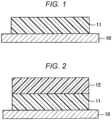
- a first coating film layer 11 can be obtained by applying the coating material of the present invention to an object 10 to be coated.
- coating method of the coating material of the present invention general methods such as brush coating, spray coating, and various coater coating can be used. Coating is usually performed 1 and 2 times.
- the thickness of the first coating film layer 11 is not particularly limited, but is preferably 1000 ⁇ m or less, because the oil component can easily permeate to the surface of the coating film layer, in other words, the oil permeability with respect to the first coating film layer 11 is obtained, and is preferably 50 ⁇ m or more from the viewpoint of strength.
- Examples of the object 10 to be coated used in the present invention include polyurethane resins, polyurethane acrylic resins, rubber-based resins, vinyl chloride resins, polyester resins, silicone resins, elastomers, fluorine resins, polyamide resins, polyolefin resins (polyethylene, polypropylene, etc.), metal plates or metal foils (aluminum, copper, silver, iron, nickel, tin, stainless steel, etc.), concrete, ceramics, etc.
- the coating material can be cured or dried by being left to stand in an environment of, for example, -20°C to 80°C, preferably 0 to 40°C for, for example, 8 hours to 300 hours, preferably 24 hours to 200 hours.
- the following formula (1) Gel fraction % of post-decompression coating film layer-gel fraction % of initial coating film layer ⁇ 0.5 % (In the formula (1), the gel fraction (%) of the initial coating film layer is a value obtained by the following formula (2), and the gel fraction (%) of the post-decompression coating film layer is a value determined by the following formula (3)).
- Gel fraction % of initial coating film layer mass g of initial coating film layer after heating and drying / mass g of initial coating film layer ⁇ 100 (In the formula (2), the initial coating film layer is a coating film layer obtained by curing the coating material, and the initial coating film layer after heating and drying is a coating film layer obtained by immersing the coating film layer in toluene for 24 hours and heating and drying the coating film layer in an environment of 150°C for 2 hours).
- the post-decompression coating film layer is a coating film layer obtained by drying the coating film layer obtained by curing the coating material under a reduced pressure of -0.1 MPa in an environment of 40°C for 16 hours
- the post-decompression coating film layer after heating and drying is a coating film layer obtained by immersing the post-decompression coating film layer in toluene for 24 hours, and heating and drying the post-decompression coating film layer in an environment of 150°C for 2 hours).
- the left side of the formula (1) may be referred to as a "difference in post-decompression gel fraction".
- the first oil component gradually volatilizes, and a decrease in the concentration of the second oil component in the coating film layer can be prevented when the coating material of the present invention is cured to be used as the coating film layer.
- the coating material of the present invention is cured to be used as the coating film layer.
- the difference in post-decompression gel fraction is more preferably 1% or more, even more preferably 1.5% or more, and particularly preferably 2% or more, from the viewpoint of preventing a decrease in bleeding temperature.
- the gel fraction of the post-decompression coating film layer is preferably from 15% to 85%, more preferably from 20% to 80%, still more preferably from 25% to 75%.
- the gel fraction of the initial coating film layer is preferably 15% to 85%, more preferably 20% to 80%, and still more preferably 25% to 75%.
- a second coating film layer 12 can be formed on the coating film layer 11 obtained from the coating material of the present invention with a top-coat coating material as necessary.
- the top-coat coating material is not particularly limited, and for example, the same coating material as the coating material of the present invention can be used, but the top-coat coating material may not contain an oil component.
- top-coat coating material As a coating method of the top-coat coating material, general methods such as brush coating, spray coating, and various coater coating can be used. Coating is usually performed 1 and 2 times.
- the thickness of the second coating film layer 12 is not particularly limited, but is preferably 500 ⁇ m or less, because the oil component can easily permeate to the surface of the coating film layer, in other words, the oil permeability with respect to the second coating film layer 12 is obtained, and is preferably 50 ⁇ m or more from the viewpoint of strength.
- the curing or drying temperature and the curing or drying time at the time of coating the first coating film layer 11 with the top-coat coating material are the same as the curing or drying temperature and the curing or drying time at the time of coating the object 10 to be coated with the coating material of the present invention.
- the curing or drying of the coating material of the present invention and the curing or drying of the top-coat coating material may be performed simultaneously or separately.
- a coating film layer of the present invention is obtained by curing or drying the coating material of the present invention.
- a laminate of the present invention contains the coating film layer of the present invention and a pressure-sensitive adhesive layer.
- the laminate of the present invention is obtained by curing or drying the coating material of the present invention in advance in a state where a thin film having a thickness of, for example, 10 ⁇ m to 1000 ⁇ m is formed to form a coating film layer, and providing a pressure-sensitive adhesive layer on the coating film layer by using a known process of related art.
- the pressure-sensitive adhesive layer can be used to cause a coating film layer obtained by curing or drying the coating material of the present invention to adhere to the surface of various objects.
- the pressure-sensitive adhesive layer is not particularly limited, and examples thereof include an acrylic resin-based pressure-sensitive adhesive, an epoxy resin-based pressure-sensitive adhesive, an amino resin-based pressure-sensitive adhesive, a vinyl resin-based (such as a vinyl acetate-based polymer) pressure-sensitive adhesive, a curable acrylic resin-based pressure-sensitive adhesive, and a silicone resin-based pressure-sensitive adhesive, etc.
- the pressure-sensitive adhesive layer may be an oil-impermeable pressure-sensitive adhesive layer in order to prevent the oil component from flowing out of the coating film layer.
- the oil-impermeable pressure-sensitive adhesive layer is not particularly limited, and examples thereof include an acrylic resin-based pressure-sensitive adhesive, an epoxy resin-based pressure-sensitive adhesive, an amino resin-based pressure-sensitive adhesive, a vinyl resin-based (such as a vinyl acetate-based polymer) pressure-sensitive adhesive, a curable acrylic resin-based pressure-sensitive adhesive, and a silicone resin-based pressure-sensitive adhesive, etc.
- a resin component As a coating material component, a resin component: X-21-5849 (manufactured by Shin-Etsu Chemical Co., Ltd.), a first oil component: dimethyl siloxane oil (manufactured by Shin-Etsu Chemical Co., Ltd., product number: KF-96 (50cs)), a second oil component: phenyl oil (manufactured by Momentive Performance Co., Ltd., product number: TSF-437), an oil component P: dimethyl siloxane oil (manufactured by Shin-Etsu Chemical Co., Ltd., product number: KF-96 (2cs)), silica (manufactured by Nippon Aerosil Co., Ltd., product number: R976), a crosslinking agent (manufactured by Colcoat Co., Ltd., product number: ethylsilicate 40), and a curing catalyst (manufactured by Nippon Chemical Industry Co., Ltd.,
- the resin component (37 parts by mass), the first oil component (5.9 parts by mass), the second oil component (40.7 parts by mass), the oil component P (8.9 parts by mass), and silica (2.2 parts by mass) were mixed under a condition of 25°C and 101 kPa.
- the obtained mixed solution was stirred with a spatula at a speed of about 120 rpm for 60 seconds, and then stirred with a disper (manufactured by Primix Corporation, LABOLUTION) at a speed of 5000 rpm for 10 minutes.
- the crosslinking agent (3.3 parts by mass) and the curing catalyst (2.0 parts by mass) were added to the mixture, and the mixture was stirred with a spatula at a speed of about 120 rpm for 60 seconds to obtain a coating material.
- the obtained coating material was applied to a polyethylene terephthalate (PET) film (Lumirror (registered trademark) 75-S10, manufactured by Toray Industries, Inc.), and cured in an environment of 25°C for one week to form an initial coating film layer.
- PET polyethylene terephthalate
- the initial coating film layer was placed in a decompressing type dryer (DP-43, manufactured by Yamato Scientific Co., Ltd.), and the pressure was reduced to -0.1 MPa by a vacuum pump in an environment of 40°C. The pressure was continuously reduced by the vacuum pump for 30 minutes, and then the initial coating film layer was dried under a reduced pressure of -0.1 MPa for 16 hours in an environment of 40°C in a state where the pump was stopped, thereby obtaining a post-decompression coating film layer.
- DP-43 decompressing type dryer
- An initial coating film layer and a post-decompression coating film layer were formed in the same manner as in Example 1-1 except that 4.45 parts by mass of dimethylsiloxane oil (manufactured by Shin-Etsu Chemical Co., Ltd., product number: KF-96 (2cs)) and 4.45 parts by mass of dimethylsiloxane oil (manufactured by Shin-Etsu Chemical Co., Ltd., product number: KF-96 (5cs)) were used as the oil component P.
- An initial coating film layer and a post-decompression coating film layer were formed in the same manner as in Example 1-1 except that 8.9 parts by mass of dimethylsiloxane oil (manufactured by Shin-Etsu Chemical Co., Ltd., product number: KF-96 (5cs)) was used as the oil component P.
- An initial coating film layer and a post-decompression coating film layer were formed in the same manner as in Example 1-1 except that 14.8 parts by mass of dimethylsiloxane oil (manufactured by Shin-Etsu Chemical Co., Ltd., product number: KF-96 (50cs)) as a first oil component was used without using the oil component P.
- dimethylsiloxane oil manufactured by Shin-Etsu Chemical Co., Ltd., product number: KF-96 (50cs)
- the mass reduction rate of each oil component was measured by the following method. The results are shown below.
- a 6 mL vial bottle (inner diameter of mouth ⁇ body diameter ⁇ total length: 10 mm ⁇ 18 mm ⁇ 40 mm) was prepared, and a mass (mass a) thereof was measured.
- Oil was placed in the vial bottle, and a mass (mass b) of the vial bottle containing the oil was measured.
- the vial bottle containing the oil was left to stand in an environment of 25°C and - 0.1 MPa for 5 hours by a vacuum dryer (DP-43, manufactured by Yamato Scientific Co., Ltd.).
- a mass (mass d) of the vial bottle containing the oil after being left to stand for 5 hours was measured.
- Mass reduction rate mass % mass b ⁇ mass d / mass c ⁇ 100
- a solubility parameter (Hansen solubility parameter) of each molecular unit was determined by calculating a weighted average in terms of molar ratio.
- the Hansen solubility parameter of each molecular unit can be determined by a molecular group contribution method using software "HSPiP, Hansen Solubility Parameters in Practice ver4" available from a link (https://hansen-soLubiLity.com/). Specifically, HSP values ( ⁇ d , ⁇ p , ⁇ h ) of the respective units can be calculated by inputting the respective constituent units in a target substance by a SMILES notation.
- a solubility parameter contribution value A of each component was determined in accordance with the above formula (10). The results are shown below.
- Solubility parameter contribution value A 0
- Solubility parameter contribution value A 3.8
- Oil component P (KF-96 (2cs))
- Solubility parameter contribution value A 0
- Oil component P (KF-96 (5cs))
- Solubility parameter contribution value A 0
- the initial coating film layer was cut into a size of 3.0 cm ⁇ 3.0 cm, and a mass (g) of the initial coating film layer was measured.
- the cut initial coating film layer was placed in a vial bottle filled with 20 g of toluene and immersed in toluene at 20°C for 24 hours. Thereafter, the initial coating film layer was taken out of the vial bottle, dried by heating in an environment of 150°C for 2 hours in a blow dryer, and a mass (g) of the initial coating film layer after heating and drying was measured.
- the gel fraction of the initial coating film layer was determined by the following formula (2).
- Gel fraction % of initial coating film layer mass g of initial coating film layer after heating and drying / mass g of initial coating film layer ⁇ 100
- the post-decompression coating film layer was cut into a size of 3.0 cm ⁇ 3.0 cm, and a mass (g) of the post-decompression coating film layer was measured.
- the cut post-decompression coating film layer was placed in a vial bottle filled with 20 g of toluene and immersed in toluene at 20°C for 24 hours. Thereafter, the post-decompression coating film layer was taken out of the vial bottle, dried by heating in an environment of 150°C for 2 hours in a blow dryer, and a mass (g) of the post-decompression coating film layer after heating and drying was measured.
- the gel fraction of the post-decompression coating film layer was determined by the following formula (3).
- Gel fraction % of post-decompression coating film layer mass g of post- decompression coating film layer after heating and drying / mass g of post-decompression coating film layer ⁇ 100
- a value of the gel fraction (%) of the post-decompression coating film layer - the gel fraction (%) of the initial coating film layer was determined.
- a force required for moving ice blocks adhering on the initial coating film layer in an environment of -20°C was measured.
- the magnitude of this force is defined as an "ice adhesion strength" in the present specification.
- the ice adhesion strength was measured by the following method.
- a cylindrical ice block was produced.
- the ice block was produced by placing a stainless ring (inner diameter: 25 mm) on the bottom surface of a styrol square case 16 type (manufactured by AS ONE Corporation), pouring 6 g of pure water into the stainless ring, freezing the pure water at -20°C for 16 hours or more, and removing the stainless ring after freezing.
- a PET film and the initial coating film layer which are left to stand in an environment of -20°C for 16 hours, were attached to a stainless plate placed in parallel to the floor surface so that the initial coating film layer was on the surface.
- the cylindrical ice block having an adhesion area of 4.9 cm 2 was adhered thereto.
- the ice block was pressed from a direction parallel to the floor surface in an environment of -20°C with a load cell (DPU-50 manufactured by Imada Co., Ltd., attachment jig A type A-4) at a speed of 0.1 mm/sec, and a load applied for 40 seconds was measured with a force gauge (ZTS-50N manufactured by Imada Co., Ltd.). A value obtained by dividing the measured maximum load by the adhesion area of 4.9 cm 2 was recorded as the ice adhesion strength. The test was performed three times, and the average value thereof was determined.
- a load cell DPU-50 manufactured by Imada Co., Ltd., attachment jig A type A-4
- ZTS-50N manufactured by Imada Co., Ltd.
- the initial coating film layer was placed on a Peltier device (VPE-35, manufactured by Bips Corporation). The sample was cooled by 1°C from 5°C to -15°C under N 2 purge (2 L/min) (retention time: 3 minutes), and the temperature at which oil began to bleed out from the surface of the initial coating film layer was confirmed. Bleeding of the oil was observed with a microscope.
- the oil that bleeds out on the surface of the initial coating film layer was collected in an environment of -10°C with a cell scraper (CSS-10, manufactured by Kernian Co., Ltd.), and the oil was absorbed until a change in the mass (oil absorption amount) of oil-absorbing paper was not observed.
- the oil collection by the cell scraper and the absorption by the oil-absorbing paper were repeated seven times per minute.
- the obtained coating film layer was placed in a decompressing type dryer (DP-43, manufactured by Yamato Scientific Co., Ltd.), and the pressure was reduced to -0.1 MPa by a vacuum pump in an environment of 40°C.
- DP-43 decompressing type dryer
- Example 1-1 the pressure was continuously reduced by a vacuum pump for 30 minutes, and then the initial coating film layer was dried under a reduced pressure of -0.1 MPa for 6 hours in an environment of 40°C in a state where the pump was stopped, thereby obtaining a coating film layer after the durability test.
- Example 1-2 the pressure was continuously reduced by a vacuum pump for 30 minutes, and then the initial coating film layer was dried under a reduced pressure of -0.1 MPa for 10 hours in an environment of 40°C in a state where the pump was stopped, thereby obtaining a coating film layer after the durability test.
- Example 1-3 and Comparative Example 1-1 the pressure was continuously reduced by a vacuum pump for 30 minutes, and then the initial coating film layer was dried under a reduced pressure of -0.1 MPa for 16 hours in an environment of 40°C in a state where the pump was stopped, thereby obtaining a coating film layer after the durability test.
- the temperature at which oil starts to bleed out from the surface of the coating film layer was confirmed in the same manner as (in the case of bleeding temperature of initial coating film layer), except that the coating film layer after the durability test described above was used instead of the initial coating film layer.
- the temperature at which oil starts to bleed out from the surface of the coating film layer was confirmed in the same manner as (in the case of bleeding temperature of initial coating film layer), except that the coating film layer after the durability test described above was used instead of the initial coating film layer.
- Examples 1-1 it was confirmed in Examples 1-1, that the same bleeding temperature as that of the initial coating film layer could be maintained even in the coating film layer after the durability test corresponding to 6 months later, in Examples 1-2, the same bleeding temperature as that of the initial coating film layer could be maintained even in the coating film layer after the durability test corresponding to 10 months later, and in Examples 1-3, the same bleeding temperature as that of the initial coating film layer could be maintained even in the coating film layer after the durability test corresponding to 16 months later.
- a resin component As a coating material, a resin component, a first oil component, a second oil component: carbinol oil (manufactured by Shin-Etsu Chemical Co., Ltd., product number: KF-6002), an oil component P: cyclopentasiloxane (manufactured by Shin-Etsu Chemical Co., Ltd., product number: KF-995), silica, a crosslinking agent, and a curing catalyst (manufactured by Tokyo Chemical Industry Co., Ltd., product name: Dibutyltin Dilaurate) were prepared.
- the resin component, the first oil component, the silica, and the crosslinking agent used were the same as those used in Example 1-1.
- the resin component (38.0 parts by mass), the first oil component (26.0 parts by mass), the second oil component (31.0 parts by mass), and silica (2.3 parts by mass) were mixed under a condition of 25°C and 101 kPa.
- the obtained mixed solution was stirred with a spatula at a speed of about 120 rpm for 60 seconds, and then stirred with a disper (manufactured by Primix Corporation, LABOLUTION) at a speed of 5000 rpm for 10 minutes.
- the oil component P (5.0 parts by mass), the crosslinking agent (1.7 parts by mass), and the curing catalyst (1.0 part by mass) were added to the mixed liquid, and the mixture was stirred with a spatula at a speed of about 120 rpm for 60 seconds to obtain a coating material.
- the obtained coating material was applied to a polyethylene terephthalate (PET) film (Lumirror (registered trademark) 75-S10, manufactured by Toray Industries, Inc.), and cured in an environment of 25°C for one week to form a coating film layer (25°C).
- PET polyethylene terephthalate
- a coating film layer (0°C) was formed in accordance with the method described above, except that the content of the first oil component and the content of the second oil component were set as shown in Table 3, and the temperature at which the coating material was cured was set to 0°C.
- a coating film layer (25°C) and a coating film layer (0°C) were formed in the same manner as in Example 2-1 except that the type of the oil component P, the content of the oil component P, the content of the first oil component, and the content of the second oil component were set as shown in Table 3.
- KF-96 (1.5cs) means methylsiloxane oil (manufactured by Shin-Etsu Chemical Co., Ltd., product number: KF-96 (1.5cs))
- KF-96 (2cs) means methylsiloxane oil (manufactured by Shin-Etsu Chemical Co., Ltd., product number: KF-96 (2cs)).
- SP value difference ⁇ The SP value of each component and a difference (SP value difference ⁇ ) between the SP value of the resin component and the SP value of the oil component P were determined in the same manner as in Test Example 1. The results are shown below.
- the solubility parameter contribution value A of each oil component P was determined by the above formula (10). The results are shown below.
- Solubility parameter contribution value A 0
- Solubility parameter contribution value A 5.5
- Oil component P (KF-995), KF-96 (1.5cs), KF-96 (2cs)
- Solubility parameter contribution value A 0
- the obtained coating film layer (25°C) and coating film layer (0° C) were evaluated as follows. The results are shown in Table 4.
- a solubility parameter (Hansen solubility parameter) of each molecular unit was determined by calculating a weighted average in terms of molar ratio.
- the Hansen solubility parameter of each molecular unit can be determined by a molecular group contribution method using software "HSPiP, Hansen Solubility Parameters in Practice ver4" available from a link (https://hansen-soLubiLity.com/). Specifically, HSP values ( ⁇ d , ⁇ p , ⁇ h ) of the respective units can be calculated by inputting the respective constituent units in a target substance by a SMILES notation.
- SP value difference ⁇ a difference between the SP value of each coating film layer and the SP value of the oil component P was determined.
- the SP value of the coating film layer (25°C) and the SP value of the coating film layer (0°C) were the same.
- the bleed oil amount ( ⁇ g/cm 2 ) of the coating film layer (25°C) and the coating film layer (0°C) during the curing period (one week) was measured.
- a represents the bleed oil amount in the coating film layer (25°C)
- b represents the bleed oil amount in the coating film layer (0°C).
- the content of the first oil component and the content of the second oil component are different between the coating film layer (25°C) and the coating film layer (0°C). This is because the curing rate was different between the curing at 25°C and the curing at 0°C, and in the same curing period (one week), the bleeding initiation temperatures of the coating film layer (25°C) and the coating film layer (0°C) were not the same, and the content of the first oil component and the content of the second oil component were adjusted so that the bleeding initiation temperatures of both the coating film layer (25°C) and the coating film layer (0°C) were 0°C.
- Example 2-1 26.0 31.0 20.0 37.0 KF-995 33.2 30.84 370 11.8 0 5.0 0
- Example 2-2 26.0 31.0 20.0 37.0 10.0
- Example 2-3 26.0 31.0 20.0 37.0 20.0
- Example 2-4 26.0 31.0 20.0 37.0 30.0
- Example 2-5 26.0 31.0 20.0 37.0 KF-96 (1.5cs) 130 100.03 311 11.8 0 10.0 0
- Example 2-1 11.9 11.8 0.1 2320 1570 32
- Example 2-2 2382 2286 4 Example 2-3 2420 2370 2
- Example 2-4 2450 2390 2
- Example 2-5 11.8 0.1 2386 2176 9
- Example 2-6 11.8 0.1 2389 876 63 Comparative Example 2-1 - - 2390 773 68
Landscapes
- Chemical & Material Sciences (AREA)
- Organic Chemistry (AREA)
- Life Sciences & Earth Sciences (AREA)
- Engineering & Computer Science (AREA)
- Materials Engineering (AREA)
- Wood Science & Technology (AREA)
- Chemical Kinetics & Catalysis (AREA)
- Paints Or Removers (AREA)
Applications Claiming Priority (3)
| Application Number | Priority Date | Filing Date | Title |
|---|---|---|---|
| JP2020058774 | 2020-03-27 | ||
| JP2020213811 | 2020-12-23 | ||
| PCT/JP2021/010950 WO2021193313A1 (ja) | 2020-03-27 | 2021-03-17 | 塗料、塗膜層及び積層体 |
Publications (2)
| Publication Number | Publication Date |
|---|---|
| EP4130176A1 true EP4130176A1 (de) | 2023-02-08 |
| EP4130176A4 EP4130176A4 (de) | 2024-04-17 |
Family
ID=77892130
Family Applications (1)
| Application Number | Title | Priority Date | Filing Date |
|---|---|---|---|
| EP21776425.7A Withdrawn EP4130176A4 (de) | 2020-03-27 | 2021-03-17 | Beschichtung, beschichtungsfilmschicht und laminat |
Country Status (5)
| Country | Link |
|---|---|
| US (1) | US20230109348A1 (de) |
| EP (1) | EP4130176A4 (de) |
| JP (1) | JPWO2021193313A1 (de) |
| CN (1) | CN115362227B (de) |
| WO (1) | WO2021193313A1 (de) |
Families Citing this family (2)
| Publication number | Priority date | Publication date | Assignee | Title |
|---|---|---|---|---|
| EP4147870A4 (de) * | 2020-05-08 | 2024-06-12 | Nitto Denko Corporation | Beschichtungsmaterial und laminat |
| WO2022202721A1 (ja) * | 2021-03-26 | 2022-09-29 | 日東電工株式会社 | 塗料 |
Family Cites Families (10)
| Publication number | Priority date | Publication date | Assignee | Title |
|---|---|---|---|---|
| GB8708876D0 (en) * | 1987-04-14 | 1987-08-05 | Qmc Ind Res | Ice release surfaces |
| JP3781900B2 (ja) | 1998-07-15 | 2006-05-31 | エヌ・ティ・ティ・アドバンステクノロジ株式会社 | 撥水性塗膜 |
| JP4867138B2 (ja) * | 2004-06-04 | 2012-02-01 | ダイキン工業株式会社 | 溶剤型塗料組成物 |
| JP4798396B2 (ja) * | 2008-07-07 | 2011-10-19 | 信越化学工業株式会社 | 水中生物付着防止塗料組成物及びそれを用いた水中構造物 |
| EP2940089A4 (de) * | 2012-12-27 | 2016-08-03 | Asahi Glass Co Ltd | Rückseitenbeschichtungszusammensetzung und spiegel damit |
| US9688894B2 (en) * | 2013-01-30 | 2017-06-27 | University of Pittsburgh—of the Commonwealth System of Higher Education | Compositions for prevention of ice build-up |
| KR20180020964A (ko) * | 2015-04-27 | 2018-02-28 | 더 리젠츠 오브 더 유니버시티 오브 미시건 | 내구성 아이스포빅 표면 |
| CN110475833A (zh) * | 2017-03-31 | 2019-11-19 | 日东电工株式会社 | 涂膜形成用组合物、涂膜及粘合片 |
| EP3637430B1 (de) | 2018-10-10 | 2023-11-15 | Tata Consultancy Services Limited | Unauffällige überwachung physiologischer signale in echtzeit |
| WO2020096071A1 (ja) * | 2018-11-09 | 2020-05-14 | 日東電工株式会社 | 塗料およびフィルム |
-
2021
- 2021-03-17 EP EP21776425.7A patent/EP4130176A4/de not_active Withdrawn
- 2021-03-17 JP JP2022510016A patent/JPWO2021193313A1/ja not_active Ceased
- 2021-03-17 US US17/914,754 patent/US20230109348A1/en not_active Abandoned
- 2021-03-17 WO PCT/JP2021/010950 patent/WO2021193313A1/ja not_active Ceased
- 2021-03-17 CN CN202180024564.7A patent/CN115362227B/zh not_active Expired - Fee Related
Also Published As
| Publication number | Publication date |
|---|---|
| CN115362227B (zh) | 2024-01-26 |
| US20230109348A1 (en) | 2023-04-06 |
| JPWO2021193313A1 (de) | 2021-09-30 |
| WO2021193313A1 (ja) | 2021-09-30 |
| CN115362227A (zh) | 2022-11-18 |
| EP4130176A4 (de) | 2024-04-17 |
Similar Documents
| Publication | Publication Date | Title |
|---|---|---|
| EP3878650A1 (de) | Folienkörper | |
| EP3878916A1 (de) | Beschichtungsmaterial und folie | |
| EP4129665B1 (de) | Folienkörper | |
| US20230109348A1 (en) | Coating material, coating film layer, and laminate | |
| EP4148092A1 (de) | Beschichtungsmaterial und laminat | |
| EP4147870A1 (de) | Beschichtungsmaterial und laminat | |
| WO2021193973A1 (ja) | 塗料及び積層体 | |
| EP4317336A1 (de) | Beschichtungsmaterial | |
| WO2023190417A1 (ja) | シート体 | |
| TW202016193A (zh) | 含有操作材料之三維晶格結構,包含該三維晶格結構之組成物,以及用於製造該三維晶格結構之組成物及方法 | |
| Wonnie Ma et al. | Evaluation of natural oil polyol hydrophobic acrylic-based coating incorporated with SiO2 nanoparticles for enhanced corrosion protection | |
| Kahlmeyer et al. | Microencapsulated markers for damage detection in adhesive joints | |
| US20240166931A1 (en) | Sheet body | |
| WO2023190795A1 (ja) | 塗膜層 | |
| JP2024130929A (ja) | ブリード塗膜の製造方法、及び塗膜のブリード機能を付与又は回復させる方法 | |
| JP2025155971A (ja) | シート体 |
Legal Events
| Date | Code | Title | Description |
|---|---|---|---|
| STAA | Information on the status of an ep patent application or granted ep patent |
Free format text: STATUS: THE INTERNATIONAL PUBLICATION HAS BEEN MADE |
|
| PUAI | Public reference made under article 153(3) epc to a published international application that has entered the european phase |
Free format text: ORIGINAL CODE: 0009012 |
|
| STAA | Information on the status of an ep patent application or granted ep patent |
Free format text: STATUS: REQUEST FOR EXAMINATION WAS MADE |
|
| 17P | Request for examination filed |
Effective date: 20220912 |
|
| AK | Designated contracting states |
Kind code of ref document: A1 Designated state(s): AL AT BE BG CH CY CZ DE DK EE ES FI FR GB GR HR HU IE IS IT LI LT LU LV MC MK MT NL NO PL PT RO RS SE SI SK SM TR |
|
| DAV | Request for validation of the european patent (deleted) | ||
| DAX | Request for extension of the european patent (deleted) | ||
| A4 | Supplementary search report drawn up and despatched |
Effective date: 20240315 |
|
| RIC1 | Information provided on ipc code assigned before grant |
Ipc: C09J 7/20 20180101ALI20240312BHEP Ipc: C09D 183/04 20060101ALI20240312BHEP Ipc: C09D 5/16 20060101ALI20240312BHEP Ipc: C08G 77/16 20060101ALI20240312BHEP Ipc: C09J 7/38 20180101ALI20240312BHEP Ipc: C09D 7/63 20180101ALI20240312BHEP Ipc: C09K 3/18 20060101ALI20240312BHEP Ipc: C09D 201/00 20060101AFI20240312BHEP |
|
| STAA | Information on the status of an ep patent application or granted ep patent |
Free format text: STATUS: THE APPLICATION IS DEEMED TO BE WITHDRAWN |
|
| 18D | Application deemed to be withdrawn |
Effective date: 20241005 |