EP4130355A1 - Fibre et procédé de fabrication de fibre - Google Patents
Fibre et procédé de fabrication de fibre Download PDFInfo
- Publication number
- EP4130355A1 EP4130355A1 EP21776060.2A EP21776060A EP4130355A1 EP 4130355 A1 EP4130355 A1 EP 4130355A1 EP 21776060 A EP21776060 A EP 21776060A EP 4130355 A1 EP4130355 A1 EP 4130355A1
- Authority
- EP
- European Patent Office
- Prior art keywords
- mass
- fiber
- raw material
- temperature
- igcc
- Prior art date
- Legal status (The legal status is an assumption and is not a legal conclusion. Google has not performed a legal analysis and makes no representation as to the accuracy of the status listed.)
- Pending
Links
Images


Classifications
-
- C—CHEMISTRY; METALLURGY
- C03—GLASS; MINERAL OR SLAG WOOL
- C03B—MANUFACTURE, SHAPING, OR SUPPLEMENTARY PROCESSES
- C03B37/00—Manufacture or treatment of flakes, fibres, or filaments from softened glass, minerals, or slags
- C03B37/01—Manufacture of glass fibres or filaments
- C03B37/02—Manufacture of glass fibres or filaments by drawing or extruding, e.g. direct drawing of molten glass from nozzles; Cooling fins therefor
-
- D—TEXTILES; PAPER
- D01—NATURAL OR MAN-MADE THREADS OR FIBRES; SPINNING
- D01F—CHEMICAL FEATURES IN THE MANUFACTURE OF ARTIFICIAL FILAMENTS, THREADS, FIBRES, BRISTLES OR RIBBONS; APPARATUS SPECIALLY ADAPTED FOR THE MANUFACTURE OF CARBON FILAMENTS
- D01F9/00—Artificial filaments or the like of other substances; Manufacture thereof; Apparatus specially adapted for the manufacture of carbon filaments
- D01F9/08—Artificial filaments or the like of other substances; Manufacture thereof; Apparatus specially adapted for the manufacture of carbon filaments of inorganic material
-
- C—CHEMISTRY; METALLURGY
- C03—GLASS; MINERAL OR SLAG WOOL
- C03B—MANUFACTURE, SHAPING, OR SUPPLEMENTARY PROCESSES
- C03B37/00—Manufacture or treatment of flakes, fibres, or filaments from softened glass, minerals, or slags
- C03B37/01—Manufacture of glass fibres or filaments
-
- C—CHEMISTRY; METALLURGY
- C03—GLASS; MINERAL OR SLAG WOOL
- C03B—MANUFACTURE, SHAPING, OR SUPPLEMENTARY PROCESSES
- C03B37/00—Manufacture or treatment of flakes, fibres, or filaments from softened glass, minerals, or slags
- C03B37/075—Manufacture of non-optical fibres or filaments consisting of different sorts of glass or characterised by shape, e.g. undulated fibres
-
- C—CHEMISTRY; METALLURGY
- C03—GLASS; MINERAL OR SLAG WOOL
- C03B—MANUFACTURE, SHAPING, OR SUPPLEMENTARY PROCESSES
- C03B5/00—Melting in furnaces; Furnaces so far as specially adapted for glass manufacture
- C03B5/005—Melting in furnaces; Furnaces so far as specially adapted for glass manufacture of glass-forming waste materials
-
- C—CHEMISTRY; METALLURGY
- C03—GLASS; MINERAL OR SLAG WOOL
- C03C—CHEMICAL COMPOSITION OF GLASSES, GLAZES OR VITREOUS ENAMELS; SURFACE TREATMENT OF GLASS; SURFACE TREATMENT OF FIBRES OR FILAMENTS MADE FROM GLASS, MINERALS OR SLAGS; JOINING GLASS TO GLASS OR OTHER MATERIALS
- C03C1/00—Ingredients generally applicable to manufacture of glasses, glazes, or vitreous enamels
- C03C1/002—Use of waste materials, e.g. slags
-
- C—CHEMISTRY; METALLURGY
- C03—GLASS; MINERAL OR SLAG WOOL
- C03C—CHEMICAL COMPOSITION OF GLASSES, GLAZES OR VITREOUS ENAMELS; SURFACE TREATMENT OF GLASS; SURFACE TREATMENT OF FIBRES OR FILAMENTS MADE FROM GLASS, MINERALS OR SLAGS; JOINING GLASS TO GLASS OR OTHER MATERIALS
- C03C13/00—Fibre or filament compositions
- C03C13/06—Mineral fibres, e.g. slag wool, mineral wool, rock wool
-
- C—CHEMISTRY; METALLURGY
- C03—GLASS; MINERAL OR SLAG WOOL
- C03C—CHEMICAL COMPOSITION OF GLASSES, GLAZES OR VITREOUS ENAMELS; SURFACE TREATMENT OF GLASS; SURFACE TREATMENT OF FIBRES OR FILAMENTS MADE FROM GLASS, MINERALS OR SLAGS; JOINING GLASS TO GLASS OR OTHER MATERIALS
- C03C3/00—Glass compositions
- C03C3/04—Glass compositions containing silica
- C03C3/062—Glass compositions containing silica with less than 40% silica by weight
-
- C—CHEMISTRY; METALLURGY
- C03—GLASS; MINERAL OR SLAG WOOL
- C03C—CHEMICAL COMPOSITION OF GLASSES, GLAZES OR VITREOUS ENAMELS; SURFACE TREATMENT OF GLASS; SURFACE TREATMENT OF FIBRES OR FILAMENTS MADE FROM GLASS, MINERALS OR SLAGS; JOINING GLASS TO GLASS OR OTHER MATERIALS
- C03C3/00—Glass compositions
- C03C3/04—Glass compositions containing silica
- C03C3/076—Glass compositions containing silica with 40% to 90% silica, by weight
- C03C3/083—Glass compositions containing silica with 40% to 90% silica, by weight containing aluminium oxide or an iron compound
- C03C3/085—Glass compositions containing silica with 40% to 90% silica, by weight containing aluminium oxide or an iron compound containing an oxide of a divalent metal
- C03C3/087—Glass compositions containing silica with 40% to 90% silica, by weight containing aluminium oxide or an iron compound containing an oxide of a divalent metal containing calcium oxide, e.g. common sheet or container glass
-
- C—CHEMISTRY; METALLURGY
- C03—GLASS; MINERAL OR SLAG WOOL
- C03B—MANUFACTURE, SHAPING, OR SUPPLEMENTARY PROCESSES
- C03B2203/00—Fibre product details, e.g. structure, shape
- C03B2203/02—External structure or shape details
-
- Y—GENERAL TAGGING OF NEW TECHNOLOGICAL DEVELOPMENTS; GENERAL TAGGING OF CROSS-SECTIONAL TECHNOLOGIES SPANNING OVER SEVERAL SECTIONS OF THE IPC; TECHNICAL SUBJECTS COVERED BY FORMER USPC CROSS-REFERENCE ART COLLECTIONS [XRACs] AND DIGESTS
- Y02—TECHNOLOGIES OR APPLICATIONS FOR MITIGATION OR ADAPTATION AGAINST CLIMATE CHANGE
- Y02E—REDUCTION OF GREENHOUSE GAS [GHG] EMISSIONS, RELATED TO ENERGY GENERATION, TRANSMISSION OR DISTRIBUTION
- Y02E20/00—Combustion technologies with mitigation potential
- Y02E20/16—Combined cycle power plant [CCPP], or combined cycle gas turbine [CCGT]
- Y02E20/18—Integrated gasification combined cycle [IGCC], e.g. combined with carbon capture and storage [CCS]
-
- Y—GENERAL TAGGING OF NEW TECHNOLOGICAL DEVELOPMENTS; GENERAL TAGGING OF CROSS-SECTIONAL TECHNOLOGIES SPANNING OVER SEVERAL SECTIONS OF THE IPC; TECHNICAL SUBJECTS COVERED BY FORMER USPC CROSS-REFERENCE ART COLLECTIONS [XRACs] AND DIGESTS
- Y02—TECHNOLOGIES OR APPLICATIONS FOR MITIGATION OR ADAPTATION AGAINST CLIMATE CHANGE
- Y02W—CLIMATE CHANGE MITIGATION TECHNOLOGIES RELATED TO WASTEWATER TREATMENT OR WASTE MANAGEMENT
- Y02W30/00—Technologies for solid waste management
- Y02W30/50—Reuse, recycling or recovery technologies
- Y02W30/91—Use of waste materials as fillers for mortars or concrete
Definitions
- the present invention relates to a fiber and a fiber manufacturing method.
- IGCC Integrated coal Gasification Combined Cycle
- IGCC ultra-supercritical pressure coal-fired power generation
- A-USC coal-fired power generation advanced ultra-supercritical pressure coal-fired power generation
- IGCC is expected as a highly efficient next-generation power generation method.
- utilization methods thereof have been established only to the extent that the waste is subjected to processing such as pulverization and is utilized as aggregate for cement (see Patent Document 1), and there is still room for further improvement.
- Patent Document 1 JP 2017-014052 A
- the invention was achieved in view of the above-described problems, and it is an object of the invention to provide a fiber and a fiber manufacturing method, in which a waste material discharged from integrated coal gasification combined cycle can be utilized more effectively.
- a fiber according to the invention includes a waste material discharged from integrated coal gasification combined cycle (IGCC) as a raw material.
- IGCC integrated coal gasification combined cycle
- a fiber and a fiber manufacturing method in which a waste material discharged from integrated coal gasification combined cycle can be utilized more effectively, can be provided.
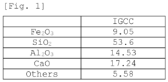
- Fig. 1 is a diagram illustrating a component composition of a raw material (IGCC waste material) according to Example 1;
- a fiber according to the present Embodiment 1 uses a waste material discharged from integrated coal gasification combined cycle (IGCC) (hereinafter, also referred to as IGCC waste material.
- IGCC waste material includes slag, coal ash, and the like discharged from IGCC) as a raw material.
- the IGCC waste material as the raw material contains SiO 2 and Al 2 O 3 as main components, the proportion occupied by Al 2 O 3 in the sum of SiO 2 and Al 2 O 3 is in a specific range, and the IGCC waste material further contains a specific amount of CaO.
- the raw material of the fiber according to the present Embodiment 1 is an IGCC waste material, and the total content of SiO 2 and Al 2 O 3 in the raw material is preferably 40% by mass or more and 70% by mass or less.
- the melting temperature of the raw material becomes high or the viscosity of the molten material becomes high, which results in inferior melt spinnability.
- melt spinning refers to a technique of discharging a molten material obtained by melting a raw material by heat through a hole (through-hole) formed in a spinneret to produce a fibrous form and then cooling and hardening the fibrous form.
- melt spinnability refers to the ease of manufacturing of a fiber by melt spinning.
- the proportion of Al 2 O 3 in the sum of SiO 2 and Al 2 O 3 ([A]/([A] + [S])) (mass ratio) is in the range of 0.15 to 0.40.
- [A]/([A] + [S]) (mass ratio) is either less than 0.15 or more than 0.40, the melt temperature becomes high or the viscosity of the molten material becomes high, which results in inferior melt spinnability.
- the content of CaO is preferably 5% by mass or more and 30% by mass or less.
- the content of CaO is less than 5% by mass, the melting temperature of the fiber becomes high, and therefore, it is not preferable from the viewpoint of energy saving.
- the content of CaO is more preferably 30% by mass or less.
- the fiber according to the present Embodiment 1 when SiO 2 , Al 2 O 3 , and CaO of the components are blended so as to satisfy the above-mentioned composition conditions, the fiber according to the present Embodiment 1 can be obtained without any restriction on the raw materials.
- the raw materials of the fiber according to the present Embodiment 1 it is preferable to use a waste material (IGCC waste material) discharged by integrated coal gasification combined cycle (IGCC), or the like.
- IGCC waste material includes SiO 2 and Al 2 O 3 as main components, the IGCC waste is suitable for obtaining the fiber according to the present Embodiment 1, and the raw material cost can be suppressed.
- the fiber according to the present Embodiment is not precluded from including unavoidable impurities.
- the main examples of unavoidable impurities include MgO, Na 2 O, K 2 O, TiO 2 , and CrO 2 .
- the component ratio of the raw materials there is no substantial difference between the component ratio (mass ratio) of the raw materials and the component ratio (mass ratio) of the fiber manufactured by melting the raw materials. For this reason, the component ratio of the raw materials can be regarded as the component ratio of the fiber manufactured by melting the raw materials.
- the fiber according to the present Embodiment 1 is highly amorphous. For this reason, the fiber has almost no decrease in strength caused by separation at the crystalline phase / non-crystalline phase interface, and a fiber having high strength can be obtained.
- the degree of amorphization which is a measure of amorphousness, is calculated by the following Mathematical Formula (1) based on an X-ray diffraction (XRD) pattern.
- Degree of amorphization % la / la + lc ⁇ 100
- the degree of amorphization of the fiber according to the present Embodiment 1 may vary depending on the composition of the fiber; however, the degree of amorphization usually presents a value of 90% or higher.
- the degree of amorphization of the fiber even reaches as high as 95% or higher in some cases, and in case where the degree of amorphization is the highest, the fiber is substantially composed only of an amorphous phase.
- being substantially composed only of an amorphous phase implies that only the amorphous halo is recognized in the X-ray diffraction pattern, and a peak for a crystalline material was not recognized.
- an IGCC waste material discharged by integrated coal gasification combined cycle was prepared as a raw material (raw material S1) of the fiber.
- raw material S1 a material discharged from a domestic Integrated coal Gasification Combined Cycle was used.
- the raw material S1 was a 100% IGCC waste material.
- Fig. 1 shows the component composition of the raw material S1 (IGCC waste material).
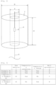
- the electric furnace 1 is a cylindrical body having a height H of 60 cm and an outer diameter D of 50 cm, in which a through-hole 4 having an inner diameter d of 10 cm is formed at the center.
- a Tammann tube 2 having an inner diameter of 2.1 cm and a length of 10 cm is suspended by a suspension rod 3 in the through-hole 4.
- the Tammann tube 2 is charged with 30 g of the raw material (raw material S1).
- a hole having a diameter of 2 mm is provided at the center of the bottom part of the Tammann tube 2, and when the blend is melted by heating, the molten material flows out through the hole provided in the bottom part of the Tammann tube by gravity.
- the molten material that has flowed out is exposed to external air to be cooled and is solidified into a fiber.
- the fiber is substantially only amorphous.
- temperature is raised according to a predetermined temperature raising program, and it has been confirmed in advance that the temperature of the molten material in the Tammann tube 2 follows the temperature profile inside the furnace at a temperature lower by approximately 50 degrees.
- melt spinnability was rated as follows.
- Fig. 3 is a table summarizing the results of the presence or absence of temperature retention (annealing), the presence or absence of temperature change, and melt spinnability for the raw material S1 used in Examples A1 and A2 and Comparative Examples E1 to E3.
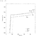
- Fig. 4 is a table showing changes over time in the temperature inside the furnace in Examples A1 and A2 and Comparative Examples E1 to E3.
- Fig. 4(a) is a table showing changes over time in the temperature inside the furnace in Example A1.
- Fig. 4(b) is a table showing changes over time in the temperature inside the furnace in Example A2.
- Fig. 4(c) is a table showing changes over time in the temperature inside the furnace in Comparative Example E1.
- Fig. 4(d) is a table showing changes over time in the temperature inside the furnace in Comparative Example E2.
- Fig. 4(e) is a table showing changes over time in the temperature inside the furnace in Comparative Example E3.
- Fig. 5 is a graph obtained by plotting the changes over time in the temperature inside the furnace in Examples A1 and A2 and Comparative Examples E1 to E3 shown in Fig. 4 .
- the raw material S1 was placed in the Tammann tube. Next, the temperature inside the furnace was raised to 1350 degrees (the temperature of the raw material S1 was 1300 degrees), and then the raw material S1 was maintained at approximately 1350 degrees for a predetermined time (55 minutes) (temperature retention: Yes). Subsequently, spinnability was checked while changing the temperature inside the furnace (temperature change: Yes), and the raw material S1 formed a fiber (melt spinnability: A).
- the raw material S1 was placed in the Tammann tube. Next, the temperature inside the furnace was raised to 1375 degrees (the temperature of the raw material S1 was 1325 degrees), and then the raw material S1 was maintained at approximately 1375 degrees for a predetermined time (120 minutes) (temperature retention: Yes). Subsequently, spinnability was checked while changing the temperature inside the furnace (temperature change: Yes), and the raw material S1 formed a fiber (melt spinnability: A).
- the raw material S1 was placed in the Tammann tube, subsequently the temperature inside the furnace was raised to 1350 degrees (the temperature of the raw material S1 was 1300 degrees), and then the raw material S1 was maintained at approximately 1350 degrees for a predetermined time (94 minutes) (temperature retention: Yes). Subsequently, spinnability was checked without changing the temperature inside the furnace (temperature change: No); however, the raw material S1 did not form a fiber (melt spinnability: C) .
- the raw material S1 was placed in the Tammann tube, subsequently the temperature inside the furnace was raised to 1400 degrees (the temperature of the raw material S1 was 1350 degrees), and then spinnability was checked while changing the temperature inside the furnace (temperature change: Yes). However, the raw material that had been melted and softened came out through the hole provided in the bottom part of the Tammann tube, and very short fibers were generated; however, the raw material S1 did not form a fiber (melt spinnability: B). Furthermore, after the temperature was raised to 1400 degrees, temperature retention of maintaining the temperature for a predetermined time was not carried out (temperature retention: No).
- the raw material S1 was placed in the Tammann tube, subsequently the temperature inside the furnace was raised to 1320 degrees (the temperature of the raw material S1 was 1270 degrees), and then the raw material S1 was maintained at approximately 1320 degrees for a predetermined time (20 minutes) (temperature retention: Yes). Subsequently, it was checked whether the raw material S1 was spun without changing the temperature inside the furnace (temperature change: No); however, the raw material S1 did not form a fiber (melt spinnability: C).
- a fiber can be manufactured by using an IGCC waste material discharged by integrated coal gasification combined cycle (IGCC) as a raw material.
- IGCC integrated coal gasification combined cycle
- Fig. 6 is an XRD pattern of a fiber formed from the raw material S1. As shown in Fig. 6 , only the amorphous halo was recognized in the X-ray diffraction (XRD) pattern of the fiber obtained in the Example A1, and a peak for a crystalline material was not recognized. From this, it was understood that the fiber produced from the IGCC waste material was substantially composed only of an amorphous material.
- XRD X-ray diffraction
- Fig. 7 is an enlarge view (micrograph) of the fiber formed from the raw material S1 shown in Fig. 6 .
- a fiber having an outer diameter of more than 500 ⁇ m could be obtained.
- This fiber is substantially composed only of an amorphous material as described with reference to Fig. 6 . This is speculated to be because, after the IGCC waste material in a molten state has flowed out through the hole provided at the center of the bottom part of the Tammann tube 2, the IGCC waste material is quenched and then becomes amorphous without adopting a regular atomic arrangement.
- a fiber having an outer diameter of more than 500 ⁇ m is substantially composed only of an amorphous material.
- the rate of cooling is faster. Therefore, it is presumed that as the outer diameter is finer than the outer diameter (505.97 ⁇ m) of the fiber shown in Fig. 7 , the fiber is substantially composed only of an amorphous material. More specifically, it is presumed that a fiber having an outer diameter of 500 ⁇ m or less is substantially composed only of an amorphous material.
- a fiber according to the present Embodiment 2 includes a waste material discharged from integrated coal gasification combined cycle (IGCC) as a raw material.
- the fiber according to the present Embodiment 2 includes at least one of basalt and a waste material discharged from a non-IGCC thermal power plant that uses coal as fuel, as a raw material in the waste material discharged from integrated coal gasification combined cycle (IGCC).
- the total content of SiO 2 and Al 2 O 3 in the raw material of the fiber according to the present Embodiment 2 is 40% by mass or more and 70% by mass or less. Furthermore, with regard to the raw material of the fiber according to the present Embodiment 2, it is preferable that the proportion of Al 2 O 3 in the sum of SiO 2 and Al 2 O 3 ([A]/([A] + [S])) (mass ratio) is in the range of 0.15 to 0.40. Furthermore, with regard to the raw material of the fiber according to the present Embodiment 2, it is preferable that the content of CaO is 5% by mass or more and 30% by mass or less. Furthermore, similarly to the fiber according to Embodiment 1, it is preferable that the fiber according to the present Embodiment 2 is substantially composed only of an amorphous phase.
- a mixture obtained by an IGCC waste material, a waste material discharged from a non-IGCC thermal power plant that uses coal as fuel, and basalt at a predetermined mixing ratio (% by mass) was prepared as a raw material of the fiber.
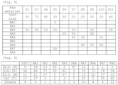
- the respective mixing ratios of raw materials S2 to S11 will be described below with reference to Fig. 8 (since the numbers after the decimal point are rounded off, the sum may not necessarily add up to 100%).
- the IGCC slag indicates an IGCC waste material
- FA1 to FA8 indicate waste materials from coal-fired power plants that are not IGCC (FA1 to FA8 are waste materials discharged from different power plants).
- BA1 indicates basalt (basalt).
- the components of raw materials S2 to S11 were analyzed by an X-ray fluorescence analysis method. Furthermore, the electric furnace described with reference to Fig. 2 was used for manufacturing fibers from the raw materials S2 to S11.
- Raw material S2 was a mixture of an IGCC waste material discharged from an integrated coal gasification combined cycle power plant at a proportion of 50% by mass and a waste material FA2 discharged from a coal-fired power plant at a proportion of 50% by mass.
- Raw material S3 was a mixture of an IGCC waste material discharged from an integrated coal gasification combined cycle power plant at a proportion of 75% by mass and a waste material FA2 discharged from the coal-fired power plant at a proportion of 25% by mass.
- Raw material S4 was a mixture of an IGCC waste material discharged from an integrated coal gasification combined cycle power plant at a proportion of 90% by mass and a waste material FA2 discharged from the coal-fired power plant at a proportion of 10% by mass.
- Raw material S5 was a mixture of an IGCC waste material discharged from an integrated coal gasification combined cycle power plant at a proportion of 30% by mass, basalt at a proportion of 5% by mass, a waste material FA2 discharged from the coal-fired power plant at a proportion of 15% by mass, and a waste material FA7 discharged from a coal-fired power plant at a proportion of 50 by mass.
- Raw material S6 was a mixture of an IGCC waste material discharged from an integrated coal gasification combined cycle power plant at a proportion of 50% by mass and a waste material FA3 discharged from a coal-fired power plant at a proportion of 50% by mass.
- Raw material S7 is a mixture of an IGCC waste material discharged from an integrated coal gasification combined cycle power plant at a proportion of 20% by mass, a waste material FA2 discharged from the coal-fired power plant at a proportion of 10% by mass, a waste material FA3 discharged from the coal-fired power plant at a proportion of 30% by mass, and a waste material FA4 discharged from a coal-fired power plant at a proportion of 40% by mass.
- Raw material S8 is a mixture of an IGCC waste material discharged from an integrated coal gasification combined cycle power plant at a proportion of 25% by mass, a waste material FA4 discharged from the coal-fired power plant at a proportion of 10% by mass, and a waste material FA6 discharged from a coal-fired power plant at a proportion of 65% by mass.
- Raw material S9 is a mixture of an IGCC waste material discharged from an integrated coal gasification combined cycle power plant at a proportion of 10% by mass, a waste material FA2 discharged from the coal-fired power plant at a proportion of 16% by mass, a waste material FA3 discharged from the coal-fired power plant at a proportion of 36% by mass, and a waste material FA6 discharged from the coal-fired power plant at a proportion of 37% by mass.
- Raw material S10 is a mixture of an IGCC waste material discharged from an integrated coal gasification combined cycle power plant at a proportion of 25% by mass, a waste material FA4 discharged from the coal-fired power plant at a proportion of 10% by mass, and a waste material FA6 discharged from the coal-fired power plant at a proportion of 65% by mass.
- Raw material S11 is a mixture of an IGCC waste material discharged from an integrated coal gasification combined cycle power plant at a proportion of 60% by mass and a waste material FA2 discharged from the coal-fired power plant at a proportion of 40% by mass.
- the components of the waste materials constituting the raw materials S2 to S11 and basalt were analyzed by an X-ray fluorescence analysis method.
- the components of the waste materials and the like were analyzed by using an X-ray fluorescence analyzer (Philips PW2404) of Philips Japan, Ltd., while keeping the sample chamber of the X-ray fluorescence analyzer in a vacuum state.
- Fig. 9 shows the component compositions of the waste materials and the like according to Example 2.
- 0% by mass means that the amount is so small that the amount cannot be measured, and this does not strictly mean "zero (0)".
- [F] is 55% by mass
- [S] is 35% by mass
- [A] is 5% by mass
- [C] is 2% by mass
- the content of others is 3% by mass.
- [F] is 2% by mass
- [S] is 62% by mass
- [A] is 27% by mass
- [C] is 3% by mass
- the content of others is 5% by mass.
- [F] is 97% by mass
- [S] is 0% by mass
- [A] is 0% by mass
- [C] is 0% by mass
- the content of others is 3% by mass.
- [F] is 21% by mass
- [S] is 35% by mass
- [A] is 12% by mass
- [C] is 22% by mass
- the content of others is 10% by mass.
- [F] is 1% by mass
- [S] is 73% by mass
- [A] is 22% by mass
- [C] is 0% by mass
- the content of others is 4% by mass.
- [F] is 1% by mass
- [S] is 19% by mass
- [A] is 17% by mass
- [C] is 55% by mass
- the content of others is 8% by mass.
- [F] is 0% by mass
- [S] is 34% by mass
- [A] is 13% by mass
- [C] is 42% by mass
- the content of others is 11% by mass.
- Fig. 10 is a diagram showing the component compositions of the raw materials S2 to S11 according to Example 2.
- the component compositions shown in Fig. 10 were calculated from the mixing ratio of each of the raw materials S2 to S11 shown in Fig. 8 and the component compositions of the waste materials and the like shown in Fig. 9 .
- the sum may not necessarily add up to 100%.
- [F] is 32% by mass
- [S] is 45% by mass
- [A] is 8% by mass
- [C] is 10% by mass
- the content of others is 6% by mass.
- [S] + [A] is 53% by mass
- [A]/([S] + [A]) is 0.15.
- [F] is 21% by mass
- [S] is 49% by mass
- [A] is 10% by mass
- [C] is 13% by mass
- the content of others is 8% by mass.
- [S] + [A] is 59% by mass
- [A]/([S] + [A]) is 0.16.
- [F] is 47% by mass
- [S] is 33% by mass
- [A] is 11% by mass
- [C] is 5% by mass
- the content of others is 4% by mass.
- [S] + [A] is 44% by mass
- [A]/([S] + [A]) is 0.25.
- [F] is 11% by mass
- [S] is 60% by mass
- [A] is 20% by mass
- [C] is 3% by mass
- the content of others is 6% by mass.
- [S] + [A] is 80% by mass
- [A]/([S] + [A]) is 0.25.
- [F] is 13% by mass
- [S] is 61% by mass
- [A] is 17% by mass
- [C] is 5% by mass
- the content of others is 4% by mass.
- [S] + [A] is 78% by mass
- [A]/([S] + [A]) is 0.22.
- [F] is 27% by mass
- [S] is 46% by mass
- [A] is 9% by mass
- [C] is 11% by mass
- the content of others is 7% by mass.
- [S] + [A] is 55% by mass
- [A]/([S] + [A]) is 0.16.
- Fig. 11 is a table summarizing the results of the presence or absence of temperature retention (annealing), the presence or absence of temperature change, and melt spinnability for the raw materials S2 to S11.
- Fig. 12 is a table showing the temperature conditions (changes over time in the temperature inside the furnace) for the raw materials S2 to S11 of Example 2.
- Fig. 12(a) is a table showing changes over time in the temperature inside the furnace of Examples A3 and A4.
- Fig. 12(b) is a table showing changes over time in the temperature inside the furnace of Comparative Example A5.
- Fig. 12(c) is a table showing changes over time in the temperature inside the furnace of Comparative Examples E4 to E9.
- Fig. 12(d) is a table showing changes over time in the temperature inside the furnace of Comparative Example E10.
- Fig. 13 is a graph obtained by plotting the temperature conditions (changes over time in the temperature inside the furnace) for the raw materials S2 to S11 of Example 2.
- the raw material S2 was placed in the Tammann tube. Next, the temperature inside the furnace was raised from room temperature (25°C) to about 1375°C (raw material temperature 1325°C), and then the raw material S2 was maintained at about 1375°C for one hour (temperature retention: Yes). Subsequently, while the temperature inside the furnace was raised from about 1375°C (raw material temperature 1325°C) to about 1450°C (raw material temperature 1400°C) for 15 hours (temperature change: Yes), the molten material was caused to flow out through the hole provided in the bottom part of the Tammann tube by gravity.
- the raw material S3 was placed in the Tammann tube. Next, the temperature inside the furnace was raised from room temperature (25°C) to about 1375°C (raw material temperature 1325°C), and then the raw material S3 was maintained at about 1375°C for one hour (temperature retention: Yes). Subsequently, while the temperature inside the furnace was raised from about 1375°C (raw material temperature 1325°C) to about 1450°C (raw material temperature 1400°C) for 15 hours (temperature change: Yes), the molten material was caused to flow out through the hole provided in the bottom part of the Tammann tube by gravity.
- XRD X-ray diffraction
- the raw material S4 was placed in the Tammann tube. Next, the temperature inside the furnace was raised from room temperature (25°C) to about 1375°C (raw material temperature 1325°C), and then the raw material S4 was maintained at about 1375°C for one hour (temperature retention: Yes). Subsequently, while the temperature inside the furnace was raised from about 1375°C (raw material temperature 1325°C) to about 1400°C (raw material temperature 1350°C) for 8 hours (temperature change: Yes), the molten material was caused to flow out through the hole provided in the bottom part of the Tammann tube by gravity.
- XRD X-ray diffraction
- the raw material S5 was placed in the Tammann tube. Next, the temperature inside the furnace was raised from room temperature (25°C) to about 1375°C (raw material temperature 1325°C), and then the raw material S5 was maintained at about 1375°C for one hour (temperature retention: Yes). Subsequently, while the temperature inside the furnace was raised from about 1375°C (raw material temperature 1325°C) to about 1400°C (raw material temperature 1350°C) for 5 hours (temperature change: Yes), the molten material was caused to flow out through the hole provided in the bottom part of the Tammann tube by gravity.
- the molten material solidified into a spherical form and dropped through the hole provided at the center of the bottom part of the Tammann tube; however, the molten material did not drop in the form of fiber, and a fiber was not produced (melt spinnability: C). Incidentally, since a fiber was not obtained, the XRD pattern was not checked.
- the raw material S6 was placed in the Tammann tube. Next, the temperature inside the furnace was raised from room temperature (25°C) to about 1375°C (raw material temperature 1325°C), and then the raw material S6 was maintained at about 1375°C for one hour (temperature retention: Yes). Subsequently, while the temperature inside the furnace was raised from about 1375°C (raw material temperature 1325°C) to about 1400°C (raw material temperature 1350°C) for 5 hours (temperature change: Yes), the molten material was caused to flow out through the hole provided in the bottom part of the Tammann tube by gravity. The molten material did not drop in the form of fiber through the hole provided at the center of the bottom part of the Tammann tube (melt spinnability: C). Incidentally, since a fiber was not obtained, the XRD pattern was not checked.
- the raw material S7 was placed in the Tammann tube. Next, the temperature inside the furnace was raised from room temperature (25°C) to about 1375°C (raw material temperature 1325°C), and then the raw material S7 was maintained at about 1375°C for one hour (temperature retention: Yes). Subsequently, while the temperature inside the furnace was raised from about 1375°C (raw material temperature 1325°C) to about 1400°C (raw material temperature 1350°C) for 5 hours (temperature change: Yes), the molten material was caused to flow out through the hole provided in the bottom part of the Tammann tube by gravity. The molten material did not drop in the form of fiber through the hole provided at the center of the bottom part of the Tammann tube (melt spinnability: C). Incidentally, since a fiber was not obtained, the XRD pattern was not checked.
- the raw material S8 was placed in the Tammann tube. Next, the temperature inside the furnace was raised from room temperature (25°C) to about 1375°C (raw material temperature 1325°C), and then the raw material S8 was maintained at about 1375°C for one hour (temperature retention: Yes). Subsequently, while the temperature inside the furnace was raised from about 1375°C (raw material temperature 1325°C) to about 1400°C (raw material temperature 1350°C) for 5 hours (temperature change: Yes), the molten material was caused to flow out through the hole provided in the bottom part of the Tammann tube by gravity. The molten material did not drop in the form of fiber through the hole provided at the center of the bottom part of the Tammann tube (melt spinnability: C). Incidentally, since a fiber was not obtained, the XRD pattern was not checked.
- the raw material S9 was placed in the Tammann tube. Next, the temperature inside the furnace was raised from room temperature (25°C) to about 1375°C (raw material temperature 1325°C), and then the raw material S9 was maintained at about 1375°C for one hour (temperature retention: Yes). Subsequently, while the temperature inside the furnace was raised from about 1375°C (raw material temperature 1325°C) to about 1400°C (raw material temperature 1350°C) for 5 hours (temperature change: Yes), the molten material was caused to flow out through the hole provided in the bottom part of the Tammann tube by gravity. The molten material did not drop in the form of fiber through the hole provided at the center of the bottom part of the Tammann tube (melt spinnability: C). Incidentally, since a fiber was not obtained, the XRD pattern was not checked.
- the raw material S10 was placed in the Tammann tube. Next, the temperature inside the furnace was raised from room temperature (25°C) to about 1375°C (raw material temperature 1325°C), and then the raw material S10 was maintained at about 1375°C for one hour (temperature retention: Yes). Subsequently, while the temperature inside the furnace was raised from about 1375°C (raw material temperature 1325°C) to about 1400°C (raw material temperature 1350°C) for 5 hours (temperature change: Yes), the molten material was caused to flow out through the hole provided in the bottom part of the Tammann tube by gravity. The molten material did not drop in the form of fiber through the hole provided at the center of the bottom part of the Tammann tube (melt spinnability: C). Incidentally, since a fiber was not obtained, the XRD pattern was not checked.
- the raw material S11 was placed in the Tammann tube. Next, the temperature inside the furnace was raised from room temperature (25°C) to about 800°C (raw material temperature 750°C) for about 20 minutes, and then by changing the temperature increase rate, the temperature inside the furnace was raised from about 800°C (raw material temperature 750°C) to about 1350°C (raw material temperature 1300°C) for about 60 minutes.
- a fiber can be manufactured from a raw material including an IGCC waste material discharged by integrated coal gasification combined cycle (IGCC). More specifically, it was found that a fiber can be manufactured from a raw material including at least one of basalt and a waste material discharged from a non-IGCC thermal power plant that uses coal as fuel, in addition to an IGCC waste material.
- IGCC waste material discharged by integrated coal gasification combined cycle
- the total content of SiO 2 and Al 2 O 3 in the raw material of the fiber is preferably 40% by mass or more and 70% by mass or less. Furthermore, it was understood that in the raw material of the fiber, the proportion of Al 2 O 3 in the sum of SiO 2 and Al 2 O 3 ([A]/([A] + [S])) (mass ratio) is preferably in the range of 0.15 to 0.40. Furthermore, it was understood that in the raw material of the fiber, the content of CaO is preferably 5% by mass or more and 30% by mass or less.
- the fiber has almost no decrease in strength caused by separation at the crystalline phase/non-crystalline phase interface, and in order to obtain a fiber having high strength, it is preferable that the fiber is substantially composed only of an amorphous phase.
- a fiber obtained from a raw material including an IGCC waste material can be processed into roving, chopped strands, woven fabrics, nonwoven fabrics, and the like and used as coating materials or reinforcing materials.
Landscapes
- Chemical & Material Sciences (AREA)
- Engineering & Computer Science (AREA)
- Life Sciences & Earth Sciences (AREA)
- Materials Engineering (AREA)
- Organic Chemistry (AREA)
- Geochemistry & Mineralogy (AREA)
- Chemical Kinetics & Catalysis (AREA)
- General Chemical & Material Sciences (AREA)
- General Life Sciences & Earth Sciences (AREA)
- Manufacturing & Machinery (AREA)
- Textile Engineering (AREA)
- Inorganic Fibers (AREA)
- Glass Compositions (AREA)
- Processing Of Solid Wastes (AREA)
- Yarns And Mechanical Finishing Of Yarns Or Ropes (AREA)
Applications Claiming Priority (2)
| Application Number | Priority Date | Filing Date | Title |
|---|---|---|---|
| JP2020052418 | 2020-03-24 | ||
| PCT/JP2021/011047 WO2021193343A1 (fr) | 2020-03-24 | 2021-03-18 | Fibre et procédé de fabrication de fibre |
Publications (2)
| Publication Number | Publication Date |
|---|---|
| EP4130355A1 true EP4130355A1 (fr) | 2023-02-08 |
| EP4130355A4 EP4130355A4 (fr) | 2024-04-03 |
Family
ID=77892545
Family Applications (1)
| Application Number | Title | Priority Date | Filing Date |
|---|---|---|---|
| EP21776060.2A Pending EP4130355A4 (fr) | 2020-03-24 | 2021-03-18 | Fibre et procédé de fabrication de fibre |
Country Status (10)
| Country | Link |
|---|---|
| US (1) | US12281037B2 (fr) |
| EP (1) | EP4130355A4 (fr) |
| JP (1) | JP7586515B2 (fr) |
| KR (1) | KR102846940B1 (fr) |
| CN (1) | CN115335557B (fr) |
| AU (1) | AU2021242712B2 (fr) |
| CA (1) | CA3171810A1 (fr) |
| TW (1) | TWI867193B (fr) |
| WO (1) | WO2021193343A1 (fr) |
| ZA (1) | ZA202210522B (fr) |
Family Cites Families (20)
| Publication number | Priority date | Publication date | Assignee | Title |
|---|---|---|---|---|
| JP3155638B2 (ja) * | 1992-12-15 | 2001-04-16 | 株式会社三創 | フライアッシュファイバー |
| KR100445363B1 (ko) * | 1995-11-28 | 2004-11-03 | 가부시키 가이샤 에바라 세이사꾸쇼 | 기화를통한폐기물처리장치및방법 |
| JP2001279534A (ja) * | 2000-03-28 | 2001-10-10 | Taiheiyo Cement Corp | 石炭灰を主原料とするファイバー組成物およびその製法 |
| JP2004137625A (ja) * | 2002-10-17 | 2004-05-13 | Electric Power Dev Co Ltd | フライアッシュファイバーの製造方法 |
| JP4360469B2 (ja) * | 2004-10-29 | 2009-11-11 | 財団法人電力中央研究所 | 高粘性スラグの繊維化及び微粒化装置 |
| JP4903623B2 (ja) * | 2007-04-16 | 2012-03-28 | 財団法人電力中央研究所 | 組成調整された石炭ガス化スラグの製造方法 |
| JP5519548B2 (ja) * | 2011-02-07 | 2014-06-11 | トヨタ自動車株式会社 | バサルト繊維材料 |
| KR101382377B1 (ko) * | 2012-08-13 | 2014-04-08 | 주식회사 포스코 | 섬유 및 이의 제조 방법 |
| CN103143548A (zh) * | 2013-02-26 | 2013-06-12 | 上海建为建筑修缮工程有限公司 | 一种工业、建筑、生活废弃物的处理和再利用方法 |
| JP6576123B2 (ja) | 2015-06-30 | 2019-09-18 | 株式会社大林組 | コンクリートの製造方法 |
| JP2017226582A (ja) * | 2016-06-23 | 2017-12-28 | 日本電気硝子株式会社 | ガラス繊維の製造方法 |
| WO2018066803A1 (fr) * | 2016-10-04 | 2018-04-12 | 재단법인 포항산업과학연구원 | Fibre inorganique utilisant des sous-produits de procédé de fabrication de fer, et son procédé de fabrication |
| KR101937807B1 (ko) * | 2016-10-04 | 2019-01-14 | 재단법인 포항산업과학연구원 | 제철 공정의 부산물을 이용한 무기 섬유 및 이의 제조 방법 |
| CN107459255A (zh) * | 2017-04-25 | 2017-12-12 | 江苏天诺道路材料科技有限公司 | 一种无机纤维配套生产设备及生产方法 |
| KR101848730B1 (ko) * | 2017-11-14 | 2018-04-13 | 한국지질자원연구원 | 유리섬유 제조방법 |
| CN108203246A (zh) * | 2018-01-25 | 2018-06-26 | 孙国富 | 利用煤气化过程中产生的熔融灰渣生产无机纤维的方法 |
| KR102042930B1 (ko) * | 2018-08-23 | 2019-12-02 | 한국세라믹기술원 | 석탄회 및 암석을 이용한 세라믹 장섬유 및 그 제조 방법 |
| US20220177350A1 (en) | 2019-04-25 | 2022-06-09 | Nippon Fiber Corporation | Radiation-resistant inorganic material and fiber thereof |
| CN110590170B (zh) * | 2019-09-30 | 2022-04-01 | 九和同创碳金(宁夏)新材料科技有限公司 | 一种粉煤灰基无机纤维及其制备方法 |
| EP4269366A4 (fr) * | 2020-12-28 | 2025-01-22 | Nippon Fiber Corporation | Composition inorganique et fibres et flocons correspondants |
-
2021
- 2021-03-18 CN CN202180023195.XA patent/CN115335557B/zh active Active
- 2021-03-18 EP EP21776060.2A patent/EP4130355A4/fr active Pending
- 2021-03-18 KR KR1020227034806A patent/KR102846940B1/ko active Active
- 2021-03-18 AU AU2021242712A patent/AU2021242712B2/en active Active
- 2021-03-18 JP JP2022510035A patent/JP7586515B2/ja active Active
- 2021-03-18 CA CA3171810A patent/CA3171810A1/fr active Pending
- 2021-03-18 WO PCT/JP2021/011047 patent/WO2021193343A1/fr not_active Ceased
- 2021-03-19 TW TW110109971A patent/TWI867193B/zh active
-
2022
- 2022-09-22 ZA ZA2022/10522A patent/ZA202210522B/en unknown
- 2022-09-23 US US17/951,186 patent/US12281037B2/en active Active
Also Published As
| Publication number | Publication date |
|---|---|
| TW202146723A (zh) | 2021-12-16 |
| CA3171810A1 (fr) | 2021-09-30 |
| EP4130355A4 (fr) | 2024-04-03 |
| JP7586515B2 (ja) | 2024-11-19 |
| US20230023966A1 (en) | 2023-01-26 |
| KR20220147681A (ko) | 2022-11-03 |
| CN115335557B (zh) | 2025-06-24 |
| CN115335557A (zh) | 2022-11-11 |
| JPWO2021193343A1 (fr) | 2021-09-30 |
| KR102846940B1 (ko) | 2025-08-18 |
| US12281037B2 (en) | 2025-04-22 |
| AU2021242712B2 (en) | 2025-04-03 |
| ZA202210522B (en) | 2024-01-31 |
| WO2021193343A1 (fr) | 2021-09-30 |
| TWI867193B (zh) | 2024-12-21 |
| AU2021242712A1 (en) | 2022-10-13 |
Similar Documents
| Publication | Publication Date | Title |
|---|---|---|
| KR100773163B1 (ko) | 내열성 흡음재료 및 이를 포함하는 머플러 | |
| CN105753330A (zh) | 一种耐碱玻璃纤维组合物、耐碱玻璃纤维及耐碱玻璃纤维的制备方法 | |
| CN106242305A (zh) | 连续玄武岩纤维生产工艺 | |
| EP4130355A1 (fr) | Fibre et procédé de fabrication de fibre | |
| EP4321492A1 (fr) | Composition inorganique non cristalline résistante aux alcalis et fibre de celle-ci | |
| JP6642579B2 (ja) | ガラス繊維の製造方法 | |
| RU2833759C1 (ru) | Волокно и способ изготовления волокна | |
| US12257613B2 (en) | Flake-like composition and flake-like composition production method | |
| AU2017411816A1 (en) | Cement composition, method for producing same, and method for producing fly ash for cement composition | |
| KR102959412B1 (ko) | 플레이크 형상 조성물, 플레이크 형상 조성물의 제조 방법 | |
| CN115198115A (zh) | 一种高炉冶炼石煤钒矿制备岩棉和含钒生铁的方法 | |
| JP2016117628A (ja) | ガラス繊維の製造方法 | |
| CN105366946A (zh) | 一种无碱粉煤灰连续纤维及其制备方法 | |
| CN121342354A (zh) | 一种锂渣基玄武岩纤维及其制备方法和应用 | |
| KR19990046196A (ko) | 비산회를 이용한 애쉬 섬유의 제조방법 | |
| CN121651697A (zh) | 一种煤气化渣制备玄武岩纤维的方法 | |
| CN118459105A (zh) | 一种危废飞灰资源化利用生产硅酸铝陶瓷纤维的工艺 | |
| CN116693206A (zh) | 一种气化灰渣基耐碱无机纤维及其制备方法 | |
| WO2017212625A1 (fr) | Procédé de production de fibre de verre |
Legal Events
| Date | Code | Title | Description |
|---|---|---|---|
| STAA | Information on the status of an ep patent application or granted ep patent |
Free format text: STATUS: THE INTERNATIONAL PUBLICATION HAS BEEN MADE |
|
| PUAI | Public reference made under article 153(3) epc to a published international application that has entered the european phase |
Free format text: ORIGINAL CODE: 0009012 |
|
| STAA | Information on the status of an ep patent application or granted ep patent |
Free format text: STATUS: REQUEST FOR EXAMINATION WAS MADE |
|
| 17P | Request for examination filed |
Effective date: 20220929 |
|
| AK | Designated contracting states |
Kind code of ref document: A1 Designated state(s): AL AT BE BG CH CY CZ DE DK EE ES FI FR GB GR HR HU IE IS IT LI LT LU LV MC MK MT NL NO PL PT RO RS SE SI SK SM TR |
|
| DAV | Request for validation of the european patent (deleted) | ||
| DAX | Request for extension of the european patent (deleted) | ||
| A4 | Supplementary search report drawn up and despatched |
Effective date: 20240306 |
|
| RIC1 | Information provided on ipc code assigned before grant |
Ipc: C03C 13/06 20060101ALI20240229BHEP Ipc: C03C 3/087 20060101ALI20240229BHEP Ipc: C03C 3/062 20060101ALI20240229BHEP Ipc: C03B 37/01 20060101ALI20240229BHEP Ipc: C03B 5/00 20060101ALI20240229BHEP Ipc: C03C 1/00 20060101ALI20240229BHEP Ipc: D01F 9/08 20060101AFI20240229BHEP |