EP4130367A1 - Combinaison de plaque d'aiguille et d'aiguilles à tricoter pour machine à tricoter rectiligne, et mécanisme de sélection d'aiguille à tricoter - Google Patents
Combinaison de plaque d'aiguille et d'aiguilles à tricoter pour machine à tricoter rectiligne, et mécanisme de sélection d'aiguille à tricoter Download PDFInfo
- Publication number
- EP4130367A1 EP4130367A1 EP21792413.3A EP21792413A EP4130367A1 EP 4130367 A1 EP4130367 A1 EP 4130367A1 EP 21792413 A EP21792413 A EP 21792413A EP 4130367 A1 EP4130367 A1 EP 4130367A1
- Authority
- EP
- European Patent Office
- Prior art keywords
- needle
- pressing piece
- pressing
- stitch
- protrusion
- Prior art date
- Legal status (The legal status is an assumption and is not a legal conclusion. Google has not performed a legal analysis and makes no representation as to the accuracy of the status listed.)
- Pending
Links
Images





Classifications
-
- D—TEXTILES; PAPER
- D04—BRAIDING; LACE-MAKING; KNITTING; TRIMMINGS; NON-WOVEN FABRICS
- D04B—KNITTING
- D04B15/00—Details of, or auxiliary devices incorporated in, weft knitting machines, restricted to machines of this kind
- D04B15/66—Devices for determining or controlling patterns ; Program-control arrangements
- D04B15/68—Devices for determining or controlling patterns ; Program-control arrangements characterised by the knitting instruments used
- D04B15/70—Devices for determining or controlling patterns ; Program-control arrangements characterised by the knitting instruments used in flat-bed knitting machines
-
- D—TEXTILES; PAPER
- D04—BRAIDING; LACE-MAKING; KNITTING; TRIMMINGS; NON-WOVEN FABRICS
- D04B—KNITTING
- D04B15/00—Details of, or auxiliary devices incorporated in, weft knitting machines, restricted to machines of this kind
-
- D—TEXTILES; PAPER
- D04—BRAIDING; LACE-MAKING; KNITTING; TRIMMINGS; NON-WOVEN FABRICS
- D04B—KNITTING
- D04B15/00—Details of, or auxiliary devices incorporated in, weft knitting machines, restricted to machines of this kind
- D04B15/06—Sinkers
-
- D—TEXTILES; PAPER
- D04—BRAIDING; LACE-MAKING; KNITTING; TRIMMINGS; NON-WOVEN FABRICS
- D04B—KNITTING
- D04B15/00—Details of, or auxiliary devices incorporated in, weft knitting machines, restricted to machines of this kind
- D04B15/10—Needle beds
-
- D—TEXTILES; PAPER
- D04—BRAIDING; LACE-MAKING; KNITTING; TRIMMINGS; NON-WOVEN FABRICS
- D04B—KNITTING
- D04B15/00—Details of, or auxiliary devices incorporated in, weft knitting machines, restricted to machines of this kind
- D04B15/28—Needle pressers
-
- D—TEXTILES; PAPER
- D04—BRAIDING; LACE-MAKING; KNITTING; TRIMMINGS; NON-WOVEN FABRICS
- D04B—KNITTING
- D04B15/00—Details of, or auxiliary devices incorporated in, weft knitting machines, restricted to machines of this kind
- D04B15/32—Cam systems or assemblies for operating knitting instruments
- D04B15/36—Cam systems or assemblies for operating knitting instruments for flat-bed knitting machines
-
- D—TEXTILES; PAPER
- D04—BRAIDING; LACE-MAKING; KNITTING; TRIMMINGS; NON-WOVEN FABRICS
- D04B—KNITTING
- D04B15/00—Details of, or auxiliary devices incorporated in, weft knitting machines, restricted to machines of this kind
- D04B15/32—Cam systems or assemblies for operating knitting instruments
- D04B15/36—Cam systems or assemblies for operating knitting instruments for flat-bed knitting machines
- D04B15/362—Cam systems or assemblies for operating knitting instruments for flat-bed knitting machines with two needle beds in V-formation
-
- D—TEXTILES; PAPER
- D04—BRAIDING; LACE-MAKING; KNITTING; TRIMMINGS; NON-WOVEN FABRICS
- D04B—KNITTING
- D04B7/00—Flat-bed knitting machines with independently-movable needles
- D04B7/04—Flat-bed knitting machines with independently-movable needles with two sets of needles
Definitions
- the present disclosure relates to the field of flat knitting machines, and in particular to a needle bed and needle combination for a flat knitting machine, and a choosing one from two needle selection mechanism.
- the front piece, back piece, sleeves, and collar of a sweater are knitted by a flat knitting machine and linked together by a garment worker using a special dial linking machine.
- the traditional manufacturing process is complex, labor-intensive, inefficient, and costly.
- some sweater manufacturers use an ordinary flat knitting machine with double needle beds to carry out knitting complete garment at once by using every other needle, that is, the overcoat, sleeves, and collar are knitted at one time, also known as three-dimensional knitting. This approach has high efficiency and low production cost.
- the distance between every other needles does not achieve the standard gauge of the ordinary flat knitting machine, and the distance is greatly increased, which results in a long sinker loop between the needle loops, leading to low stitch density, and requires knitting yarn with high elasticity and strength. Since the normal gauge is not achieved, the knitted sweater has an inferior overall texture.
- there is also a four-bed flat knitting machine Two needle beds are added above the two original ones to form the flat knitting machine with four needle beds.
- the knitting needles in such knitting machine are arranged up and down, but due to the structural reason, the upper knitting needles cannot be as close as the lower knitting needles to the strip-shaped opening formed by the needle bed and the sinkers during knitting, which makes it difficult for the upper knitting needles to make a knit stitch. This results in high requirements on the strength and elasticity of the wool yarn, complex on-machine process, complex structure, difficulty in making special knitting needles, and high production cost.
- An objective of the present disclosure is to provide a needle bed and needle combination and a needle selection mechanism for a flat knitting machine with double needle beds for normal-gauge three-dimensional knitting.
- the present disclosure adopts the following technical solutions:
- a needle bed and needle combination is provided on each of the front and back sides of a frame of a flat knitting machine, and includes: a needle bed provided with a plurality of needle grooves, a plurality of parallel sinkers provided at a front end of the needle bed, and knitting needles and stitch elements provided in the needle grooves.
- a strip-shaped opening is formed by the sinkers and the front end of the needle bed for forming a knitted fabric.
- Two knitting needles are arranged on the left and right in the needle groove between every two adjacent sinkers, and are separately configured to make a knit stitch, a tuck stitch and a loop transfer stitch.
- the two knitting needles are arranged in parallel or are arranged at an angle with each other in a length direction in respective needle grooves, and a front end of each of the two knitting needles is positioned in close proximity to the strip-shaped opening.
- the needle groove and the stitch element there are two arrangement modes relating to the needle groove and the stitch element.
- a first arrangement mode one needle groove is provided between every two adjacent sinkers on the needle bed, and two knitting needles are provided in parallel in the needle groove.
- the needle bed and needle combination further includes a needle selection unit.
- the stitch element includes elastic stitch elements and a control stitch element. Two elastic stitch elements are connected to the two knitting needles, respectively.
- the control stitch element is located above and engaged with the two elastic stitch elements.
- the needle selection unit is provided above the two elastic stitch elements, and is configured to operate on the elastic stitch elements. When being operated on, the elastic stitch element is deformed elastically to disengage from the control stitch element, so as to idle the knitting needle connected to the elastic stitch element.
- two needle grooves are provided between every two adjacent sinkers on the needle bed. Each of the two knitting needles is provided in a corresponding needle groove, and a control stitch element is provided on each knitting needle.
- the needle selection unit includes a control element provided on a cam plate, a first pressing piece provided with a first pressing portion and a first control portion, and a second pressing piece provided with a second pressing portion and a second control portion.
- the first pressing portion and the second pressing portion are located above the corresponding elastic stitch elements, respectively.
- the first control portion and the second control portion are respectively located at different positions in a length direction of the needle groove.
- the control element operates on the first control portion or the second control portion to move the first pressing piece or the second pressing piece.
- the first pressing portion or the second pressing portion then presses the corresponding elastic stitch element, such that the pressed elastic stitch element is deformed elastically to disengage from the control stitch element, so as to idle the corresponding knitting needle connected to the elastic stitch element.
- the first pressing piece and the second pressing piece are movable up and down, and are arranged side by side in the needle groove.
- Each of the first pressing piece and the second pressing piece includes a main body and a protrusion.
- the protrusion of the first pressing piece and the protrusion of the second pressing piece are provided at upper side ends of corresponding main bodies respectively to form a first control portion of the first pressing piece and a second control portion of the second pressing piece.
- the lower sides of the main bodies of the two pressing pieces are provided with the first pressing portion and the second pressing portion, respectively.
- the control elements may be two pressing plates provided on a cam plate of the flat knitting machine, and located above the protrusion of the first pressing piece and the protrusion of the second pressing piece, respectively.
- Each of the two pressing plates is provided with an inclined surface.
- the corresponding pressing plate operates on the protrusion of the corresponding pressing piece through the inclined surface, such that the corresponding pressing piece moves downward to press the corresponding elastic stitch element.
- a returning force of elastic deformation of the elastic stitch element makes the corresponding pressing piece return to an original position.
- the first pressing piece and the second pressing piece are provided coaxially rotatable in the needle groove.
- Each of the first pressing piece and the second pressing piece includes a main body and a protrusion.
- the protrusion of the first pressing piece and the protrusion of the second pressing piece are located at staggered positions with different distances from a rotation center respectively to form a first control portion of the first pressing piece and a second control portion of the second pressing piece.
- the lower sides of the main bodies of the two pressing pieces are provided with the first pressing portion and the second pressing portion, respectively.
- the control element is provided on a cam plate of the flat knitting machine. When the control element operates on the first control portion or the second control portion, the first pressing piece or the second pressing piece is rotated downward to press the corresponding elastic stitch element. After the operation of the control element on the pressing piece is removed, a returning force of elastic deformation of the elastic stitch element makes the corresponding pressing piece return to an original position.
- the first pressing piece and the second pressing piece have a same structure and shape in the main body and the protrusion, respectively.
- the first pressing piece and the second pressing piece are arranged side by side in the needle groove, with respective main bodies overlapped with each other, and are located above the corresponding elastic stitch elements, respectively.
- the protrusion of the first pressing piece and the protrusion of the second pressing piece are located at an upper left end of the first pressing piece and an upper right end of the second pressing piece, respectively, and staggered from each other in a direction of the needle groove.
- the main body is provided with two vertical guide surfaces at left and right sides and a vertical guide groove at a lower central position.
- the guide groove divides the first pressing portion and the second pressing portion at a lower side of the first pressing piece or the second pressing piece into two parts.
- the needle bed is provided with guide steel wires at positions corresponding to the two guide surfaces and the guide groove, respectively.
- the first pressing piece or the second pressing piece is movable up and down along the guide steel wires.
- the first pressing piece and the second pressing piece have a same structure and shape in the main body and the protrusion.
- the first pressing piece and the second pressing piece touch each other on the left and right, are arranged side by side in the needle groove, and are located above the corresponding elastic stitch elements, respectively.
- the protrusion of the first pressing piece and the protrusion of the second pressing piece are located at an upper left end of the first pressing piece and an upper right end of the second pressing piece, respectively, and staggered from each other in a direction of the needle groove.
- Both of the main body and the protrusion have a thickness adapted to a width of the needle groove.
- a lower side of the main body is provided with a recess structure to form a lower side edge that is not greater than half the width of the needle groove.
- the main body is provided with a guide surface and a sliding surface at left and right sides, respectively.
- the needle bed is provided with guide steel wires corresponding to a side of the guide surface.
- the first pressing piece is movable up and down along the guide steel wires corresponding to a side of the guide surface of the pressing plate and the sliding surface of the second pressing piece.
- the second pressing piece is movable up and down along the guide steel wires corresponding to a side of the guide surface of the pressing plate and the sliding surface of the first pressing piece.
- the first pressing piece and the second pressing piece have a same structure and shape in the main body and the protrusion, respectively.
- the protrusion of the first pressing piece and the protrusion of the second pressing piece are located on an upper side of the main body of the first pressing piece and an upper side of the main body of the second pressing piece, respectively, and are staggered from each other.
- the main body of the first pressing piece and the main body of the second pressing piece are respectively provided with rotating holes at identical positions on the same side.
- the needle bed is provided with a rotating steel wire corresponding to the rotating holes, and provided with a limiting steel wire located above upper sides of the first pressing piece and the second pressing piece.
- the first pressing piece and the second pressing piece are provided in the needle groove and rotatable by the rotating steel wire passing through the rotating holes.
- the limiting steel wire limits movement of the pressing pieces caused by a returning force.
- the control elements may be two pressing plates provided on a cam plate of the flat knitting machine at positions corresponding to the protrusion of the first pressing piece and the protrusion of the second pressing piece, respectively. Each of the two pressing plates is provided with an inclined surface. When moving with the cam plate, the corresponding pressing plate presses the protrusion of the corresponding pressing piece downward through the inclined surface, such that the first pressing piece or the second pressing piece is rotated downward around the rotating steel wire.
- the needle selection unit further includes a push piece.
- the push piece is provided with a needle butt and a push pin at upper and lower sides, respectively.
- the first pressing piece and the second pressing piece have a same structure and shape in the main body.
- the protrusion includes a first protrusion and a second protrusion.
- the first protrusion is provided with a climbing surface, a descending surface, and an upper end surface connecting upper ends of the climbing surface and the descending surface.
- the second protrusion is provided with at least a climbing surface and an upper end surface connected to an upper end of the climbing surface.
- the first protrusion and the second protrusion are provided on an upper side of the main body of the first pressing piece and an upper side of the main body of the second pressing piece, respectively.
- a distance between the first protrusion and the rotation center is smaller than a distance between the second protrusion and the rotation center.
- the main body of the first pressing piece and the main body of the second pressing piece are respectively provided with rotating holes at identical positions on the same side.
- the needle bed is provided with a rotating steel wire at a position corresponding to the rotating holes, and provided with a stopper and a limiting steel wire at positions corresponding to the upper and lower sides of the push piece, respectively.
- the first pressing piece and the second pressing piece are provided in the needle groove and rotatable by the rotating steel wire passing through the rotating holes.
- the push piece is located above the first pressing piece and the second pressing piece, and is slidable between the stopper and the limiting steel wire.
- the control element is a push plate provided on a cam plate of the flat knitting machine, and movable in a direction of the needle groove.
- the push plate is provided with a guide groove adapted to the needle butt.
- the needle butt of the push piece is inserted into the push plate through the guide groove.
- the push pin operates on the climbing surface of the first protrusion or the second protrusion, so as to rotate the corresponding pressing piece downward.
- a lower side of the elastic stitch element is provided with a limiting protrusion, and a bottom of the needle groove is provided with a limiting groove.
- the limiting groove limits front-back movement of the elastic stitch element.
- a support rod is provided in the needle groove, and the control stitch element is supported by the support rod to be located above the two elastic stitch elements.
- the present disclosure has the following advantages. 1) Two knitting needles are arranged between every two sinkers, increasing the number of knitting needles without increasing the number of sinkers.
- the number of the knitting needles arranged on the needle bed with the same spacing between the sinkers is doubled, maximizing usage of the lateral space of the needle bed. In this way, the flat knitting machine with double needle beds can produce three-dimensional knitted fabric with a standard gauge.
- the two knitting needles arranged on the left and right between every two adjacent sinkers are positioned in close proximity to the strip-shaped opening, so the two knitting needles which knit separately have the same knitting effect.
- the present disclosure provides a simple on-machine process, is easy to operate and easy to be accepted by the user, has no special requirements on knitting yarn, and is useable in many knitting applications. 3)
- the present disclosure features a knitting machine with simple structure that affords an easy production process, convenient maintenance, and low production cost.
- pressing portion of pressing piece 3aa1, 3ba2, 3ba3. guide surface of main body; 3aa2. guide groove of main body; 3ba1. sliding surface of main body; 30. control element; 301, 302. pressing plate; 3021. inclined surface; 31. push plate; 311. guide groove; 51, 52. knitting needle; 60, 63, 64, 65, 66. control stitch element; 61, 62. elastic stitch element; 611, 621. limiting protrusion; 8. knitted fabric; 9. frame; and 91. strip-shaped opening.
- this embodiment provides a needle bed and needle combination.
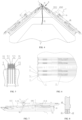
- the needle bed and needle combination includes a needle bed provided with a plurality of needle grooves 11, a plurality of parallel sinkers 13 provided at a front end of the needle bed, and knitting needles 51, 52 and stitch elements provided in the needle grooves.
- the needle bed and needle combinations are provided on each of the front and back sides of a frame 9 of a flat knitting machine through the needle bed 1.
- the two knitting needles 51, 52 are arranged on the left and right between every two sinkers on the needle bed 1, and the two knitting needles are separately configured to make knitting actions including a knit stitch, a tuck stitch and a loop transfer stitch.
- two parallel needle grooves 11 are arranged between every two sinkers on the needle bed. Specifically, the needle groove 11 formed through division by two steel pieces 15 is further divided by a separating piece 14 to form two parallel needle grooves 111 between every two sinkers.
- Each of the two knitting needles 51, 52 is provided in one of the corresponding needle grooves 111, respectively.
- the knitting needles 51, 52 are driven by the corresponding control stitch elements 63, 64 to move in the needle grooves 111, respectively, and the control stitch elements 63, 64 are driven by a corresponding cam on a cam plate.
- the stitch elements are the control stitch elements directly connected to the knitting needles as in this embodiment, and may also be composite stitch elements formed by combining two or more stitch elements.
- the knitting needles provided in the needle grooves are provided in parallel, with respective front ends positioned in close proximity to a strip-shaped opening (tooth-shaped opening) 91 formed by the sinkers 13 and the front end of the needle bed 1 for forming a knitted fabric 8 (Since the sinker is called tooth-shaped bit, the strip-shaped opening is also called tooth-shaped opening).
- the needle bed and needle combination includes a needle bed 1 provided with a plurality of parallel needle grooves 11 formed through division by steel pieces 15, a plurality of parallel sinkers 13 provided at a front end of the needle bed, and knitting needles 51, 52 provided in the needle grooves.
- the needle bed and needle combinations are provided on each of the front and back sides of a frame 9 of a flat knitting machine through the needle bed 1.
- the two knitting needles 51, 52 are arranged in parallel on the left and right in the needle groove between every two sinkers, and the two knitting needles are separately configured to make knitting actions including a knit stitch, a tuck stitch and a loop transfer stitch.
- one needle groove 11 is provided between every two sinkers on the needle bed, and two knitting needles are provided in parallel in the same needle groove 11.
- a needle selection unit 3a cooperates with a composite stitch element that includes elastic stitch elements 61, 62 and a control stitch element 60 to select one of the knitting needles to work (i.e., to be ejected) while the other is idled.
- the two parallel knitting needles in the same needle groove can separately make knitting actions including a knit stitch, a tuck stitch and a loop transfer stitch. Therefore, in this embodiment, the needle bed and needle combination is further provided with a needle selection mechanism, where the needle selection mechanism includes at least the needle selection unit 3a and the composite stitch element that includes the elastic stitch elements and the control stitch element.
- the two elastic stitch elements 61, 62 are connected to the two parallel knitting needles 51, 52, respectively.
- the two elastic stitch elements 61, 62 are engaged with the two parallel knitting needles 51, 52.
- the two elastic stitch elements 61, 62 are in one-to-one correspondence with the knitting needles 51, 52 and are arranged side by side in the needle groove 11.
- the control stitch element 60 is located above the two elastic stitch elements 61, 62, and is engaged with the two elastic stitch elements 61, 62.
- a support rod 12 supports the control stitch element 60, such that the control stitch element 60 is located above the two elastic stitch elements 61, 62.
- the support rod 12 is detachably provided in the needle groove 11 through two support steel wires 161 arranged on the needle bed.
- the needle selection unit operates on the elastic stitch element connected to the knitting needle that does not need to be ejected, such that the elastic stitch element is pressed and deformed elastically to disengage from the control stitch element.
- the knitting needle is not connected to the control stitch element 60 through the elastic stitch element and thus cannot be driven by the control stitch element 60 to perform the knitting action.
- the elastic stitch element can be driven by the control stitch element 60, so the knitting needles can make knitting actions including a knit stitch, a tuck stitch and a loop transfer stitch.
- both of the two elastic stitch elements are not operated on by the needle selection unit, and the needle selection unit is in an initial state at this time.
- FIGS. 8 to 10 show the needle selection unit 3a of this embodiment.
- the needle selection unit 3a includes at least a control element 30, a first pressing piece 3a1, and a second pressing piece 3a2.
- the first pressing piece 3a1 is provided with a pressing portion configured to press the corresponding elastic stitch element and a first control portion configured to be operated on by the control element.
- the second pressing piece 3a2 is provided with a pressing portion and a second control portion configured to be operated on by the control element.
- the two pressing pieces are respectively arranged above the corresponding elastic stitch elements, and the pressing portions of the two pressing pieces respectively face the corresponding elastic stitch elements.
- the first control portion and the second control portion are respectively located at different positions staggered from each other in a length direction of the needle groove, so as to be respectively operated on by the control element and moved downward after being operated on.
- the first pressing piece 3a1 and the second pressing piece 3a2 have the same structure and shape, and each of the first pressing piece 3a1 and the second pressing piece 3a2 includes a main body 3aa and a protrusion 3ab.
- the protrusion 3ab of the first pressing piece and the protrusion 3ab of the second pressing piece are provided at a side of upper ends of corresponding main bodies 3aa respectively to form a first control portion of the first pressing piece and a second control portion of the second pressing piece.
- a lower side of the main body of each of the first pressing piece and the second pressing piece forms a corresponding pressing portion 3ac.
- the first pressing piece 3a1 and the second pressing piece 3a2 are arranged side by side in the needle groove, with respective main bodies overlapped with each other.
- the protrusion 3ab of the first pressing piece and the protrusion 3ab of the second pressing piece are located at an upper left end of the first pressing piece 3a1 and an upper right end of the second pressing piece 3a2, respectively, and staggered from each other in a direction of the needle groove.
- the first pressing piece 3a1 and the second pressing piece 3a2 are located above the elastic stitch elements 61, 62, respectively.
- control elements are two pressing plates 301, 302 provided on a cam plate 2 of the flat knitting machine at positions corresponding to the first pressing piece and the second pressing piece, respectively, and adjustable up and down.
- Each of the two pressing plates is provided with an inclined surface configured to press the pressing piece.
- the pressing plate operates on the control portion (that is the corresponding protrusion 3ab) through the inclined surface to move the corresponding pressing piece downward. As shown in FIGS.
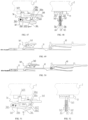
- the second pressing plate 302 located above the elastic stitch element 62 that is connected to the knitting needle 52, moves downward, such that the inclined surface 3021 of the second pressing plate 302 presses against the corresponding protrusion 3ab of the second pressing piece 3a2.
- the pressing plate 302 completely presses down the second pressing piece 3a2, and the elastic stitch element 62 is deformed elastically to disengage from the control stitch element 60, as shown in FIG. 16 .
- a returning force of elastic deformation of the elastic stitch element makes the corresponding pressing piece return to an original position, and the needle selection unit 3a returns to an initial state, as shown in FIG. 17 .
- the two pressing pieces are slidable up and down in the needle groove 11.
- the corresponding main body 3aa is provided with vertical guide surfaces 3aa1 on left and right sides and a vertical guide groove 3aa2 at a lower central position.
- the guide groove 3aa2 divides the first pressing portion and the second pressing portion at a lower side of the first pressing piece or the second pressing piece into two parts.
- the main body has a thickness of not greater than half a width of the needle groove.
- an upper end of the protrusion 3ab has a thickness adapted to the width of the needle groove, such that the protrusion 3ab is guided by the needle groove.
- Guide steel wires 162 are arranged on the needle bed, which correspond to the two guide surfaces 3aa1 and the guide groove 3aa2, respectively.
- the first pressing piece 3a1 or the second pressing piece 3a2 is slidable up and down along the guide steel wires 162.
- Lower sides of the elastic stitch elements are provided with limiting protrusions 611, 621, respectively.
- the bottom of the needle groove is provided with a limiting groove 18.
- the limiting groove limits front-back movement of the elastic stitch element.
- front ends of the two parallel knitting needles provided in the same needle groove are positioned in close proximity to a strip-shaped opening 91 formed by the sinkers 13 and the front end of the needle bed 1 for forming a knitted fabric 8.
- the needle bed and needle combination includes a needle bed 1 provided with a plurality of parallel needle grooves 11, a plurality of parallel sinkers 13 provided at a front end of the needle bed, and knitting needles 51, 52 provided in the needle grooves.
- the needle bed and needle combinations are provided on each of the front and back sides of a frame 9 of a flat knitting machine through the needle bed 1.
- One needle groove 11 is provided between every two sinkers on the needle bed, and two knitting needles 51, 52 are arranged on the left and right in the same needle groove 11 in a width direction of the needle groove.
- a needle selection unit 3b cooperates with a composite stitch element that includes elastic stitch elements 61, 62 and a control stitch element 60 to select one of the knitting needles to work (i.e., to be ejected) while the other is idled.
- the two parallel knitting needles in the same needle groove can separately make knitting actions including a knit stitch, a tuck stitch and a loop transfer stitch. Therefore, the needle bed and needle combinations of this embodiment and Embodiment 2 essentially only differ in the needle selection unit.
- FIGS. 20 and 21 show the needle selection unit 3b of this embodiment.
- the needle selection unit 3b includes at least a control element 30, a first pressing piece 3b1, and a second pressing piece 3b2.
- the first pressing piece 3b 1 is provided with a pressing portion configured to press the corresponding elastic stitch element and a first control portion configured to be operated on by the control element.
- the second pressing piece 3b2 is provided with a pressing portion and a second control portion configured to be operated on by the control element.
- the two pressing pieces are respectively arranged above the corresponding elastic stitch elements, and the pressing portions of the two pressing pieces respectively face the corresponding elastic stitch elements.
- the first control portion and the second control portion are respectively located at different positions staggered from each other in a length direction of the needle groove, so as to be respectively operated on by the control element and moved downward after being operated on to press the corresponding elastic stitch elements.
- the first pressing piece 3b1 and the second pressing piece 3b2 have the same structure and shape, and each of the first pressing piece 3b1 and the second pressing piece 3b2 includes a main body 3ba and a protrusion 3bb.
- the protrusion 3bb is provided at a side of an upper end of the main body 3ba to form the control portion of the corresponding pressing piece.
- Both of the main body and the protrusion have a thickness adapted to a width of the needle groove, and a side of the lower side of the main body is provided with a recess to form a lower side edge that is not greater than half the width of the needle groove, thereby forming a pressing portion 3bc of the corresponding pressing piece.
- the main body is provided with guide surfaces 3ba2, 3ba3 and a sliding surface 3ba1 at left and right sides, respectively.
- the two pressing pieces symmetrically touch each other with the sliding surface 3ba1 as a symmetrical central surface and are arranged side by side in the needle groove, such that the protrusions 3bb and the guide surfaces 3ba2, 3ba3 of the two pressing pieces are arranged symmetrically with respect to the symmetrical central surface.
- the recess forming the pressing portion 3bc faces a central surface of the needle groove, and the respective pressing portion 3bc is located above the respective elastic stitch element.
- the needle bed is provided with guide steel wires 162 corresponding to a side of the guide surfaces of the two pressing pieces.
- the first pressing piece 3b 1 is slidable up and down along the guide steel wires 162 corresponding to a side of the guide surface of the pressing plate and the sliding surface of the second pressing piece 3b2.
- the second pressing piece 3b2 is slidable up and down along the guide steel wires 162 corresponding to a side of the guide surface of the pressing plate and the sliding surface of the first pressing piece 3b 1. Therefore, the two pressing pieces are slidable up and down relative to each other.
- the control elements are two pressing plates 301, 302 provided on a cam plate of the flat knitting machine at positions corresponding to the first pressing piece 3b1 and the second pressing piece 3b2, respectively, and adjustable up and down.
- Each of the two pressing plates is provided with an inclined surface.
- the pressing plate operates on the control portion (that is the corresponding protrusion 3bb) through the inclined surface. For example, if it is necessary to eject the knitting needle 51 while maintaining the knitting needle 52 to be idled, the second pressing plate 302, located above the elastic stitch element 62 that is connected to the knitting needle 52, moves downward, as shown in FIG.
- the needle bed and needle combination includes a needle bed 1 provided with a plurality of parallel needle grooves 11, a plurality of parallel sinkers 13 provided at a front end of the needle bed, and knitting needles 51, 52 provided in the needle grooves.
- the needle bed and needle combinations are provided on each of the front and back sides of a frame 9 of a flat knitting machine through the needle bed 1.
- One needle groove 11 is provided between every two sinkers on the needle bed, and two parallel knitting needles 51, 52 are arranged on the left and right in the same needle groove 11 in a width direction of the needle groove.
- a needle selection unit 3c cooperates with a composite stitch element that includes elastic stitch elements 61, 62 and a control stitch element 60 to select one of the knitting needles to work (i.e., to be ejected) while the other is idled.
- the two parallel knitting needles in the same needle groove can separately make knitting actions including a knit stitch, a tuck stitch and a loop transfer stitch. Therefore, the needle bed and needle combinations of this embodiment and Embodiment 2 or Embodiment 3 essentially only differ in the needle selection unit.
- FIGS. 31 and 32 show the needle selection unit 3c of this embodiment.
- the needle selection unit 3c includes at least a control element 30, a first pressing piece 3c1, and a second pressing piece 3c2.
- the first pressing piece 3c1 is provided with a pressing portion configured to press the corresponding elastic stitch element and a first control portion configured to be operated on by the control element.
- the second pressing piece 3c2 is provided with a pressing portion and a second control portion configured to be operated on by the control element.
- the two pressing pieces are respectively arranged above the corresponding elastic stitch elements, and the pressing portions of the two pressing pieces respectively face the corresponding elastic stitch elements.
- the first control portion and the second control portion are respectively located at different positions staggered from each other in a length direction of the needle groove, so as to be respectively operated on by the control element and rotate the corresponding pressing pieces downward after being operated on to press the corresponding elastic stitch elements.
- the first pressing piece 3c1 and the second pressing piece 3c2 are provided coaxially rotatable in the needle groove 11.
- the first pressing piece 3c1 and the second pressing piece 3c2 have the same structure and shape, and each of the first pressing piece 3c1 and the second pressing piece 3c2 includes a main body 3ca and a protrusion 3cb.
- the protrusion 3cb of the first pressing piece is provided at an upper center right side position of the corresponding main body to form the first control portion of the first pressing piece.
- the protrusion 3cb of the second pressing piece is provided at an upper right end position of the corresponding main body to form the second control portion of the second pressing piece.
- Lower sides of the main bodies 3ca of the two pressing pieces are provided with pressing portions 3cc in a downwardly contracted triangular shape.
- the main body 3ca has a thickness of not greater than half a width of the needle groove.
- the protrusion 3cb is provided with an L-shaped recess surface opposite to an inner side of the needle groove.
- An upper end of the protrusion has a thickness adapted to the width of the needle groove.
- the L-shaped recess surfaces on the two pressing pieces are symmetrically arranged with respect to a central surface of the needle groove.
- the needle bed is provided with a rotating steel wire 164 corresponding to the rotating holes, and provided with a limiting steel wire 163 located above upper sides of the two pressing pieces.
- the first pressing piece and the second pressing piece are provided in the needle groove 11 and rotatable by the rotating steel wire 164 passing through the rotating holes 3cd.
- the limiting steel wire 163 limits movement of the two pressing pieces 3c1, 3c2 caused by a returning force of the elastic stitch elements 61, 62.
- control elements are two pressing plates 301, 302 provided on a cam plate 2 of the flat knitting machine at positions corresponding to the two pressing pieces, respectively.
- Each of the two pressing plates is provided with an inclined surface. If it is necessary to eject the knitting needle 51 while maintaining the knitting needle 52 to be idled, the second pressing plate 302, located above the elastic stitch element 62 that is connected to the knitting needle 52, moves downward, such that the inclined surface 3021 of the second pressing plate 302 presses against the corresponding protrusion 3cb of the second pressing piece 3c2, as shown in FIG. 37 .
- the second pressing plate 302 When moving with the cam plate, the second pressing plate 302 operates on the protrusion 3cb of the second pressing piece 3c2 through the inclined surface to rotate the second pressing piece 3c2 until a lower end surface of the second pressing plate 302 completely presses the second pressing piece 3c2, as shown in FIGS. 38 and 39 .
- the elastic stitch element 62 is pressed to be deformed elastically to disengage from the control stitch element 60, as shown in FIG. 40 .
- a returning force of elastic deformation of the elastic stitch element 62 makes the pressing piece 3c2 return to an original position, and the needle selection unit 3c returns to an initial state, as shown in FIG. 41 .
- the needle bed and needle combination includes a needle bed 1 provided with a plurality of parallel needle grooves 11, a plurality of parallel sinkers 13 provided at a front end of the needle bed, and knitting needles 51, 52 provided in the needle grooves.
- the needle bed and needle combinations are provided on each of the front and back sides of a frame 9 of a flat knitting machine through the needle bed 1.
- One needle groove 11 is provided between every two sinkers on the needle bed, and two knitting needles 51, 52 are arranged on the left and right in the same needle groove 11 in a width direction of the needle groove.
- a needle selection unit 3d cooperates with a composite stitch element that includes elastic stitch elements 61, 62 and a control stitch element 60 to select one of the knitting needles to work (i.e., to be ejected) while the other is idled.
- the two parallel knitting needles in the same needle groove can separately make knitting actions including a knit stitch, a tuck stitch and a loop transfer stitch. Therefore, the needle bed and needle combinations of this embodiment and Embodiment 2 essentially only differ in the needle selection unit.
- FIGS. 45 and 46 show the needle selection unit 3d of this embodiment.
- the needle selection unit 3d further includes a push piece 3d3.
- the first pressing piece 3d1 is provided with a pressing portion and a first control portion configured to be operated on by the control element
- the second pressing piece 3d2 is provided with a pressing portion and a second control portion configured to be operated on by the control element.
- the two pressing pieces are respectively arranged above the corresponding elastic stitch elements 61, 62.
- the first control portion and the second control portion are respectively located at different positions staggered from each other in a length direction of the needle groove.
- the control element operates on the first control portion or the second control portion through the push piece 3d3. After being operated on, the first control portion or the second control portion rotates the corresponding pressing piece downward so as to press the corresponding elastic stitch element.
- the first pressing piece 3d1 and the second pressing piece 3d2 are provided coaxially rotatable in the needle groove 11, and each of the first pressing piece 3d 1 and the second pressing piece 3d2 includes a main body 3da and a protrusion.
- the main bodies 3da of the first pressing piece 3d1 and the second pressing piece 3d2 have the same structure and shape (such as the hatched portion of the first pressing piece in FIG. 47 ), but the corresponding protrusions are different in structure, that is, there are two types of protrusions, a first protrusion 3db1 and a second protrusion 3db2.
- the first protrusion 3db1 is provided with a climbing surface 3dbp, a descending surface 3dbx, and an upper end surface 3dbs connecting upper ends of the climbing surface and the descending surface.
- the second protrusion is provided with at least a climbing surface 3dbp and an upper end surface 3dbs connected to an upper end of the climbing surface. Furthermore, a distance between the first protrusion and the rotation center is smaller than a distance between the second protrusion and the rotation center.
- Lower sides of the main bodies 3da of the two pressing pieces are provided with pressing portions 3dc in a downwardly contracted triangular shape, and the pressing portions 3dc are located above the corresponding elastic stitch elements 61, 62.
- a first protrusion 3db1 and a second protrusion 3db2 are provided on upper sides of the main bodies 3da of the first pressing piece 3d1 and the second pressing piece 3d2, respectively.
- Rotating holes 3dd are respectively provided at identical positions on the same side of the main bodies of the two pressing pieces.
- a rotating steel wire 164 is provided at a position of the needle bed 1 corresponding to the rotating holes 3dd of the two pressing pieces, such that the two pressing pieces are provided coaxially rotatable in the needle groove 11 by the rotating steel wire 164 passing through the rotating holes.
- the push piece 3d3 is provided above the first pressing piece 3d1 and the second pressing piece 3d2.
- the push piece has a thickness adapted to a width of the needle groove.
- the push piece 3d3 is provided with a needle butt 3d31 and a push pin 3d32 at upper and lower sides, respectively.
- the corresponding main bodies 3da and protrusions of the two pressing pieces have the same thickness, which is not greater than half a width of the needle groove.
- the upper and lower sides of the push piece 3d3 are respectively provided with a stopper 17 and guide steel wires 162, such that the push piece is slidable between the stopper and the limiting steel wire.
- the first pressing piece 3d1 and the second pressing piece 3d2 are provided in the needle groove 11 and rotatable by the rotating steel wire 164 passing through the rotating holes 3dd.
- control element 31 is a push plate 31 provided on a cam plate of the flat knitting machine, and movable in a direction of the needle groove.
- the push plate 31 is provided with a guide groove 311 adapted to the needle butt.
- the push plate 31 is movable in the direction of the needle groove to move the push piece 3d3 to an initial position where the push pin 3d32 of the push piece 3d3 does not touch the first protrusion or the second protrusion, as shown in FIGS. 45 and 46 .
- the push piece 3d3 is also moved to a position where the push pin 3d32 of the push piece 3d3 touches the first protrusion 3db1, as shown in FIGS. 47 and 48 .
- the push pin 3d32 touches the climbing surface of the first protrusion to rotate the first pressing piece 3d1 downward until the push pin 3d32 operates on the upper end surface 3dbs along the climbing surface 3dbp, such that the pressing portion of the first pressing piece is at a lowermost position, thereby pressing the elastic stitch element 61 below to produce maximum elastic deformation to disengage from the knitting needle 51, as shown in FIG. 49 .
- the push pin touches the climbing surface of the second protrusion to rotate the second pressing piece 3d2 downward until the second pressing piece 3d2 presses against the corresponding upper end surface, such that the corresponding elastic stitch element 62 is deformed elastically to disengage from the corresponding knitting needle.
- the push pin of the push plate leaves the second protrusion, that is, when the push pin of the push plate is completely separated from the second pressing piece 3d2, the pressing operation of the push piece on the second pressing piece is removed, the elastic stitch element 62 is no longer pressed by the second pressing piece, and the pressing piece returns to an original position due to a returning force of elastic deformation of the elastic stitch element 62.
- this embodiment provides a needle bed and needle combination.
- the needle bed and needle combination includes a needle bed 1 provided with a plurality of needle grooves 11, a plurality of parallel sinkers 13 provided at a front end of the needle bed, knitting needles 51, 52 and control stitch elements 65, 66 provided in the needle grooves.
- the needle bed and needle combinations are provided on each of the front and back sides of a frame 9 of a flat knitting machine through the needle bed 1.
- Two knitting needles 52, 53 are arranged on the left and right in the needle groove 11 between every two sinkers in a width direction of the needle groove, and are arranged at an angle with each other in their respective needle grooves in a length direction.
- the knitting needles 51, 52 are respectively connected to the control stitch elements 65, 66, and the two knitting needles are separately driven by the corresponding control stitch elements to make knitting actions including a knit stitch, a tuck stitch and a loop transfer stitch.
- the two needle grooves corresponding to the two knitting needles are a needle groove 111 and a needle groove 112, which are formed through further divided by a separating piece 14 from needle groove 11 formed through division by two steel pieces 15.
- the needle groove 111 has a bottom surface that is substantially parallel with an upper end surface of the needle bed 1. Bottom surfaces of the needle groove 111 and the needle groove 112 are relatively inclined to form an angle ⁇ , where ⁇ is generally not greater than 40°. Therefore, the bottom surfaces of the needle groove 111 and the needle groove 112 are different surfaces, such that the two knitting needles 51, 52 provided in the needle groove 111 and the needle groove 112 are at an angle ⁇ in a length direction. Front ends of the two knitting needles 51, 52 are positioned in close proximity to a strip-shaped opening in an initial state, as shown in FIGS. 55 and 56 .
- two knitting needles are arranged between every two sinkers with the same spacing, increasing the number of knitting needles without increasing the number of sinkers, and maximizing usage of the lateral space of the needle bed.
- the flat knitting machine with double needle beds can produce three-dimensional knitted fabric with a standard gauge.
- the two knitting needles arranged on the left and right between every two adjacent sinkers are positioned in close proximity to the strip-shaped opening, so the two knitting needles which knit separately have the same knitting effect. Therefore, the flat knitting machine of the present disclosure has a simple on-machine process and is easy to operate.
Landscapes
- Engineering & Computer Science (AREA)
- Textile Engineering (AREA)
- Knitting Machines (AREA)
Applications Claiming Priority (2)
| Application Number | Priority Date | Filing Date | Title |
|---|---|---|---|
| CN202010316107.2A CN111334923B (zh) | 2020-04-21 | 2020-04-21 | 一种横编织机用针板织针组合及织针选择机构 |
| PCT/CN2021/080910 WO2021213077A1 (fr) | 2020-04-21 | 2021-03-16 | Combinaison de plaque d'aiguille et d'aiguilles à tricoter pour machine à tricoter rectiligne, et mécanisme de sélection d'aiguille à tricoter |
Publications (2)
| Publication Number | Publication Date |
|---|---|
| EP4130367A1 true EP4130367A1 (fr) | 2023-02-08 |
| EP4130367A4 EP4130367A4 (fr) | 2024-02-14 |
Family
ID=71182844
Family Applications (1)
| Application Number | Title | Priority Date | Filing Date |
|---|---|---|---|
| EP21792413.3A Pending EP4130367A4 (fr) | 2020-04-21 | 2021-03-16 | Combinaison de plaque d'aiguille et d'aiguilles à tricoter pour machine à tricoter rectiligne, et mécanisme de sélection d'aiguille à tricoter |
Country Status (6)
| Country | Link |
|---|---|
| US (1) | US20230146969A1 (fr) |
| EP (1) | EP4130367A4 (fr) |
| JP (1) | JP7473138B2 (fr) |
| KR (1) | KR102787737B1 (fr) |
| CN (1) | CN111334923B (fr) |
| WO (1) | WO2021213077A1 (fr) |
Families Citing this family (6)
| Publication number | Priority date | Publication date | Assignee | Title |
|---|---|---|---|---|
| CN111334923B (zh) * | 2020-04-21 | 2020-12-22 | 冯加林 | 一种横编织机用针板织针组合及织针选择机构 |
| CN111733512B (zh) * | 2020-07-13 | 2024-04-09 | 桐乡市强隆机械有限公司 | 单槽双针针板装置 |
| CN111945287B (zh) * | 2020-08-21 | 2024-08-20 | 浙江丰帆数控机械有限公司 | 一种针织横机的针床装置及针织横机 |
| CN112281291A (zh) * | 2020-10-13 | 2021-01-29 | 孙荣飞 | 一种横机的双织针组合机构 |
| CN112981688B (zh) * | 2021-02-24 | 2023-06-16 | 张家港市文杰机械有限公司 | 针织横机织针选择机构 |
| CN116121945B (zh) * | 2023-01-18 | 2026-03-27 | 浙江百信针织机械有限公司 | 一种具有织针选择机构的电脑横机针板 |
Family Cites Families (19)
| Publication number | Priority date | Publication date | Assignee | Title |
|---|---|---|---|---|
| US3115760A (en) * | 1960-08-23 | 1963-12-31 | Ralph C Powell | Method and machine for knitting seamless gloves |
| DE2315334A1 (de) * | 1973-03-28 | 1974-10-10 | Stoll & Co H | Strickmaschine, insbesondere flachstrickmaschine |
| JPS6221850A (ja) * | 1985-07-19 | 1987-01-30 | 株式会社島精機製作所 | 複合針を使用した横編機 |
| JPS6468547A (en) * | 1987-09-04 | 1989-03-14 | Shima Seiki Mfg | Traverse knitting machine |
| JP2726959B2 (ja) * | 1991-08-29 | 1998-03-11 | 株式会社島精機製作所 | 横編地の編成方法及び多段ベッド横編機 |
| JP2724676B2 (ja) * | 1994-03-17 | 1998-03-09 | 株式会社島精機製作所 | 横編機 |
| JPH07324260A (ja) * | 1994-05-27 | 1995-12-12 | Shima Seiki Mfg Ltd | 進入防止片を備えた横編機 |
| JP3406085B2 (ja) * | 1994-10-12 | 2003-05-12 | 株式会社島精機製作所 | 筒状編地の編み幅側縁部に縄柄を編成する方法 |
| KR0148422B1 (ko) * | 1994-10-14 | 1999-02-18 | 류기철 | 철도차량 하부 프레임 선행배관 작업방법 및 그 장치 |
| US5694792A (en) * | 1995-06-15 | 1997-12-09 | Shima Seiki Manufacturing, Ltd. | Needle selection device of flat knitting machine |
| CN1274894C (zh) * | 2003-11-14 | 2006-09-13 | 冯加林 | 一种横机用压线、脱线装置 |
| JP4374313B2 (ja) | 2004-12-28 | 2009-12-02 | 株式会社島精機製作所 | 横編機 |
| DE102008061699A1 (de) * | 2008-12-11 | 2010-06-17 | Sipra Patententwicklungs- Und Beteiligungsgesellschaft Mbh | Strickmaschine zur Herstellung von mit Mustern versehenen Strickwaren |
| CN102947498A (zh) * | 2010-06-04 | 2013-02-27 | 尚和手套株式会社 | 织针引导结构、织针、编织方法、编织物和手套 |
| PT3124664T (pt) * | 2015-07-30 | 2020-03-23 | Groz Beckert Kg | Método e dispositivo para a formação de laço |
| EP3124663B1 (fr) * | 2015-07-30 | 2019-10-16 | Groz-Beckert KG | Procédé et dispositif de formation de boucles |
| DE102017223750B4 (de) | 2017-12-22 | 2021-10-07 | Adidas Ag | Gestrickte oder gewirkte Komponente |
| CN208501211U (zh) * | 2018-07-05 | 2019-02-15 | 蒋伊柠 | 横机织针面板结构及包含它的横机 |
| CN111334923B (zh) * | 2020-04-21 | 2020-12-22 | 冯加林 | 一种横编织机用针板织针组合及织针选择机构 |
-
2020
- 2020-04-21 CN CN202010316107.2A patent/CN111334923B/zh active Active
-
2021
- 2021-03-16 JP JP2022542489A patent/JP7473138B2/ja active Active
- 2021-03-16 EP EP21792413.3A patent/EP4130367A4/fr active Pending
- 2021-03-16 WO PCT/CN2021/080910 patent/WO2021213077A1/fr not_active Ceased
- 2021-03-16 US US17/920,417 patent/US20230146969A1/en active Pending
- 2021-03-16 KR KR1020227040360A patent/KR102787737B1/ko active Active
Also Published As
| Publication number | Publication date |
|---|---|
| EP4130367A4 (fr) | 2024-02-14 |
| JP7473138B2 (ja) | 2024-04-23 |
| US20230146969A1 (en) | 2023-05-11 |
| WO2021213077A1 (fr) | 2021-10-28 |
| CN111334923A (zh) | 2020-06-26 |
| CN111334923B (zh) | 2020-12-22 |
| JP2023511269A (ja) | 2023-03-17 |
| KR20230024262A (ko) | 2023-02-20 |
| KR102787737B1 (ko) | 2025-03-26 |
Similar Documents
| Publication | Publication Date | Title |
|---|---|---|
| EP4130367A1 (fr) | Combinaison de plaque d'aiguille et d'aiguilles à tricoter pour machine à tricoter rectiligne, et mécanisme de sélection d'aiguille à tricoter | |
| CN217809899U (zh) | 一种双系统三角总成 | |
| US5931025A (en) | Lowering sinker actuation cam set for circular knitting machines for forming standard-terry knitting and sandwich-terry knitting | |
| JP6105009B2 (ja) | 横編機によるパイル編成方法 | |
| CN112030332A (zh) | 一种电脑横机成衣编织用的组合式针床 | |
| CN116971083B (zh) | 一种高效稳定的横机山板 | |
| CN201358352Y (zh) | 一种电脑针织横机的三角编织机构 | |
| US3248901A (en) | Straight bar knitting machines | |
| CN212451841U (zh) | 一种电脑横机成衣编织用的组合式针床 | |
| CN211057361U (zh) | 一种双针筒织机成圈机构 | |
| CN104499178B (zh) | 一种采用多级选针的五功位电脑横机编织机构 | |
| US6257026B1 (en) | Needle control device for stocking knitting machines | |
| US2106872A (en) | Circular knitting machine | |
| US20030089135A1 (en) | Circular hosiery machines with needles on the cylinder and in the bed plate, in particular for terry fabric | |
| JP6557430B1 (ja) | 歯口隙間の大きさが変更可能な横編機構造 | |
| US2775107A (en) | Circular rib knitting machine | |
| CN201317857Y (zh) | 一种能实现成圈、集圈和移圈编织的三角编织机构 | |
| CN106087228A (zh) | 一种针织圆机的对针编织结构 | |
| US3331218A (en) | Knitting machine having laterally deflectable needles | |
| CN223753002U (zh) | 上下盘提花大圆机的上盘无接针提花结构 | |
| CN215404837U (zh) | 一种具有多针道的山板 | |
| CN203904610U (zh) | 一种纬编割圈绒机 | |
| US2038735A (en) | Flat knitting machine | |
| CN210596494U (zh) | 一种四梳栉高速经编机 | |
| CN103603129B (zh) | 用于实现无规则单面嵌花的三角装置 |
Legal Events
| Date | Code | Title | Description |
|---|---|---|---|
| STAA | Information on the status of an ep patent application or granted ep patent |
Free format text: STATUS: THE INTERNATIONAL PUBLICATION HAS BEEN MADE |
|
| PUAI | Public reference made under article 153(3) epc to a published international application that has entered the european phase |
Free format text: ORIGINAL CODE: 0009012 |
|
| STAA | Information on the status of an ep patent application or granted ep patent |
Free format text: STATUS: REQUEST FOR EXAMINATION WAS MADE |
|
| 17P | Request for examination filed |
Effective date: 20221027 |
|
| AK | Designated contracting states |
Kind code of ref document: A1 Designated state(s): AL AT BE BG CH CY CZ DE DK EE ES FI FR GB GR HR HU IE IS IT LI LT LU LV MC MK MT NL NO PL PT RO RS SE SI SK SM TR |
|
| DAV | Request for validation of the european patent (deleted) | ||
| DAX | Request for extension of the european patent (deleted) | ||
| REG | Reference to a national code |
Ref country code: DE Ref legal event code: R079 Free format text: PREVIOUS MAIN CLASS: D04B0007040000 Ipc: D04B0015700000 |
|
| RIC1 | Information provided on ipc code assigned before grant |
Ipc: D04B 7/28 20060101ALN20230926BHEP Ipc: D04B 15/70 20060101AFI20230926BHEP |
|
| A4 | Supplementary search report drawn up and despatched |
Effective date: 20240115 |
|
| RIC1 | Information provided on ipc code assigned before grant |
Ipc: D04B 7/28 20060101ALN20240109BHEP Ipc: D04B 15/70 20060101AFI20240109BHEP |
|
| STAA | Information on the status of an ep patent application or granted ep patent |
Free format text: STATUS: EXAMINATION IS IN PROGRESS |
|
| 17Q | First examination report despatched |
Effective date: 20240703 |
|
| GRAP | Despatch of communication of intention to grant a patent |
Free format text: ORIGINAL CODE: EPIDOSNIGR1 |
|
| STAA | Information on the status of an ep patent application or granted ep patent |
Free format text: STATUS: GRANT OF PATENT IS INTENDED |