EP4130392A1 - Tiefgründungsbagger - Google Patents
Tiefgründungsbagger Download PDFInfo
- Publication number
- EP4130392A1 EP4130392A1 EP21781835.0A EP21781835A EP4130392A1 EP 4130392 A1 EP4130392 A1 EP 4130392A1 EP 21781835 A EP21781835 A EP 21781835A EP 4130392 A1 EP4130392 A1 EP 4130392A1
- Authority
- EP
- European Patent Office
- Prior art keywords
- raising
- opening
- lowering
- closing
- cylinder
- Prior art date
- Legal status (The legal status is an assumption and is not a legal conclusion. Google has not performed a legal analysis and makes no representation as to the accuracy of the status listed.)
- Pending
Links
Images


Classifications
-
- E—FIXED CONSTRUCTIONS
- E02—HYDRAULIC ENGINEERING; FOUNDATIONS; SOIL SHIFTING
- E02F—DREDGING; SOIL-SHIFTING
- E02F3/00—Dredgers; Soil-shifting machines
- E02F3/04—Dredgers; Soil-shifting machines mechanically-driven
- E02F3/46—Dredgers; Soil-shifting machines mechanically-driven with reciprocating digging or scraping elements moved by cables or hoisting ropes ; Drives or control devices therefor
-
- E—FIXED CONSTRUCTIONS
- E02—HYDRAULIC ENGINEERING; FOUNDATIONS; SOIL SHIFTING
- E02F—DREDGING; SOIL-SHIFTING
- E02F9/00—Component parts of dredgers or soil-shifting machines, not restricted to one of the kinds covered by groups E02F3/00 - E02F7/00
- E02F9/20—Drives; Control devices
- E02F9/22—Hydraulic or pneumatic drives
- E02F9/2221—Control of flow rate; Load sensing arrangements
- E02F9/2225—Control of flow rate; Load sensing arrangements using pressure-compensating valves
- E02F9/2228—Control of flow rate; Load sensing arrangements using pressure-compensating valves including an electronic controller
-
- E—FIXED CONSTRUCTIONS
- E02—HYDRAULIC ENGINEERING; FOUNDATIONS; SOIL SHIFTING
- E02F—DREDGING; SOIL-SHIFTING
- E02F3/00—Dredgers; Soil-shifting machines
- E02F3/04—Dredgers; Soil-shifting machines mechanically-driven
- E02F3/28—Dredgers; Soil-shifting machines mechanically-driven with digging tools mounted on a dipper- or bucket-arm, i.e. there is either one arm or a pair of arms, e.g. dippers, buckets
- E02F3/36—Component parts
- E02F3/40—Dippers; Buckets ; Grab devices, e.g. manufacturing processes for buckets, form, geometry or material of buckets
- E02F3/413—Dippers; Buckets ; Grab devices, e.g. manufacturing processes for buckets, form, geometry or material of buckets with grabbing device
- E02F3/4135—Dippers; Buckets ; Grab devices, e.g. manufacturing processes for buckets, form, geometry or material of buckets with grabbing device with grabs mounted directly on a boom
-
- E—FIXED CONSTRUCTIONS
- E02—HYDRAULIC ENGINEERING; FOUNDATIONS; SOIL SHIFTING
- E02F—DREDGING; SOIL-SHIFTING
- E02F3/00—Dredgers; Soil-shifting machines
- E02F3/04—Dredgers; Soil-shifting machines mechanically-driven
- E02F3/46—Dredgers; Soil-shifting machines mechanically-driven with reciprocating digging or scraping elements moved by cables or hoisting ropes ; Drives or control devices therefor
- E02F3/47—Dredgers; Soil-shifting machines mechanically-driven with reciprocating digging or scraping elements moved by cables or hoisting ropes ; Drives or control devices therefor with grab buckets
- E02F3/475—Dredgers; Soil-shifting machines mechanically-driven with reciprocating digging or scraping elements moved by cables or hoisting ropes ; Drives or control devices therefor with grab buckets for making foundation slots
-
- E—FIXED CONSTRUCTIONS
- E02—HYDRAULIC ENGINEERING; FOUNDATIONS; SOIL SHIFTING
- E02F—DREDGING; SOIL-SHIFTING
- E02F3/00—Dredgers; Soil-shifting machines
- E02F3/04—Dredgers; Soil-shifting machines mechanically-driven
- E02F3/46—Dredgers; Soil-shifting machines mechanically-driven with reciprocating digging or scraping elements moved by cables or hoisting ropes ; Drives or control devices therefor
- E02F3/58—Component parts
-
- E—FIXED CONSTRUCTIONS
- E02—HYDRAULIC ENGINEERING; FOUNDATIONS; SOIL SHIFTING
- E02F—DREDGING; SOIL-SHIFTING
- E02F9/00—Component parts of dredgers or soil-shifting machines, not restricted to one of the kinds covered by groups E02F3/00 - E02F7/00
- E02F9/14—Booms only for booms with cable suspension arrangements; Cable suspensions
-
- E—FIXED CONSTRUCTIONS
- E02—HYDRAULIC ENGINEERING; FOUNDATIONS; SOIL SHIFTING
- E02F—DREDGING; SOIL-SHIFTING
- E02F9/00—Component parts of dredgers or soil-shifting machines, not restricted to one of the kinds covered by groups E02F3/00 - E02F7/00
- E02F9/20—Drives; Control devices
- E02F9/22—Hydraulic or pneumatic drives
- E02F9/2264—Arrangements or adaptations of elements for hydraulic drives
- E02F9/2267—Valves or distributors
-
- E—FIXED CONSTRUCTIONS
- E02—HYDRAULIC ENGINEERING; FOUNDATIONS; SOIL SHIFTING
- E02F—DREDGING; SOIL-SHIFTING
- E02F9/00—Component parts of dredgers or soil-shifting machines, not restricted to one of the kinds covered by groups E02F3/00 - E02F7/00
- E02F9/20—Drives; Control devices
- E02F9/22—Hydraulic or pneumatic drives
- E02F9/2278—Hydraulic circuits
- E02F9/2282—Systems using center bypass type changeover valves
-
- E—FIXED CONSTRUCTIONS
- E02—HYDRAULIC ENGINEERING; FOUNDATIONS; SOIL SHIFTING
- E02F—DREDGING; SOIL-SHIFTING
- E02F9/00—Component parts of dredgers or soil-shifting machines, not restricted to one of the kinds covered by groups E02F3/00 - E02F7/00
- E02F9/20—Drives; Control devices
- E02F9/22—Hydraulic or pneumatic drives
- E02F9/2278—Hydraulic circuits
- E02F9/2292—Systems with two or more pumps
-
- E—FIXED CONSTRUCTIONS
- E02—HYDRAULIC ENGINEERING; FOUNDATIONS; SOIL SHIFTING
- E02F—DREDGING; SOIL-SHIFTING
- E02F9/00—Component parts of dredgers or soil-shifting machines, not restricted to one of the kinds covered by groups E02F3/00 - E02F7/00
- E02F9/20—Drives; Control devices
- E02F9/22—Hydraulic or pneumatic drives
- E02F9/2278—Hydraulic circuits
- E02F9/2296—Systems with a variable displacement pump
Definitions
- the present invention relates to deep foundation excavators to be used suitably for excavating a vertical shaft.
- the deep foundation excavator is provided with an automotive vehicle body and a working mechanism disposed in the vehicle body.
- This working mechanism is provided with a boom disposed in the vehicle body, an arm disposed in a tip end of the boom, a bucket raising/lowering device disposed in the arm and a clamshell bucket.
- the clamshell bucket is disposed to be capable of raising and lowering to the arm, and the vertical shaft is excavated by a raising/lowering movement and an opening/closing movement of the bucket raising/lowering device.
- a device which is provided with a raising/lowering cylinder for raising and lowering a clamshell bucket and an opening/closing cylinder for opening and closing the clamshell bucket, is proposed as a bucket raising/lowering device of this kind (Patent Document 1).
- the raising/lowering cylinder changes an interval between a movable sheave and a fixed sheave to wind off or wind up a raising/lowering rope to raise or lower the clamshell bucket.
- the opening/closing cylinder changes an interval between a movable sheave and a fixed sheave to wind off or wind up an opening/closing rope to open or close the clamshell bucket.
- the bucket raising/lowering device is configured so that by detecting the landing of the clamshell bucket on the ground, the lowering of the bucket by the raising/lowering cylinder is stopped, which prevents the raising/lowering rope from leaving from the sheave due to the slacking of the raising/lowering rope.
- a device is proposed as another bucket raising/lowering device according to the conventional technology, which is configured so that a drum, around which a raising/lowering rope and an opening/closing rope are wound, is disposed in a boom.
- This drum is switched to three forms of the raising and the lowering of the clamshell bucket, and the lowering by its own weight (free dropping) (Patent Document 2).
- Patent Document 2 a lower end of a swing link is attached to an arm attached on the boom.
- the opening/closing rope for connection between the drum and the clamshell bucket is wound around a sheave disposed in an upper end of the swing link.
- the bucket raising/lowering device is configured so that the swing link is caused to swing by expanding and contracting a cylinder connected to the swing link to open and close the clamshell bucket.
- the bucket raising/lowering device enables the clamshell bucket to get into under the ground by its own weight by making the drum in the form of free dropping.
- the clamshell bucket is closed by swinging the swing link in a state where the clamshell bucket is getting into under the ground.
- the bucket raising/lowering device can excavate a lot of sand and earth by an excavating movement one time to enhance an excavating efficiency.
- the bucket raising/lowering device according to Patent Document 2 needs to cause the swing link mounted on the arm to swing for opening and closing the clamshell bucket. Therefore, a height of a vehicle body including a range in which the swing link swings at the excavating work becomes large, posing a problem of being incapable of applying this device to a working site having a height limitation, such as a site of executing an inverted construction method.
- An object of the present invention is to provide a deep foundation excavator that can enhance an excavating efficiency of sand and earth and suppress a height of a vehicle body at the excavating work.
- An aspect of the present invention is provided with a deep foundation excavator comprising:
- the raising/lowering cylinder is further operated after landing the clamshell bucket on the ground by the operation of the raising/lowering cylinder, thus enabling the raising/lowering rope and the opening/closing rope to be slacked.
- the slack adjustment cylinder is operated to remove the slack of the opening/closing rope, and thereafter, the clamshell bucket can quickly be closed by operating the opening/closing cylinder.
- the raising/lowering rope has the slack
- the clamshell bucket can get into under the ground by its own weight. Accordingly, since the clamshell bucket can shovel a lot of sand and earth by closing the clamshell bucket, the excavating efficiency can be enhanced.
- Fig. 1 to Fig. 9 show a first embodiment of the present invention.
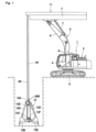
- a deep foundation excavator 1 is manufactured on the basis of a crawler-type hydraulic excavator, for example.
- the deep foundation excavator 1 is configured of an automotive lower traveling structure 2 of a crawler type, an upper revolving structure 3 mounted on the lower traveling structure 2 to be capable of revolving thereto and an after-mentioned working mechanism 5 disposed on the upper revolving structure 3.
- the lower traveling structure 2 and the upper revolving structure 3 configure a vehicle body of the deep foundation excavator 1.
- a cab 4 defining an operator' s room is disposed in a left front side of the upper revolving structure 3.
- An operator gets in the cab 4 for operating the lower traveling structure 2, the working mechanism 5 and the like.
- An operator's seat (not shown) on which an operator sits is disposed in the cab 4, and a raising/lowering operation pedal 36, an opening/closing operation lever 39 and a slack operation pedal 42, which will be described later, and the like are arranged in the periphery of the operator's seat.
- the working mechanism 5 is configured of a boom 6 attached on the upper revolving structure 3 to be capable of tilting and lifting thereto, an arm 7 disposed on a tip end of the boom 6 to be rotatable thereto, an after-mentioned bucket raising/lowering and opening/closing device 11 and a clamshell bucket 10.
- a boom cylinder 8 is disposed between the upper revolving structure 3 and the boom 6 to tilt and lift the boom 6 to the upper revolving structure 3.
- An arm cylinder 9 is disposed between the boom 6 and the arm 7 to rotate the arm 7 to the boom 6.
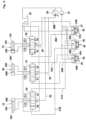
- the arm 7 is formed in a long square cylindrical body, for example. As shown in Fig. 2 , the bucket raising/lowering and opening/closing device 11 is mounted on the arm 7. A raising/lowering guide sheave 22 and an opening/closing guide sheave 23 are arranged in a tip end portion of the arm 7. The raising/lowering guide sheave 22 guides an after-mentioned raising/lowering rope 24 downward and the opening/closing guide sheave 23 guides an after-mentioned opening/closing rope 25 downward.
- the clamshell bucket 10 has a bucket support portion 10A, a pair of buckets 10B arranged under the bucket support portion 10A to be capable of opening and closing, a connection bracket 10C and a pair of opening/closing arms 10D.
- the pair of buckets 10B are rotatably connected to the connection bracket 10C.
- the pair of opening/closing arms 10D connect between the bucket support portion 10A and the pair of buckets 10B.
- An upper sheave 10E composed of a plurality of sheaves is disposed on the bucket support portion 10A.
- a lower sheave 10F composed of a plurality of sheaves is disposed on the connection bracket 10C to face the upper sheave 10E in an upper-lower direction.
- the other end 24B of the raising/lowering rope 24 is attached on the bucket support portion 10A of the clamshell bucket 10.
- the opening/closing rope 25 is alternately wound around the upper sheave 10E and the lower sheave 10F of the clamshell bucket 10.
- the other end 25B of the opening/closing rope 25 is attached on the bucket support portion 10A of the clamshell bucket 10 (refer to Fig. 4 ).
- the bucket raising/lowering and opening/closing device 11 is disposed on the arm 7.
- the bucket raising/lowering and opening/closing device 11 performs various kinds of movements including a raising/lowering movement and an opening/closing movement of the clamshell bucket 10.
- the bucket raising/lowering and opening/closing device 11 is configured of a raising/lowering cylinder 12, a first raising/lowering sheave 14, a first opening/closing sheave 15, a second raising/lowering sheave 17, an opening/closing cylinder 18, a second opening/closing sheave 20, the raising/lowering rope 24, the opening/closing rope 25, a slack adjustment cylinder 26 and a slack adjustment sheave 28, which will be described later.
- the raising/lowering cylinder 12 is disposed on the arm 7 along a longitudinal direction of the arm 7.
- the raising/lowering cylinder 12 expands or contracts in response to a depressing operation of an after-mentioned raising/lowering operation pedal 36 to raise and lower the clamshell bucket 10.
- the raising/lowering cylinder 12 has a tube 12A a base end of which is attached on the arm 7, and a piston 12B and a rod 12C inserted into the tube 12A.
- the rod 12C has a base end attached to the piston 12B in the tube 12A and a tip end projecting from the tube 12A to be capable of expanding/contracting.
- a first shaft member 13 is connected to a tip end of the rod 12C of the raising/lowering cylinder 12.
- the first shaft member 13 extends in an expansion/contraction of the raising/lowering cylinder 12, that is, in a lateral direction (width direction) intersecting with the longitudinal direction of the arm 7 to rotatably support the first raising/lowering sheave 14 and the first opening/closing sheave 15.
- the first raising/lowering sheave 14 is attached via the first shaft member 13 to the tip end of the rod 12C as one end side of the raising/lowering cylinder 12.
- the first raising/lowering sheave 14 is composed of a plurality of sheaves (in Fig. 2 , three sheaves are shown as an example) arranged in a state of overlapping in the lateral direction on the first shaft member 13, and is movable in the expansion/contraction direction of the raising/lowering cylinder 12 (in the longitudinal direction of the arm 7).
- the number of the sheave of the first .raising/lowering sheave 14 is set in accordance with a vertical excavation depth as needed.
- the first opening/closing sheave 15 is attached via the first shaft member 13 to the tip end of the rod 12C as one end side of the raising/lowering cylinder 12 together with the first raising/lowering sheave 14.
- the first opening/closing sheave 15 is arranged at the opposite side to the first raising/lowering sheave 14 across the raising/lowering cylinder 12, for example.
- the first opening/closing sheave 15 is composed of a plurality of sheaves (in Fig. 2 , three sheaves are shown as an example) arranged in a state of overlapping in the lateral direction on the first shaft member 13, and is movable in the expansion/contraction direction of the raising/lowering cylinder 12.
- the first opening/closing sheave 15 composed of the plurality of sheaves and the first raising/lowering sheave 14 composed of the plurality of sheaves integrally move in the longitudinal direction of the arm 7 by the expansion/contraction movement of the raising/lowering cylinder 12.
- a second shaft member 16 is connected to a tip end side of the arm 7 on which the raising/lowering guide sheave 22 and the opening/closing guide sheave 23 are arranged.
- the second shaft member 16 extends in a direction (in a lateral direction) intersecting with the expansion/contraction direction of the raising/lowering cylinder 12 to rotatably support the second raising/lowering sheave 17 composed of a plurality of sheaves.
- the second raising/lowering sheave 17 is rotatably supported on the second shaft member 16 in a state of being separated from the first raising/lowering sheave 14 composed of the plurality of sheaves in the expansion/contraction direction of the raising/lowering cylinder 12.
- the second raising/lowering sheave 17 is composed of a plurality of sheaves (in Fig. 2 , three sheaves are shown as an example) arranged in a state of overlapping in the lateral direction on the second shaft member 16, and fixed in the expansion/contraction direction of the raising/lowering cylinder 12 to the arm 7. Accordingly, the first raising/lowering sheave 14 moves to be closer to or to be separated from the second raising/lowering sheave 17 in response to the expansion/contraction movement of the raising/lowering cylinder 12.
- the opening/closing cylinder 18 is disposed to extend in the longitudinal direction of the arm 7 to be in parallel to the raising/lowering cylinder 12.
- the opening/closing cylinder 18 expands or contracts in response to a tilting operation of an after-mentioned opening/closing operation lever 39 to open or close the clamshell bucket 10.
- the opening/closing cylinder 18 has a tube 18A a base end of which is attached on the arm 7, and a piston 18B and a rod 18C inserted into the tube 18A.
- the rod 18C has a base end attached to the piston 18B in the tube 18A and a tip end projecting from the tube 18A to be capable of expanding/contracting.
- a third shaft member 19 is connected to a tip end of the rod 18C in the opening/closing cylinder 18.
- the third shaft member 19 extends in the expansion/contraction direction of the raising/lowering cylinder 12, that is, in the lateral direction intersecting with the longitudinal direction of the arm 7 to rotatably support the second opening/closing sheave 20.
- the second opening/closing sheave 20 is rotatably supported on the third shaft member 19 in a state of being separated from the first opening/closing sheave 15 composed of sheaves in the expansion/contraction direction of the raising/lowering cylinder 12.
- the second opening/closing sheave 20 is composed of a plurality of sheaves (in Fig. 2 , two sheaves are shown as an example) arranged in a state of overlapping in the lateral direction on the third shaft member 19, and is movable in the expansion/contraction direction of the opening/closing cylinder 18 (in the longitudinal direction of the arm 7).
- the opening/closing cylinder 18 moves the second opening/closing sheave 20 in the longitudinal direction of the arm 7 in response to the expansion/contraction movement to move the second opening/closing sheave 20 to be closer to or to be separated from the first opening/closing sheave 15.
- a fourth shaft member 21 is disposed to a tip end portion of the arm 7.
- the fourth shaft member 21 extends in the expansion/contraction direction of the raising/lowering cylinder 12, that is, in the lateral direction intersecting with the longitudinal direction of the arm 7 to rotatably support the raising/lowering guide sheave 22 and the opening/closing guide sheave 23.
- the raising/lowering guide sheave 22 and the opening/closing guide sheave 23 are arranged via the fourth shaft member 21 on the tip end portion of the arm 7.
- the raising/lowering guide sheave 22 and the opening/closing guide sheave 23 are rotatably supported on the fourth shaft member 21.
- the raising/lowering guide sheave 22 guides the after-mentioned raising/lowering rope 24 from the arm 7 (the bucket raising/lowering and opening/closing device 11) toward the clamshell bucket 10.
- the opening/closing guide sheave 23 guides the after-mentioned opening/closing rope 25 from the arm 7 toward the clamshell bucket 10.
- the raising/lowering rope 24 is disposed between the arm 7 and the clamshell bucket 10, and supports the clamshell bucket 10 to be capable of raising/lowering the clamshell bucket 10.
- the raising/lowering rope 24 is composed of a wire rope, and one end 24A thereof in the length direction is attached to the arm 7.
- the other end 24B of the raising/lowering rope 24 in the length direction extends downward from the raising/lowering guide sheave 22 and is attached to the bucket support portion 10A of the clamshell bucket 10 (refer to Fig. 4 ).
- An intermediate portion 24C of the raising/lowering rope 24 is wound around the first raising/lowering sheave 14 composed of the plurality of sheaves and the second raising/lowering sheave 17 composed of the plurality of sheaves alternately.
- the opening/closing rope 25 is disposed between the arm 7 and the clamshell bucket 10, and opens and closes the pair of buckets 10B of the clamshell bucket 10.
- the opening/closing rope 25 is composed of a wire rope, and one end 25A thereof in the length direction is attached to the arm 7.
- the other end 25B of the opening/closing rope 25 in the length direction extends downward from the opening/closing guide sheave 23 and is attached to the bucket support portion 10A of the clamshell bucket 10 (refer to Fig. 4 ) .
- An intermediate portion 25C of the opening/closing rope 25 is wound around the first opening/closing sheave 15 composed of the plurality of sheaves and the second opening/closing sheave 20 composed of the plurality of sheaves alternately.
- the other end 25B-side of the opening/closing rope 25 is wound around the upper sheave 10E composed of the plurality of sheaves and the lower sheave 10F composed of the plurality of sheaves configuring the clamshell bucket 10 alternately.
- the clamshell bucket 10 lowers when the first raising/lowering sheave 14 moves toward the second raising/lowering sheave 17 due to the contraction of the raising/lowering cylinder 12.
- the clamshell bucket 10 raises when the first raising/lowering sheave 14 moves to be separated from the second raising/lowering sheave 17 due to the expansion of the raising/lowering cylinder 12.
- a lowering distance (maximum depth) of the clamshell bucket 10 can be set freely.
- the clamshell bucket 10 opens when the second opening/closing sheave 20 moves toward the first opening/closing sheave 15 due to the contraction of the opening/closing cylinder 18.
- the clamshell bucket 10 closes when the second opening/closing sheave 20 moves to be separated from the first opening/closing sheave 15 due to the expansion of the opening/closing cylinder 18. In this case, by changing a stroke of the opening/closing cylinder 18, it is possible to respond to an opening/closing stroke of the clamshell bucket 10.
- a force (pulling-up force) acting on the opening/closing rope 25 from the opening/closing cylinder 18 at the time of closing the clamshell bucket 10 is set to be smaller than the weight of the clamshell bucket 10.
- a torsional direction of the raising/lowering rope 24 and a torsional direction of the opening/closing rope 25 are set to be reverse to each other in a state of holding the clamshell bucket 10. This configuration suppresses the clamshell bucket 10 from causing rotation deflection at the raising/lowering, and it is possible to smoothly raise and lower the clamshell bucket 10 by the raising/lowering rope 24 and the opening/closing rope 25.
- the slack adjustment cylinder 26 is disposed to extend in the longitudinal direction of the arm 7 to be in parallel to the raising/lowering cylinder 12.
- the slack adjustment cylinder 26 expands or contracts in response to a depression operation of the after-mentioned slack operation pedal 42 to adjust the tension of the opening/closing rope 25.
- the slack adjustment cylinder 26 has a tube 26A, a base end of which is attached to the arm 7, and a piston 26B and a rod 26C inserted into the tube 26A.
- the rod 26C has a base end attached to the piston 26B in the tube 26A and a tip end projecting from the tube 26A to be capable of expanding/contracting.
- a fifth shaft member 27 is connected to a tip end of the rod 26C in the slack adjustment cylinder 26.
- the fifth shaft member 27 extends in the expansion/contraction direction of the raising/lowering cylinder 12, that is, in the lateral direction intersecting with the longitudinal direction of the arm 7 to rotatably support an after-mentioned slack adjustment sheave 28.
- the slack adjustment sheave 28 is rotatably supported on the fifth shaft member 27 in a state of being separated from the second opening/closing sheave 20 in the expansion/contraction direction of the raising/lowering cylinder 12.
- the slack adjustment sheave 28, around which one end 25A-side of the opening/closing rope 25 is wound, is movable in the expansion/contraction direction of the slack adjustment cylinder 26 (in the longitudinal direction of the arm 7) . Accordingly, the slack adjustment sheave 28 moves to be closer to or to be separated from the second opening/closing sheave 20 in response to the expansion/contraction movement of the slack adjustment cylinder 26.
- the slack adjustment cylinder 26 In a state where the clamshell bucket 10 is landed on the ground at the excavating work of the vertical shaft, the slack adjustment cylinder 26 is caused to expand. This expansion can separate the slack adjustment sheave 28 from the second opening/closing sheave 20 to remove the slack of the opening/closing rope 25.
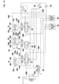
- a hydraulic pump 29 configures a hydraulic source together with a tank 30.
- the hydraulic pump 29 is driven by a prime mover mounted on the deep foundation excavator 1.
- a pilot pump 31 is connected to the hydraulic pump 29, and the pilot pump 31 is driven together with hydraulic pump 29 by the prime mover. Hydraulic oil delivered from the hydraulic pump 29 is selectively supplied via a center bypass-type main line 32 to the raising/lowering cylinder 12, the opening/closing cylinder 18 and the slack adjustment cylinder 26.
- a raising/lowering switching valve 33 is disposed between the hydraulic pump 29 and the raising/lowering cylinder 12 in the main line 32.
- an opening/closing switching valve 34 is disposed between the hydraulic pump 29 and the opening/closing cylinder 18 in the main line 32.
- the raising/lowering switching valve 33 and the opening/closing switching valve 34 each is configured of a hydraulic pilot-type directional control valve of a six-port and three-position, for example.
- the raising/lowering switching valve 33 When the raising/lowering switching valve 33 is switched from a neutral position to a switch position (a), the hydraulic oil delivered from the hydraulic pump 29 is supplied to a rod-side oil chamber in the raising/lowering cylinder 12 to contract the raising/lowering cylinder 12. on the other hand, when the raising/lowering switching valve 33 is switched from the neutral position to a switch position (b), the hydraulic oil delivered from the hydraulic pump 29 is supplied to a bottom-side oil chamber in the raising/lowering cylinder 12 to expand the raising/lowering cylinder 12.
- the opening/closing switching valve 34 When the opening/closing switching valve 34 is switched from a neutral position to a switch position (c), the hydraulic oil delivered from the hydraulic pump 29 is supplied to a rod-side oil chamber in the opening/closing cylinder 18 to contract the opening/closing cylinder 18. On the other hand, when the opening/closing switching valve 34 is switched from the neutral position to a switch position (d), the hydraulic oil delivered from the hydraulic pump 29 is supplied to a bottom-side oil chamber in the opening/closing cylinder 18 to expand the opening/closing cylinder 18.
- a slack adjustment switching valve 35 is disposed between the hydraulic pump 29 and the slack adjustment cylinder 26 in the main line 32.
- the slack adjustment switching valve 35 is configured of a hydraulic pilot-type directional control valve of a six-port and three-position, for example.
- the raising/lowering operation pedal 36, the opening/closing operation lever 39 and the slack operation pedal 42 are arranged in the cab 4 of the deep foundation excavator 1.
- the raising/lowering operation pedal 36 is attached to a pilot operation valve 37 of a pressure reduction-valve type having a pair of pressure reduction valve portions 37A, 37B, and is operated to be depressed to a contraction side or an expansion side.
- a pilot pressure delivered from the pilot pump 31 is supplied via a pilot line 38A to the raising/lowering switching valve 33.
- the raising/lowering switching valve 33 is switched to the switch position (a) to contract the raising/lowering cylinder 12.
- the opening/closing operation lever 39 is attached to a pilot operation valve 40 of a pressure reduction-valve type having a pair of pressure reduction valve portions 40A, 40B.
- the opening/closing operation lever 39 is operated to be tilted to a contraction side or an expansion side by an operator.
- the pilot pressure is supplied via a pilot line 41A to the opening/closing switching valve 34.
- the opening/closing switching valve 34 is switched to the switch position (c) to contract the opening/closing cylinder 18.
- the opening/closing switching valve 34 is switched to the switch position (d) to expand the opening/closing cylinder 18.
- the slack operation pedal 42 is attached to a pilot operation valve 43 of a pressure reduction-valve type having a pair of pressure reduction valve portions 43A, 43B.
- the slack operation pedal 42 is operated to be depressed to a contraction side or an expansion side by an operator.
- the pilot pressure is supplied via a pilot line 44A to the slack adjustment switching valve 35.
- the slack adjustment switching valve 35 is switched to the switch position (e) to contract the slack adjustment cylinder 26.
- the pilot pressure is supplied via a pilot line 44B to the slack adjustment switching valve 35.
- the slack adjustment switching valve 35 is switched to a switch position (f) to expand the slack adjustment cylinder 26.
- the raising/lowering cylinder 12, the opening/closing cylinder 18 and the slack adjustment cylinder 26 are independently operated by the raising/lowering operation pedal 36, the opening/closing operation lever 39 and the slack operation pedal 42 respectively.
- the deep foundation excavator 1 according to the present embodiment has the configuration as described above, and hereinafter, an explanation will be made of the work for excavating the vertical shaft using the deep foundation excavator 1.
- An operator getting in the cab 4 arranges the clamshell bucket 10 over the ground for excavating the vertical shaft in a state of being closed.
- the operator depresses the raising/lowering operation pedal 36 to the contraction side.
- the pilot pressure is supplied via the pilot line 38A to the raising/lowering switching valve 33 to switch the raising/lowering switching valve 33 to the switch position (a) .
- the raising/lowering cylinder 12 is contracted, the first raising/lowering sheave 14 moves toward the second raising/lowering sheave 17 and the first opening/closing sheave 15 moves toward the second opening/closing sheave 20.
- the raising/lowering rope 24 and the opening/closing rope 25 are sent out from the arm 7 and the clamshell bucket 10 lowers.
- the operator continues to perform the depression operation of the raising/lowering operation pedal 36 to the contraction side. Thereby, while the clamshell bucket 10 is held in the landed position, the raising/lowering rope 24 and the opening/closing rope 25 are further sent out. Therefore, as shown in Fig. 6 , the raising/lowering rope 24 and the opening/closing rope 25 start to be slacked.
- the clamshell bucket 10 gets into under the ground from the ground to shovel a lot of sand and earth.
- the operator depresses the slack operation pedal 42 to the expansion side before closing the clamshell bucket 10.
- the pilot pressure is supplied via the pilot line 44B to the slack adjustment switching valve 35 to.switch the slack adjustment switching valve 35 to the switch position (f).
- the slack adjustment cylinder 26 is expanded and the slack adjustment sheave 28 moves to be separated from the second opening/closing sheave 20.
- the raising/lowering rope 24 is slacked, only the slack of the opening/closing rope 25 is removed.
- the operator tilts the opening/closing operation lever 39 to the expansion side.
- the pilot pressure is supplied via the pilot line 41B to the opening/closing switching valve 34 to switch the opening/closing switching valve 34 to the switch position (d) .
- the opening/closing cylinder 18 is expanded and the second opening/closing sheave 20 moves to be separated from the first opening/closing sheave 15.
- the opening/closing rope 25 is pulled up.
- the clamshell bucket 10 will be closed while getting into under the ground by its own weight, and can shovel a lot of sand and earth.
- a force (pulling-up force) acting on the opening/closing rope 25 from the opening/closing cylinder 18 at the time of closing the clamshell bucket 10 is set to be smaller than the weight of the clamshell bucket 10.
- the force acting on the opening/closing rope 25 from the opening/closing cylinder 18 prevents the clamshell bucket 10 from lifting up.
- the raising/lowering rope 24 is in advance slacked so that the clamshell bucket 10 can get into under the ground sufficiently, the slack remains in the raising/lowering rope 24 to some degrees in a state where the clamshell bucket 10 is closed under the ground.
- the operator depresses the raising/lowering operation pedal 36 to the expansion side and depresses the slack operation pedal 42 to the contraction side.
- the pilot pressure is supplied via the pilot line 38B to the raising/lowering switching valve 33 to switch the raising/lowering switching valve 33 to the switch position (b) in response to the operation of the raising/lowering operation pedal 36.
- the pilot pressure is supplied via the pilot line 44A to the slack adjustment switching valve 35 to switch the slack adjustment switching valve 35 to the switch position (e) in response to the operation of the slack operation pedal 42.
- the slack adjustment cylinder 26 is contracted to be back to an initial position, and the slack adjustment sheave 28 moves toward the second opening/closing sheave 20 to slack the opening/closing rope 25.
- the raising/lowering cylinder 12 expands and, the first raising/lowering sheave 14 moves to be separated from the second raising/lowering sheave 17 to pull up the raising/lowering rope 24 and the first opening/closing sheave 15 moves to be separated from the second opening/closing sheave 20 to pull up the opening/closing rope 25.
- the slack adjustment cylinder 26 is caused to contract with a little delay.
- the tension acting on the raising/lowering rope 24 and the tension acting on the opening/closing rope 25 can be uniformed.
- the clamshell bucket 10 is caused to raise to the exterior of the vertical shaft. Thereafter, for example, by revolving the upper revolving structure 3, the clamshell bucket 10 is moved upward of the cargo bed in a dump truck (not shown) . In this state, the operator tilts the opening/closing operation lever 39 to the contraction side. Thereby, the pilot pressure is supplied via the pilot line 41A to the opening/closing switching valve 34 to switch the opening/closing switching valve 34 to the switch position (c) . Accordingly, the opening/closing cylinder 18 is contracted and the second opening/closing sheave 20 moves toward the first opening/closing sheave 15 to pull out the opening/closing rope 25. As a result, the clamshell bucket 10 is opened, enabling the excavated sand and earth to be discharged on the cargo bed of the dump truck.
- the upper revolving structure 3 is caused to revolve to move the clamshell bucket 10 upward of the vertical shaft, and it is possible to excavate the vertical shaft by repeating the above-mentioned work (operation).
- the bucket raising/lowering and opening/closing device 11 in the deep foundation excavator 1 includes:
- the deep foundation excavator 1 is provided with the slack adjustment cylinder 26 that is disposed in the arm 7 and expands and contracts for adjusting the slack of the opening/closing rope 25 and the slack adjustment sheave 28 around which an intermediate portion of the opening/closing rope 25 is wound in a state of being attached on the one end of the slack adjustment cylinder 26 and that moves in a direction of being closer to and being separated from the second opening/closing sheave 20 in response to the expansion/contraction operation of the slack adjustment cylinder 26.
- the raising/lowering rope 24 and the opening/closing rope 25 are caused to slack.
- the clamshell bucket 10 can be made in a state of being capable of getting into under the ground by its own weight.
- the slack of the opening/closing rope 25 is removed by the slack adjustment cylinder 26 and the clamshell bucket 10 is closed by the opening/closing cylinder 18. Accordingly, by closing the clamshell bucket 10 while getting into under the ground, a great number of sand and earth can be shoveled by an excavating movement of one time to enhance the excavating efficiency of sand and earth.
- the clamshell bucket 10 can be lifted up in a state of holding the stable posture. Accordingly, by suppressing the cargo dropping from the clamshell bucket 10, the discharged sand and earth can be safely discharged on the cargo bed of the dump truck or the like. In addition, the lifetime of the raising/lowering rope 24 and the opening/closing rope 25 can be extended.
- the swing link as similar to the bucket raising/lowering device in Patent Document 2 does not need to be attached in the arm. Therefore, the vehicle body height of the deep foundation excavator 1 at the excavating work can be suppressed to be small, and the deep foundation excavator 1 can be applied also to a working site having the height limitation in a site or the like for executing the inverted construction method, for example.
- the raising/lowering cylinder 12, the opening/closing cylinder 18 and the slack adjustment cylinder 26 each are arranged along the longitudinal direction of the arm 7. According to this configuration, the raising/lowering cylinder 12, the opening/closing cylinder 18 and the slack adjustment cylinder 26 can be accommodated compactly in the arm 7 to downsize the working mechanism 5 in the deep foundation excavator 1 as much as possible.
- Fig. 10 shows a second embodiment of the present invention.
- the present embodiment is characterized in that a bucket raising/lowering and opening/closing device is provided with two raising/lowering ropes and two opening/closing ropes.
- components in the second embodiment identical to those in the first embodiment are referred to as identical reference numerals, and the explanation is omitted.
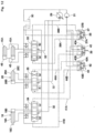
- an additional first raising/lowering sheave 14' composed of a plurality of sheaves configuring a bucket raising/lowering and opening/closing device 11 is rotatably supported together with the first raising/lowering sheave 14 on the first shaft member 13.
- An additional first opening/closing sheave 15' composed of a plurality of sheaves is rotatably supported together with the first opening/closing sheave 15 on the first shaft member 13.
- An additional second raising/lowering sheave 17' composed of a plurality of sheaves is rotatably supported together with the second raising/lowering sheave 17 on the second shaft member 16 in a state of being separated from the additional first raising/lowering sheave 14' in the expansion/contraction direction of the raising/lowering cylinder 12.
- An additional second opening/closing sheave 20' composed of a plurality of sheaves is rotatably supported together with the second opening/closing sheave 20 on the third shaft member 19 in a state of being separated from the additional first opening/closing sheave 15' in the expansion/contraction direction of the raising/lowering cylinder 12.
- An additional raising/lowering guide sheave 22' and an additional opening/closing guide sheave 23' each are attached on the tip end of the arm 7.
- An additional raising/lowering rope 24' is a second raising/lowering rope paired to the raising/lowering rope 24.
- One end 24A' of the additional raising/lowering rope 24' is attached in the arm 7.
- the other end (not shown) of the additional raising/lowering rope 24' extends downward from the additional raising/lowering guide sheave 22' and is attached on the bucket support portion 10A of the clamshell bucket 10.
- An intermediate portion 24B' of the additional raising/lowering rope 24' is wound around the additional first raising/lowering sheave 14' and the additional second raising/lowering sheave 17' alternately.
- An additional opening/closing rope 25' is a second opening/closing rope paired to the opening/closing rope 25.
- One end 25A' (not shown) of the additional opening/closing rope 25' is attached on the arm 7.
- the other end of the additional opening/closing rope 25' extends downward from the additional opening/closing guide sheave 23' and is attached on the bucket support portion 10A of the clamshell bucket 10.
- An intermediate portion 25B' of the additional opening/closing rope 25' is wound around the additional first opening/closing sheave 15' and the additional second opening/closing sheave 20' alternately.
- the clamshell bucket 10 is supported by two raising/lowering ropes composed of the raising/lowering rope 24 and the additional raising/lowering rope 24', and two opening/closing ropes composed of the opening/closing rope 25 and the additional opening/closing rope 25'.
- a total of the four ropes 24, 24', 25, 25' move in synchronization with the expansion/contraction movement of the raising/lowering cylinder 12 to raise or lower the clamshell bucket 10.
- An additional slack adjustment sheave 28' is rotatably supported together with the slack adjustment sheave 28 on the fifth shaft member 27 in a state of being separated from the additional second opening/closing sheave 20' in the expansion/contraction direction of the raising/lowering cylinder 12.
- One end 25A' of the additional opening/closing rope 25' is wound around the additional slack adjustment sheave 28'.
- the slack adjustment sheave 28 and the additional slack adjustment sheave 28' move in synchronization with the expansion/contraction movement of the slack adjustment cylinder 26 to adjust the slack of the opening/closing rope 25 and the slack of the additional opening/closing rope 25'simultaneously.
- the clamshell bucket 10 is supported by the two raising/lowering ropes composed of the raising/lowering rope 24 and the additional raising/lowering rope 24', and the two opening/closing ropes composed of the opening/closing rope 25 and the additional opening/closing rope 25'.
- the second embodiment is not particularly different in a basic function from the first embodiment.
- the clamshell bucket 10 is supported by a total of the four ropes 24, 24', 25, 25' and therefore, the stability of the clamshell bucket 10 at the raising/lowering can be enhanced.
- the bucket raising/lowering and opening/closing device 11 can be configured to meet the objects of extending the lifetime of each of the ropes 24, 24', 25, 25' and enhancing the maintenance characteristics by thinning down each of the ropes 24, 24', 25, 25'.
- Fig. 11 and Fig. 12 show a third embodiment of the present invention.
- the present embodiment is characterized in that a raising/lowering cylinder in a bucket raising/lowering and opening/closing device comprises two raising/lowering cylinders.
- components in the third embodiment identical to those in the first embodiment are referred to as identical reference numerals, and the explanation is omitted.
- two raising/lowering cylinders 45, 46 configuring a bucket raising/lowering and opening/closing device 11 each are arranged in the arm 7 along the longitudinal direction of the arm 7.
- the two raising/lowering cylinders 45, 46 each have an outer diameter dimension set to be smaller than the raising/lowering cylinder 12 used in the first embodiment.
- the first shaft member 13 is attached on a rod 45A of one raising/lowering cylinder 45 and a rod 46A of the other raising/lowering cylinder 46.
- the two raising/lowering cylinders 45, 46 are connected via the main line 32 in parallel to the hydraulic pump 29. Accordingly, when the raising/lowering operation pedal 36 is depressed to the expansion side, the pilot pressure is supplied via the pilot line 38B to the raising/lowering switching valve 33 to switch the raising/lowering switching valve 33 to the switch position (b). Thereby, the hydraulic oil is simultaneously supplied to bottom-side oil chambers of the raising/lowering cylinders 45, 46 to expand the raising/lowering cylinders 45, 46 in synchronization. In addition, when the raising/lowering operation pedal 36 is depressed to the contraction side, the pilot pressure is supplied via the pilot line 38A to the raising/lowering switching valve 33 to switch the raising/lowering switching valve 33 to the switch position (a). Thereby, the hydraulic oil is simultaneously supplied to rod-side oil chambers of the raising/lowering cylinders 45, 46 to contract the raising/lowering cylinders 45, 46 in synchronization.
- the deep foundation excavator according to the third embodiment is provided with the two raising/lowering cylinders 45, 46, and the third embodiment is not particularly different in a basic function from the first embodiment.
- the third embodiment in a case where an equipment accommodation space within the arm 7 is narrow, even in a case where it is difficult to layout the single raising/lowering cylinder 12 with a large outer diameter dimension within the arm 7, use of the two raising/lowering cylinders 45, 46 smaller in an outer diameter dimension than the raising/lowering cylinder 12 enables the layout within the arm 7.
- the first embodiment shows a case of operating the raising/lowering cylinder 12 by the depression operation of the raising/lowering operation pedal 36, as an example.
- the raising/lowering cylinder 12 maybe operated by a tilting operation of a raising/lowering operation lever.
- the opening/closing cylinder 18 may be operated by an opening/closing operation pedal in place of the opening/closing operation lever 39
- the slack adjustment cylinder 26 may be operated by a slack operation lever in place of the slack operation pedal 42.
- the first embodiment shows a case where the hydraulic oil delivered from the single hydraulic pump 29 is selectively supplied to the raising/lowering cylinder 12, the opening/closing cylinder 18 and the slack adjustment cylinder 26.
- the present invention is not limited thereto, but for example, three hydraulic pumps (triple pump) simultaneously driven by a prime mover may be used, wherein the hydraulic oil from the three hydraulic pumps may be supplied to a raising/lowering cylinder, an opening/closing cylinder and a slack adjustment cylinder individually.
- Fig. 13 and Fig. 14 show a fourth embodiment of the present invention.
- the present embodiment is characterized in that when it is detected that a tension acting on an opening/closing rope is equal to or less than a predetermined value, an operation target of an opening/closing operation tool is switched to a slack adjustment cylinder from an opening/closing cylinder.
- components in the fourth embodiment identical to those in the first embodiment are referred to as identical reference numerals, and the explanation is omitted.
- the slack operation pedal 42 is operated to remove the slack of the opening/closing rope 25.
- the opening/closing operation lever 39 in a state of in advance removing the slack of the opening/closing rope 25, the clamshell bucket 10 can quickly be closed to enhance the workability of the excavating work.
- a bucket raising/lowering and opening/closing device 51 according to the fourth embodiment as similar to the bucket raising/lowering and opening/closing device 11 according to the first embodiment, includes the raising/lowering cylinder 12, the first raising/lowering sheave 14, the first opening/closing sheave 15, the second raising/lowering sheave 17, the opening/closing cylinder 18, the second opening/closing sheave 20, the raising/lowering rope 24, the opening/closing rope 25, the slack adjustment cylinder 26, and the slack adjustment sheave 28.
- the bucket raising/lowering and opening/closing device 51 according to the fourth embodiment is different, in a point where a detecting device 52 configured to detect the slack of the opening/closing rope 25 is disposed, from the first embodiment.
- the detecting device 52 is disposed between the arm 7 and the one end 25A of the opening/closing rope 25.
- the detecting device 52 is configured of a spring member 53 and a detector 54.
- the spring member 53 is formed as a compression spring tightly held between the arm 7 and the one end 25A of the opening/closing rope 25.
- the spring member 53 is set to have load characteristics to be compressed in a state where the clamshell bucket 10 is suspended to the arm 7. That is, the spring member 53 contracts by the weight of the clamshell bucket 10.
- the opening/closing rope 25 is slacked by the clamshell bucket 10 being landed, the spring member 53 expands.
- the detector 54 detects the slack of the opening/closing rope 25, that is, a free state of the spring member 53.
- the detector 54 is formed as a contact type sensor (switch) that switches between an on state and an off state in response to an inclination of a lever 54A.
- a non-contact type sensor that switches between an on state and an off state by a change of a magnetic force or an optical source may be used as a detector.
- the detector 54 turns off.
- the opening/closing rope 25 is slacked and the one end 25A of the opening/closing rope 25 pushes the lever 54A by the spring member 53, the lever 54A is inclined to switch the detector 54 to the on state. Since the detector 54 is switched to the on state when the tension acting on the opening/closing rope 25 becomes equal to or less than a predetermined value, power is fed to an electromagnetic pilot portion 63A of an after-mentioned cylinder switching valve 63 based upon a detection signal at this time.
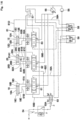
- the upper revolving structure 3 includes a main pump 55, a pilot pump 56 and a hydraulic oil tank 57.
- the cab 4 is provided with a raising/lowering operation tool 58 and an opening/closing operation tool 59 each composed of an operation lever, an operation pedal and the like.
- the raising/lowering operation tool 58 is connected via a first pilot line 58A and a second pilot line 58B to a raising/lowering switching valve 60.
- This raising/lowering switching valve 60 has three positions of a closing position for stopping the expansion/contraction movement of the raising/lowering cylinder 12, an expansion position for expanding the rod 12C of the raising/lowering cylinder 12, and a contraction position for contracting the rod 12C of the raising/lowering cylinder 12.
- the raising/lowering switching valve 60 is operated to be switched to the three positions by the raising/lowering operation tool 58.
- the raising/lowering switching valve 60 is connected via a bottom-side line 60A to a bottom-side oil chamber 12D in the raising/lowering cylinder 12 and is connected via a rod-side line 60B to a rod-side oil chamber 12E in the raising/lowering cylinder 12.
- an additional pilot line 64E for supplying a pilot pressure to an after-mentioned pilot operation check valve 64B is connected to the first pilot line 58A for switching the raising/lowering switching valve 60 to the expansion position.
- the opening/closing operation tool 59 is connected via a first pilot line 59A and a second pilot line 59B to an opening/closing switching valve 61.
- This opening/closing switching valve 61 has, as similar to the raising/lowering switching valve 60, three positions of a closing position for stopping the expansion/contraction movement of the opening/closing cylinder 18, an expansion position for expanding the rod 18C of the opening/closing cylinder 18, and a contraction position for contracting the rod 18C of the opening/closing cylinder 18.
- the opening/closing switching valve 61 is operated to be switched to the three positions by the opening/closing operation tool 59.
- the opening/closing switching valve 61 is connected via a bottom-side line 61A to a bottom-side oil chamber 18D in the opening/closing cylinder 18 and is connected via a rod-side line 61B to a rod-side oil chamber 18E in the opening/closing cylinder 18.
- an after-mentioned cylinder switching valve 63 is connected to the second pilot line 59B for switching the opening/closing switching valve 61 to the expansion side of the rod 18C in the opening/closing cylinder 18.
- a slack removal switching valve 62 has two positions of a closing position for stopping the expansion/contraction movement of the slack adjustment cylinder 26 and an expansion position for expanding the rod 26C of the slack adjustment cylinder 26.
- the slack removal switching valve 62 is operated to be switched to the two positions by the opening/closing operation tool 59 or the like.
- the slack removal switching valve 62 is connected via a bottom-side line 62A to a bottom-side oil chamber 26D in the slack adjustment cylinder 26 and is connected via a rod-side line 62B to a rod-side oil chamber 26E in the slack adjustment cylinder 26.
- the slack removal switching valve 62 is provided with a pilot line 62C to switch the slack removal switching valve 62 to the expansion position.
- the pilot line 62C of the slack removal switching valve 62 is connected via the cylinder switching valve 63 to the hydraulic oil tank 57 or the opening/closing operation tool 59.
- the cylinder switching valve 63 is disposed along the path of the second pilot line 59B of the opening/closing operation tool 59 and the pilot line 62C of the slack removal switching valve 62.
- the cylinder switching valve 63 switches, when the detector 54 in the detecting device 52 detects that the tension acting on the opening/closing rope 25 is equal to or less than a predetermined value, the operation target of the opening/closing operation tool 59 from the opening/closing cylinder 18 to the slack adjustment cylinder 26.
- the cylinder switching valve 63 has two positions of a switch position (g) in which the pilot pressure (hydraulic oil) from the opening/closing operation tool 59 can be supplied to the opening/closing switching valve 61 and a switch position (h) in which the pilot pressure from the opening/closing operation tool 59 can be supplied to the slack removal switching valve 62.
- a switch position (g) in which the pilot pressure (hydraulic oil) from the opening/closing operation tool 59 can be supplied to the opening/closing switching valve 61
- a switch position (h) in which the pilot pressure from the opening/closing operation tool 59 can be supplied to the slack removal switching valve 62.
- an electromagnetic pilot portion 63A is connected to the detector 54 in the detecting device 52. Thereby, the cylinder switching valve 63 is switched to the switch position (h) by the power feeding to the electromagnetic pilot portion 63A when the detector 54 turns on.
- a cylinder contraction device 64 contracts the rod 26C in the slack adjustment cylinder 26 when the raising/lowering operation tool 58 is operated to a raising side of raising the clamshell bucket 10.
- the cylinder contraction device 64 contracts the rod 26C in the slack adjustment cylinder 26.
- the cylinder contraction device 64 includes a discharge liquid line 64A for connection between the bottom-side oil chamber 26D in the slack adjustment cylinder 26 and the hydraulic oil tank 57, a pilot operation check valve 64B and a throttle 64C arranged in the discharge liquid line 64A, a check valve 64D disposed in the bottom-side line 62A in the slack removal switching valve 62 and an additional pilot line 64E for connection between the first pilot line 58A in the raising/lowering operation tool 58 and the pilot operation check valve 64B.
- the pilot operation check valve 64B is usually closed to block the discharge liquid line 64A.
- the pilot operation check valve 64B is opened when the pilot pressure is supplied from the additional pilot line 64E to cause the hydraulic oil to flow in the discharge liquid line 64A.
- the throttle 64C restricts a speed by which the rod 26C in the slack adjustment cylinder 26 contracts by throttling a flow amount of the hydraulic oil.
- the check valve 64D prevents the hydraulic oil in the bottom-side oil chamber 26D from flowing back to the slack removal switching valve 62-side.
- the additional pilot line 64E supplies the pilot pressure toward the pilot operation check valve 64B when the raising/lowering operation tool 58 is operated to the raising side to raise the clamshell bucket 10.
- the hydraulic oil of the bottom-side oil chamber 26D in the slack adjustment cylinder 26 is discharged via the discharge liquid line 64A and the like to the hydraulic oil tank 57. That is, when the raising/lowering operation tool 58 is operated to the raising side to raise the clamshell bucket 10, in a case where the rod 26C in the slack adjustment cylinder 26 is expanded, the rod 26C is gradually contracted to become in the most contracted state.
- An operator who gets in the cab 4 arranges the clamshell bucket 10 over the excavating position in a state where the clamshell bucket 10 is closed.
- the detector 54 of the detecting device 52 is in an off state.
- the raising/lowering operation tool 58 is operated to the lowering side.
- the raising/lowering switching valve 60 is switched to the contraction position by the pilot pressure from the second pilot line 58B to contract the raising/lowering cylinder 12.
- each sheave of the first raising/lowering sheave 14 moves to each sheave side of the second raising/lowering sheave 17 and each sheave of the first opening/closing sheave 15 moves to each sheave side of the second opening/closing sheave 20. Therefore, the raising/lowering rope 24 and the opening/closing rope 25 are sent out from the arm 7 to lower the clamshell bucket 10.
- the opening/closing operation tool 59 is operated to the closing side.
- the detector 54 of the detecting device 52 detects the slack of the spring member 53 to feed power to the electromagnetic pilot portion 63A of the cylinder switching valve 63.
- the cylinder switching valve 63 is switched to the switch position (h) in which the pilot pressure from the opening/closing operation tool 59 can be supplied to the slack removal switching valve 62.
- the slack adjustment cylinder 26 automatically removes the slack of the opening/closing rope 25 by expanding the rod 26C.
- the cylinder switching valve 63 is automatically switched back to the switch position (g).
- the raising/lowering operation tool 58 is operated to the raising side to raise the clamshell bucket 10.
- the opening/closing rope 25 is in a tensioning state where the slack is removed by the slack adjustment cylinder 26, when the clamshell bucket 10 is raised in this state, the clamshell bucket 10 results in being suspended by the opening/closing rope 25 only.
- part of the pilot pressure to be supplied via the first pilot line 58A to the raising/lowering switching valve 60 is supplied via the additional pilot line 64E to the pilot operation check valve 64B of the cylinder contraction device 64.
- the pilot operation check valve 64B is opened to discharge the hydraulic oil in the bottom-side oil chamber 26D of the slack adjustment cylinder 26 to the hydraulic oil tank 57-side.
- the slack adjustment cylinder 26 contracts the rod 26C.
- the throttle 64C throttles the flow amount of the hydraulic oil to flow out from the bottom-side oil chamber 26D, thus making it possible to gradually contract the rod 26C of the slack adjustment cylinder 26.
- the cylinder contraction device 64 contracts, at the time of raising the clamshell bucket 10, the rod 26C of the slack adjustment cylinder 26 together with the raising operation, thereby making it possible to raise the clamshell bucket 10 in the stable state while tailoring the tensions of two ropes of the raising/lowering rope 24 and the opening/closing rope 25.
- the cylinder contraction device 64 gradually contracts the rod 26C of the slack adjustment cylinder 26 so that the tension of the opening/closing rope 25 does not become smaller than the tension of the raising/lowering rope 24. Thereby, the clamshell bucket 10 can be raised in the stable state.
- the raising/lowering operation tool 58 is successively operated to expand the raising/lowering cylinder 12 and raise the clamshell bucket 10.
- the clamshell bucket 10 moves upward of a dump truck (not shown) or the like.
- the opening/closing operation tool 59 By operating the opening/closing operation tool 59 to the opening side and slacking the opening/closing rope 25, the clamshell bucket 10 is opened to discharge the soil on the cargo bed of the dump truck.
- the slack adjustment cylinder 26 is in the most contracted state, even when the opening/closing rope 25 is slacked, the clamshell bucket 10 can be held by the raising/lowering rope 24.
- the clamshell bucket 10 After sand and earth is loaded on the cargo bed of the dump truck, the clamshell bucket 10 is moved back over the vertical shaft, and by repeating the above-mentioned work (operation), the deep foundation excavator 1 can excavate the vertical shaft.
- the bucket raising/lowering and opening/closing device 51 includes the raising/lowering operation tool 58 for operating the raising/lowering cylinder 12, the opening/closing operation tool 59 for operating the opening/closing cylinder 18, the detector 54 in the detecting device 52 for detecting whether or not the tension acting on the opening/closing rope 25 is equal to or less than the predetermined value, the cylinder switching valve 63 for switching the operation target of the opening/closing operation tool 59 from the opening/closing cylinder 18 to the slack adjustment cylinder 26 when the detector 54 detects the tension acting on the opening/closing rope 25 is equal to or less than the predetermined value, and the cylinder contraction device 64 for contracting the slack adjustment cylinder 26.
- the tensions acting on the raising/lowering rope 24 and the opening/closing rope 25 can be automatically tailored in accordance with the operation condition, and therefore, the dynamic lift off work from the excavation and the soil discharging work to the dump truck can be stably carried out.
- the excavating work by the clamshell bucket 10 can be easily and accurately operated regardless of the level of skill.
- the tension is caused to act equally on the raising/lowering rope 24 and the opening/closing rope 25, it is possible to improve the durability on each of the rope 24 and the rope 25.
- the stroke of the raising/lowering cylinder 12 can be shortened to downsize the bucket raising/lowering and opening/closing device 51. Thereby, the workability in the narrow working site can improve.
- the raising/lowering cylinder 12 and the opening/closing cylinder 18, and the slack adjustment cylinder 26 are arranged in parallel in the lateral direction of the arm 7, and also in this respect, the bucket raising/lowering and opening/closing device 51 can be downsized.
- Fig. 15 shows a fifth embodiment of the present invention.
- the present embodiment is characterized in that a throttle of a cylinder contraction device is provided with an adjustment portion for adjusting a flow amount of hydraulic oil.
- components in the fifth embodiment identical to those in the fourth embodiment are referred to as identical reference numerals, and the explanation is omitted.
- a cylinder contraction device 71 according to the fifth embodiment includes, as similar to the cylinder contraction device 64 according to the fourth embodiment, a discharge liquid line 71A, a pilot operation check valve 71B, a throttle 71C, a check valve 71D and an additional pilot line 71E.
- the cylinder contraction device 71 according to the fifth embodiment is different in a point where the throttle 71C is provided with an adjustment portion 71C1 from the cylinder contraction device 64 according to the fourth embodiment.
- the adjustment portion 71C1 of the throttle 71C adjusts, for example, an opening area to adjust the flow amount of the hydraulic oil for communication.
- the adjustment portion 71C1 can adjust the time until the rod 26C in the slack adjustment cylinder 26 is contracted to the maximum.
- the movement of the slack adjustment cylinder 26 can be adjusted in accordance with the hardness of sand and earth to be excavated or the preference of an operator to enhance the working efficiency.
- Fig. 16 shows a sixth embodiment of the present invention.
- the present embodiment is characterized in that a cylinder contraction device is provided with a forced switch pilot line for switching a slack removal switching valve so that when a raising/lowering operation tool is operated to a raising side to raise a clamshell bucket, hydraulic oil is supplied to a rod-side oil chamber in a slack removal cylinder.
- a forced switch pilot line for switching a slack removal switching valve so that when a raising/lowering operation tool is operated to a raising side to raise a clamshell bucket, hydraulic oil is supplied to a rod-side oil chamber in a slack removal cylinder.
- a cylinder contraction device 81 includes a throttle 81A with an adjustment portion 81A1 disposed in a rod-side line 82B of a slack removal switching valve 82, a check valve 81C disposed in a bypass line 81B for bypassing the throttle 81A, and a forced switch pilot line 81D for connection between the first pilot line 58A of the raising/lowering operation tool 58 and the slack removal switching valve 82.
- the slack removal switching valve 82 is provided with a bottom-side line 82A and a pilot line 82C.
- the throttle 81A restricts a speed by which the rod 26C in the slack adjustment cylinder 26 contracts by throttling the flow amount of the hydraulic oil.
- the adjustment portion 81A1 can adjust the time until the rod 26C in the slack adjustment cylinder 26 is contracted to the maximum.
- the check valve 81C allows the hydraulic oil in the rod-side oil chamber 26E to flow to the slack removal switching valve 82-side and blocks the reverse flow. That is, in a case of contracting the rod 26C in the slack adjustment cylinder 26, since the flow amount of the hydraulic oil is throttled by the throttle 81A, the rod 26C is gradually contracted.
- the forced switch pilot line 81D switches the slack removal switching valve 82 so that when the raising/lowering operation tool 58 is operated to the raising side to raise the clamshell bucket 10, the hydraulic oil is supplied to the rod-side oil chamber 26E in the slack adjustment cylinder 26.
- the forced switch pilot line 81D switches the slack removal switching valve 82 to the contraction position using part of the pilot pressure supplied via the first pilot line 58A to the raising/lowering switching valve 60.
- the slack removal switching valve 82 supplies the hydraulic oil via the rod-side line 82B to the rod-side oil chamber 26E in the slack adjustment cylinder 26.
- the throttle 81A restricts a speed by which the rod 26C in the slack adjustment cylinder 26 contracts by throttling the flow amount of the hydraulic oil.
- an adjustment portion 81A11 can adjust the time until the rod 26C in the slack adjustment cylinder 26 is contracted to the maximum.
- Fig. 1 shows a state of carrying out the excavating work while holding the arm 7 in the horizontal posture.
- the present invention is not limited thereto, but an excavating work of a vertical shaft may be carried out in another posture of the arm7, such as a vertical posture or an inclined posture. This configuration can be applied similarly to the other embodiments each.
- the first embodiment is configured so that the clamshell bucket 10 lowers at the time of contracting the rod 12C in the raising/lowering cylinder 12 and raises at the time of expanding the rod 12C in the raising/lowering cylinder 12.
- the present invention is not limited thereto, but may be configured so that the clamshell bucket 10 raises at the time of contracting the rod 12C in the raising/lowering cylinder 12 and lowers at the time of expanding the rod 12C in the raising/lowering cylinder 12.
- the expansion/contraction movement of the opening/closing cylinder 18 and the opening/closing movement of the clamshell bucket 10 may be reversed to each other.
- the expansion/contraction movement of the slack adjustment cylinder 26 and the slack removal movement by the slack adjustment sheave 28 may be reversed to each other.
- the present invention is not limited thereto, but may be configured so that, for example, the arm 7 is formed as the long square cylindrical body and the bucket raising/lowering and opening/closing device 11 is disposed inside the arm 7. This configuration can be applied similarly to the other embodiments each.
Landscapes
- Engineering & Computer Science (AREA)
- Mining & Mineral Resources (AREA)
- Civil Engineering (AREA)
- General Engineering & Computer Science (AREA)
- Structural Engineering (AREA)
- Mechanical Engineering (AREA)
- Physics & Mathematics (AREA)
- Fluid Mechanics (AREA)
- Load-Engaging Elements For Cranes (AREA)
- Operation Control Of Excavators (AREA)
Applications Claiming Priority (3)
| Application Number | Priority Date | Filing Date | Title |
|---|---|---|---|
| JP2020063331 | 2020-03-31 | ||
| JP2020063338 | 2020-03-31 | ||
| PCT/JP2021/009328 WO2021199965A1 (ja) | 2020-03-31 | 2021-03-09 | 深礎掘削機 |
Publications (2)
| Publication Number | Publication Date |
|---|---|
| EP4130392A1 true EP4130392A1 (de) | 2023-02-08 |
| EP4130392A4 EP4130392A4 (de) | 2024-04-17 |
Family
ID=77928567
Family Applications (1)
| Application Number | Title | Priority Date | Filing Date |
|---|---|---|---|
| EP21781835.0A Pending EP4130392A4 (de) | 2020-03-31 | 2021-03-09 | Tiefgründungsbagger |
Country Status (6)
| Country | Link |
|---|---|
| US (1) | US12435486B2 (de) |
| EP (1) | EP4130392A4 (de) |
| JP (1) | JP7166487B2 (de) |
| KR (1) | KR102560265B1 (de) |
| CN (1) | CN114222842B (de) |
| WO (1) | WO2021199965A1 (de) |
Families Citing this family (5)
| Publication number | Priority date | Publication date | Assignee | Title |
|---|---|---|---|---|
| KR102560265B1 (ko) * | 2020-03-31 | 2023-07-28 | 히다찌 겐끼 가부시키가이샤 | 심초 굴착기 |
| WO2023145819A1 (ja) * | 2022-01-27 | 2023-08-03 | 日立建機株式会社 | 深礎掘削機 |
| EP4624674A1 (de) * | 2023-01-20 | 2025-10-01 | Hitachi Construction Machinery Co., Ltd. | Tiefgründungsbagger |
| JP7467732B1 (ja) | 2023-05-30 | 2024-04-15 | 大成建設株式会社 | 搬送装置 |
| WO2025205250A1 (ja) * | 2024-03-26 | 2025-10-02 | 日立建機株式会社 | 深礎掘削機 |
Family Cites Families (22)
| Publication number | Priority date | Publication date | Assignee | Title |
|---|---|---|---|---|
| US3157288A (en) * | 1960-12-08 | 1964-11-17 | Wieger Ernst | Multi-purpose earth moving machine |
| US3303590A (en) * | 1963-07-29 | 1967-02-14 | Grospas Pierre | Gravity-closing scoop |
| JPS537043B2 (de) * | 1974-06-06 | 1978-03-14 | ||
| JPS52108602A (en) | 1976-03-09 | 1977-09-12 | Minami Tetsukoushiyo Kk | Clamshell attachment for shovel |
| JPS52131602A (en) * | 1976-04-28 | 1977-11-04 | Hitachi Construction Machinery | Rope type clammshell bucket operating device in hydraulic shovel |
| CA1120076A (en) * | 1978-07-28 | 1982-03-16 | Ryutaro Yoritomi | Excavator with a clamshell bucket having magnified vertical stroke |
| JPS56159434A (en) | 1980-05-12 | 1981-12-08 | Ryutaro Yoritomi | Excavating machine with clamshell backet |
| JPS5736373A (ja) | 1980-08-14 | 1982-02-27 | Tokyo Electric Co Ltd | Raberuokuriseigyosochi |
| JPS58176157A (ja) * | 1982-04-09 | 1983-10-15 | ダイセル化学工業株式会社 | 高粘度生コンクリ−ト |
| JPS5917977Y2 (ja) | 1982-06-24 | 1984-05-24 | 株式会社南鉄工所 | シヨベル用クラムシエルアタツチメント |
| JPH09286588A (ja) * | 1996-02-19 | 1997-11-04 | Minami Tekkosho:Kk | 開閉式作業具 |
| DE29917595U1 (de) * | 1999-10-06 | 2000-11-23 | Hölscher Wasserbau GmbH & Co KG, 49733 Haren | Bohrgreifer |
| JP3866962B2 (ja) | 2001-11-12 | 2007-01-10 | コベルコ建機株式会社 | 深穴作業機 |
| CN104162200B (zh) | 2006-02-09 | 2018-03-27 | 德卡产品有限公司 | 外围系统 |
| CN100567663C (zh) * | 2007-04-19 | 2009-12-09 | 安徽省六安恒源机械有限公司 | 移动液压抓斗式清污机 |
| BR112012003698B1 (pt) | 2009-08-20 | 2018-12-26 | Bayer Intellectual Property Gmbh | Compostos derivados de 3-[1-(3-haloalquil)-triazolil]-fenil-sulfeto, processos para preparação de compostos, compostos intermediários, composições, composiçõesagroquímicas e uso dos compostos e composições como acaricidas e inseticidas |
| JP5873840B2 (ja) | 2013-06-14 | 2016-03-01 | 日立建機株式会社 | 多段アームの油圧装置および深掘り掘削機 |
| CN104018541B (zh) * | 2014-06-18 | 2016-07-06 | 上海工程技术大学 | 一种重力式液压破碎锤 |
| CN210193255U (zh) * | 2019-07-26 | 2020-03-27 | 青岛嘉恒建设集团有限公司 | 一种建筑机械起重臂 |
| TWI780579B (zh) | 2020-02-03 | 2022-10-11 | 美商應用材料股份有限公司 | 具有整合化氮化鋁晶種或波導層的超導奈米線單光子偵測器 |
| KR102560265B1 (ko) * | 2020-03-31 | 2023-07-28 | 히다찌 겐끼 가부시키가이샤 | 심초 굴착기 |
| JP2024159434A (ja) | 2023-04-28 | 2024-11-08 | 学校法人静岡理工科大学 | 芳香族、脂肪族又は脂環式過カルボン酸化合物の製造方法 |
-
2021
- 2021-03-09 KR KR1020227004039A patent/KR102560265B1/ko active Active
- 2021-03-09 EP EP21781835.0A patent/EP4130392A4/de active Pending
- 2021-03-09 CN CN202180004920.9A patent/CN114222842B/zh active Active
- 2021-03-09 JP JP2022511731A patent/JP7166487B2/ja active Active
- 2021-03-09 WO PCT/JP2021/009328 patent/WO2021199965A1/ja not_active Ceased
- 2021-03-09 US US17/633,979 patent/US12435486B2/en active Active
Also Published As
| Publication number | Publication date |
|---|---|
| JPWO2021199965A1 (de) | 2021-10-07 |
| KR20220028122A (ko) | 2022-03-08 |
| US20220267984A1 (en) | 2022-08-25 |
| EP4130392A4 (de) | 2024-04-17 |
| CN114222842A (zh) | 2022-03-22 |
| JP7166487B2 (ja) | 2022-11-07 |
| WO2021199965A1 (ja) | 2021-10-07 |
| US12435486B2 (en) | 2025-10-07 |
| CN114222842B (zh) | 2023-05-09 |
| KR102560265B1 (ko) | 2023-07-28 |
Similar Documents
| Publication | Publication Date | Title |
|---|---|---|
| US12435486B2 (en) | Deep foundation excavator | |
| JP5238181B2 (ja) | 油圧ショベル | |
| CN102644304B (zh) | 深挖挖掘机 | |
| JP7166308B2 (ja) | 深礎掘削機 | |
| CA1132101A (en) | Excavator having telescopic arm assembly | |
| JP7143775B2 (ja) | 建設機械 | |
| JP2002173947A (ja) | 掘削機 | |
| JP2019157544A (ja) | 伸縮アームを有する作業機械 | |
| KR101684710B1 (ko) | 건설기계용 카운터웨이트 탈장착 장치 | |
| JP2832452B2 (ja) | 縦穴掘削機におけるケリーバーの押込み力調整装置 | |
| JP2024118985A (ja) | 深礎掘削機 | |
| JP5320003B2 (ja) | 作業機械の油圧制御装置 | |
| JP4367728B2 (ja) | 建設機械におけるブームシリンダ制御装置 | |
| WO2025205250A1 (ja) | 深礎掘削機 | |
| JP2005188157A (ja) | 油圧ショベルのバケット回動角調整装置 | |
| KR200397109Y1 (ko) | 연장 가능한 붐을 가지는 스키드 로더 | |
| JPH05255946A (ja) | 表面掘削ショベルと地表物質を掘削する方法 | |
| JP7640963B2 (ja) | 建設機械 | |
| JP3570826B2 (ja) | 竪孔掘削機 | |
| JPH09217349A (ja) | 作業機のリーダ | |
| JPH09242716A (ja) | 油圧シリンダ装置 | |
| JP2023006130A (ja) | 深礎掘削機 | |
| JP2003063774A (ja) | 高揚程揚重車両の制御装置 | |
| KR102011465B1 (ko) | 건설장비용 변속장치 및 이를 포함하는 건설장비 | |
| JP2024171262A (ja) | 作業機械 |
Legal Events
| Date | Code | Title | Description |
|---|---|---|---|
| STAA | Information on the status of an ep patent application or granted ep patent |
Free format text: STATUS: THE INTERNATIONAL PUBLICATION HAS BEEN MADE |
|
| PUAI | Public reference made under article 153(3) epc to a published international application that has entered the european phase |
Free format text: ORIGINAL CODE: 0009012 |
|
| STAA | Information on the status of an ep patent application or granted ep patent |
Free format text: STATUS: REQUEST FOR EXAMINATION WAS MADE |
|
| 17P | Request for examination filed |
Effective date: 20220329 |
|
| AK | Designated contracting states |
Kind code of ref document: A1 Designated state(s): AL AT BE BG CH CY CZ DE DK EE ES FI FR GB GR HR HU IE IS IT LI LT LU LV MC MK MT NL NO PL PT RO RS SE SI SK SM TR |
|
| DAV | Request for validation of the european patent (deleted) | ||
| DAX | Request for extension of the european patent (deleted) | ||
| A4 | Supplementary search report drawn up and despatched |
Effective date: 20240319 |
|
| RIC1 | Information provided on ipc code assigned before grant |
Ipc: E02F 9/22 20060101ALI20240313BHEP Ipc: E02F 9/14 20060101ALI20240313BHEP Ipc: E02F 3/47 20060101ALI20240313BHEP Ipc: E02F 3/413 20060101AFI20240313BHEP |