EP4130407B1 - Wc mit spezifischer schüsselinnenform - Google Patents
Wc mit spezifischer schüsselinnenform Download PDFInfo
- Publication number
- EP4130407B1 EP4130407B1 EP21189636.0A EP21189636A EP4130407B1 EP 4130407 B1 EP4130407 B1 EP 4130407B1 EP 21189636 A EP21189636 A EP 21189636A EP 4130407 B1 EP4130407 B1 EP 4130407B1
- Authority
- EP
- European Patent Office
- Prior art keywords
- flow path
- bowl
- edge
- inflow step
- opening
- Prior art date
- Legal status (The legal status is an assumption and is not a legal conclusion. Google has not performed a legal analysis and makes no representation as to the accuracy of the status listed.)
- Active
Links
Images




Classifications
-
- E—FIXED CONSTRUCTIONS
- E03—WATER SUPPLY; SEWERAGE
- E03D—WATER-CLOSETS OR URINALS WITH FLUSHING DEVICES; FLUSHING VALVES THEREFOR
- E03D11/00—Other component parts of water-closets, e.g. noise-reducing means in the flushing system, flushing pipes mounted in the bowl, seals for the bowl outlet, devices preventing overflow of the bowl contents; devices forming a water seal in the bowl after flushing, devices eliminating obstructions in the bowl outlet or preventing backflow of water and excrements from the waterpipe
- E03D11/02—Water-closet bowls ; Bowls with a double odour seal optionally with provisions for a good siphonic action; siphons as part of the bowl
- E03D11/08—Bowls with means producing a flushing water swirl
-
- E—FIXED CONSTRUCTIONS
- E03—WATER SUPPLY; SEWERAGE
- E03D—WATER-CLOSETS OR URINALS WITH FLUSHING DEVICES; FLUSHING VALVES THEREFOR
- E03D2201/00—Details and methods of use for water closets and urinals not otherwise provided for
- E03D2201/40—Devices for distribution of flush water inside the bowl
Definitions
- the present invention relates to a water closet (WC) with a special design of the inner shape of the WC bowl.
- Toilets have been around for a long time and are defined by the water flushing inside the bowl.
- the water can be fed to an inlet opening in the bowl via a flush valve and a flush line, for example, at a certain gradient or with the help of pipe pressure.
- the water is distributed around the top edge of the bowl via a so-called classic flushing rim, like a ring shower, and flows downwards through a number of inlet openings before flowing along the inside of the bowl to a drain opening.
- various forms of circulating water flow inside the bowl are known and widespread.
- the flush water is fed into the bowl via at least one inlet opening with a largely tangential entry direction and flows there in a combination of a circulating and a downward movement.
- the EP 2 604 761 B1 describes such a case, where the bowl's interior shape is asymmetrical.
- a flow path defined between an outer concave edge and an inner convex edge adjoins the flushing water inlet opening. This flow path encircles the drain opening on the one hand and slopes downwards on the other hand, promoting the described combination of a circulating and descending flushing water flow and bringing the flushing water to the drain opening with a relatively high degree of momentum.
- the US 9,970,187 B2 concerns a toilet bowl with a special flushing mechanism. This is achieved by a contoured nose directed toward the center of the bowl (see Figure 11), which is located at the upper edge of the bowl and in the plane of symmetry of the toilet bowl, defining the collision point of a partially right- and partially left-hand flow.
- the present invention is based on the object of providing a toilet with a further optimized bowl interior shape.
- the inner bowl shape of the toilet according to the invention has a ("first") flow path defined analogously to the cited prior art.
- the outer "first" concave edge and the inner “first” convex edge are also defined here as lines of extreme curvature values (maxima and minima, depending on the concavity or convexity) occurring in vertical section planes from the outside to the inside (towards the center of the water level in the drain opening). These extreme values then result in extreme value lines or edges through the variety of possible vertical sections. In other words, the edges are lines of greatest curvature with respect to the profile shape of the bowl's inner shape (seen from outside to inside).
- the corresponding first flow path has a circumferential shape, where the term "circumference" refers to the drain opening, specifically the water level therein.
- the first flow path slopes downwards during its rotation. This slope means that the shape of the flow path supports, or in other words, accommodates, the downward tendency of the water flow, which is inevitable due to gravity and also desired for the flushing effect.
- the first flow path has a lower end at the lower part, whereby the present invention proposes a so-called inflow step adjacent to this lower end.
- this is, in a sense, a "barrier" occurring at the lower end of the first flow path. To distinguish it from the concave and convex edges discussed above, it is not referred to as an "edge.”
- This barrier or inflow step is defined between a convex edge and a concave edge, whereby the concave edge is the first concave edge that delimits the first flow path to the outside, at least where the first flow path and the inflow step adjoin each other, while the "second" convex edge that also defines the inflow step is accordingly located on the side of the inflow step facing away from the first flow path.
- the inflow stage can also be described as having an outer convex edge and an inner concave edge (in contrast to the outer concave and inner convex edges of the flow path).
- the inflow stage (in the sense of the barrier) extends from the concave to the convex edge. It is designed to redirect flushing water flowing along the first flow path. Accordingly, the inflow stage, as explained in more detail below, runs from the outside to the inside toward the drain opening.
- the orientation of the inflow stage to the drain opening refers to the view from above, i.e., a vertical projection from above. Accordingly, there is an end of the inflow stage that is proximal to the water level. This proximal end, again projected from above, should be directed toward an outer edge of the water level in a front two-thirds area of the water level.
- “Front” here means in front from the user's perspective, i.e., in front of a user standing in front of a toilet, or adjacent to the knees of a user sitting on the toilet. Typically, "front” is directed away from the wall on or in front of which the toilet is or is to be mounted.
- Directional means that the proximal end meets the outer edge of the water table or, if the inflow stage extends beyond the outer edge, intersects it or, if the inflow stage ends before that, that an extension of the proximal end meets the edge.
- the water level does not mean that there must actually be water in the drain opening. Rather, a toilet with a standard odor trap is designed so that, in the installed position in the "resting state," i.e., without flushing water flow, a certain (maximum) water level is present in the drain opening. This does not include possible evaporation losses, which could lead to a slightly lower water level.
- the water level is determined by an overflow edge on the other side of the odor trap, i.e., the side facing the sewer system.
- the above statements apply not only to the front two-thirds area of the water level, but also to the front half and particularly preferably even for the front third.
- the point of impact of the inflow stage is on the outer edge, approximately at a pitch ratio of 3:1, i.e., at the edge of the front quarter.
- the inflow stage ends above the outer edge of the water surface and no longer reaches it at all (which is not preferred, but possible). Then, in the sense of the present definitions, the end of the inflow stage proximal to the edge (in projection from above) should be considered to be extended in the sense of its local direction. In the same sense, one can consider the equally conceivable, albeit not preferred, case where the inflow stage, unlike the exemplary embodiment, is not delimited by such a lower concave edge that is a direct continuation of the outer concave edge of the first flow path (i.e., the "first" concave edge).
- the lower concave edge of the inflow step shall also be considered the "first" concave edge in such cases, even if there may be a gap between it and the outer concave edge of the first flow path.
- the first flow path "ends" at the inflow step, or the inflow step forms the lower end of the flow path.
- the described alignment of the proximal end of the inflow stage to the front two-thirds area serves to align the portion of the flushing water deflected by the inflow stage so that it does not reach the outlet opening, or more precisely, the water level, at the very back (in the sense defined above).
- another portion of the flushing water which has flowed along the first flow path or near it (especially slightly outside on a steeper wall section beyond the first concave edge), can pass over the inflow stage instead of flowing along it to the outlet opening. This portion then hits the drain opening further back.
- at least two parts of the flushing water flow one of which is directed slightly further forward into the drain opening than the other by the inflow stage.
- the first flow path serves a vortex-like flushing water flow that, on the one hand, rotates and, on the other, descends into the drain opening.
- buoyant objects such as toilet paper
- collect and are not flushed out, or not flushed out particularly quickly despite the otherwise extremely efficient flushing water flow (especially with regard to feces). If, with the inflow stage, a portion of the flushing water flow deviates from this rotating flow in the drain opening and is directed further forward into the drain opening, such phenomena can be reduced or prevented.
- the present invention pursues the concept of a bowl interior shape that maintains as much momentum as possible while disturbing the flow as little as possible and maintaining the momentum.
- the angle of impact of the proximal end of the inflow step or its extension on the outer edge of the water surface is not too small, namely at least 30°, preferably at least 40°, 50°, 60°, or even 70°.
- the inflow step is therefore preferably not tangential to the outer edge to further promote the described effect.
- the inflow step has a certain minimum height of, for example, 10 mm, preferably even at least 12 mm or 14 mm.
- the height is preferably less than 30 mm, 28 mm, 26 mm, or even 24 mm. In the exemplary embodiment, the value is approximately 20 mm.
- the inflow stage should of course not have the mentioned minimum heights over its entire extent, but at least at its highest point.
- an arc shape of the inflow stage is preferred, whereby this should be concave from the perspective of the water flowing in on the first flow path.
- the concave arc shape sweeps out an overall angle of at least 30°, preferably at least 40° or even at least 50° or 60°. In the exemplary embodiment, it is almost 90°.
- the definition of the distal end of the inflow stage will be discussed further below. This and the proximal end are decisive for the angle characteristic.
- the area "on the other side" of the flow stage is preferably designed as a further flow path, namely a second flow path.
- the edges delimiting this second flow path are, on the one hand, the second convex edge already discussed in connection with the flow stage, and, on the other hand, a second concave edge on the side of the second flow path facing away from the inflow stage.
- this flow path preferably runs directly near the water level or into it (depending on whether a convex extreme value line still exists above the water level).
- This second flow path similar to the first flow path, forms a favorable area of the bowl's interior shape for the generally desired rotating and downward-sloping flushing water flow. Accordingly, the second flow path preferably also slopes downwards, although it typically extends less far than the first flow path in terms of encircling the drain opening and the water level therein, and accordingly typically also represents a smaller height difference.
- the second flow path described should not be confused with the one in the EP 3 412 840 B1 the so-called second flow path.
- a further flow path according to this document is also present in the present exemplary embodiment, and in the present context, it is also a preferred design feature of the invention. However, it is discussed subordinately here because it is less connected to the flow stage than the second flow path and is accordingly also referred to as the "third" flow path.
- the third flow path has the same function and shape as in the cited document, so reference can be made to it for details.
- the second flow path preferably has at least, and particularly preferably, exactly three pointed ends (again in projection from above), whereby, as discussed above, a convex edge proximal to the water level or the water level itself forms a boundary line.
- the third flow path has exactly two pointed ends and, moreover, taking the height dimension into account (i.e., not only in vertical projection), neither borders the water level nor comes particularly close to it.
- the third flow path has a step below it and, in the exemplary embodiment, between it and the second flow path, which could be defined analogously to the inflow step. This step has a significantly greater height than the inflow step, namely, in the exemplary embodiment, approximately 60 mm (and preferably at least 40 mm, preferably at least 45 mm or 50 mm).
- the second flow path is relatively wide (and the third rather narrow, in each case in the vertical projection), namely in a direction transverse to the longitudinal direction of the toilet, i.e. in its width direction, at least 30 mm, preferably even at least 30 mm, preferably even at least 35 mm or 40 mm (in the exemplary embodiment it is 45 mm).
- the first flow path encircles the outlet opening, specifically the water level. If this water level defines an intersection point of the axes and thus a center point with a longitudinal center axis in the direction from front to back (as defined above) and a transverse center axis dividing this center perpendicular to it, a quantitative minimum statement about the circulation can be made starting from this center point.
- the first flow path can be represented by a center line between the first convex and the first concave edge (in vertical projection). Respective connecting lines between points of the center line and the just defined The center point should then preferably cover at least 160°, 170°, 180°, or even 190°.
- the downward slope of the first flow path during the circulation makes it possible to distinguish a lower side from a higher side of the first flow path.
- “circulation” also means that the flushing water, as it follows the first flow path, ultimately loses height, although local deviations cannot necessarily be ruled out.
- the first flow path should preferably decrease monotonically (in the mathematical sense, i.e., without any intermediate rises), preferably strictly monotonically (i.e., without any horizontal intermediate sections).
- the center line just defined should again be used as a reference line.
- the bowl's inner shape described so far are preferably realized in a one-piece design, for example in a one-piece plastic molded part or ceramic part. Accordingly, the bowl preferably has a one-piece bowl inner shape below its bowl opening containing the first flow path and the inflow stage.
- a separate supply line can, of course, be connected to the inlet opening for the flushing water.
- additional separate elements provided in the bowl's inner shape are excluded, for example an attached inflow stage that is glued on as a separate part. Instead, the inflow stage in this design is to be formed in the bowl material itself.
- an end of the inflow step distal to the water level should be aligned and arranged such that an extension line of this distal end with the local direction (in projection from above) meets the upper edge of the bowl's inner shape in the front half of the bowl, preferably even in its front third or even its front quarter. Accordingly, the inflow step begins somewhat far forward and has a small or negligible angle to the steep wall region. from which the inflow step emerges, allowing the deflection function of the inflow step to be implemented particularly well. In the example, this transition into the steep wall area is tangential.
- the water level be located in the rear two-thirds of the bowl opening (in vertical projection) with respect to the longitudinal direction (from front to back), preferably in the rear half as in the exemplary embodiment.
- the longitudinal axes on the one hand, the water level, on the other hand, the bowl opening are aligned.
- the distal end of the inflow stage is defined by the foremost end of the second flow path, see the exemplary embodiment. Due to the seamless transition of the concave edge, the definition must in this respect be based on the separation of the second convex edge, which delimits the inflow stage on the one hand and the second flow path on the other. If such a seamless transition of the concave edge does not exist, i.e.
- the front end of the first concave edge in the region of the inflow stage is to be understood as the distal end.
- the exemplary embodiment clarifies this relationship.
- the inflow step should preferably achieve a certain minimum steepness, namely an angle of rise relative to the horizontal of at least 75°, preferably at least 80° or even 85°. This is achieved between the two limiting edges, i.e., between the second convex edge and the first concave edge.
- the third flow path mentioned above can also be designed to completely surround the drain opening, i.e., be continuous. This helps distribute the flushing water throughout the entire interior of the bowl, especially when flushing small amounts of water.
- the first flow path preferably adjoins the inlet opening in such a way that the rinse water flowing through it flows through it and further distributes this rinse water. This does not necessarily mean that all of the rinse water flows along the first flow path; rather, a portion will usually flow further outward, i.e., outside the first concave edge and, due to its velocity, in a steeper section of the bowl wall, and another portion will also flow further inward over the first convex edge.
- Figure 1 shows a WC 1, specifically a ceramic WC body, with a WC bowl 2 clearly visible at the front left.
- a classic odor trap 5 in the form of a knee can be seen, which is to be connected to the wastewater pipe on the right with a nozzle 6, whereby an edge area 7, which is visible just upstream of it below, defines the water level 8 shown further to the left.
- first (outer) concave edge 11 of the first flow path 10 a first inner convex edge 12 of the first flow path 10
- second convex edge 13 of a second flow path 14 which will be explained in more detail later
- a second concave edge 15 of the second flow path 14 a center line 16 of the first flow path 10 is drawn, namely a center line (in perspective from above) between the edges 11 and 12 defining the first flow path 10.
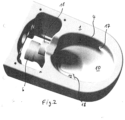
- the Figures 2 , 4-6 an inlet opening 17 for the flushing water, which is connected in a manner not recognizable to the flushing water connection piece 18.
- flushing water flows from this inlet opening 17 into the WC bowl 2 with an approximately tangential (in perspective from above) and otherwise approximately horizontal main flow direction.
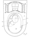
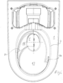
- the flushing water obviously hits the largest area of the first flow path 10 ( Figure 5 ), which in this sense connects to the inlet opening 17.
- a part of the first flow path 10 also exists, somewhat counterclockwise, next to the inlet opening 17 (in projection from above), and is therefore not immediately affected by the incoming flushing water.
- This area begins, strictly speaking, at the rear, where the first flow path disappears according to the figures, i.e. approximately at the intersection point of the vertical part of the axis cross, which in Figure 4 and 5 is drawn into the water level 8 to define its center.
- the first flow path 10 descends continuously and strictly monotonically, particularly with its center line 16, and thereby circulates (again with the center line 16 as a reference) the water level 8. Due to the quasi-asymptotic narrowing of the first flow path 10 at its beginning in the aforementioned rear region, one could, in a mathematical sense, actually use the rearmost point of the bowl's inner shape as the starting point, resulting in an angle of this circling around the water level 8 (relative to the marked center point therein and defined from the center line 16) of a good 230°.
- the outer concave edge runs during the described circulation of the first flow path 10 approximately at the lower Edge of the already mentioned steep wall area 3 of the bowl's inner shape, compare e.g. the X-mark on the left in Figure 3 and of course Figure 4 This applies from the "back” in a clockwise direction to the "bottom” and a little further. Then it runs continuously, curved and concave further inwards, with a gap between it and the steep wall area 3 according to Figure 5 additional structures are created. This concerns the already mentioned second convex edge 13 and the second concave edge 15 and a second flow path 14 defined between them.
- the second convex edge 13 and the second concave edge 15 define a second flow path 14 between them, wherein Figure 4
- the second convex edge 13 bends just before the edge of the outlet opening, because this is where the strongest convex curvatures occur.
- the second concave edge 15 forms, in a certain sense, apart from the inflow step 18 conditional height offset, a continuation of the first concave edge 11, compare the Figures 1 and 4-6 .
- the second flow path 14 thus has a pointed end at the front and rear, as seen from above, and another corner approximately in the middle inside.
- the second flow path 14 is considerably wider than the third flow path 19, namely approximately 45 mm. This refers to the transverse direction according to the Figures 4-6 , i.e. to the widest point at the inner corner of the second flow path 14.
- the flushing water flowing out of the inlet opening 17 initially flows clockwise, mostly along the first flow path 10 and, due to centrifugal force, also somewhat outside of it.
- the flushing water flow then enters the area of the inflow stage 18, a portion of it is directed inwards through the inflow stage 18 approximately into the middle of the water level 8, and another portion continues beyond the inflow stage 18 via the second flow path 14, at least approximately following the original rotating flow.
- the latter portion drops in height via the second flow path 14. In this respect, it ensures a vigorous rotating flushing water flow in the outlet opening as well, as already described in the cited prior art, with the inflow stage 18 additionally directing a portion of the flow approximately into the eye of the rotating flow in the outlet opening.
- Figure 8 shows the just described water flow with a photo of a real example analogous to the other figures.
- the perspective corresponds to the top view of the Figures 4-6
- the water is colored, which explains the dark hue, especially in the lower part.
- the embodiment also shows a third flow path 19, already mentioned abstractly above, clearly above and in the perspective from above slightly offset clockwise relative to the leading edge 18.
- this third flow path 19 holds a portion of the rotating flushing water flow, which initially runs outside the first flow path 10 and, due to centrifugal force, along the steep wall area 3, at a certain height. This portion is somewhat prevented from sinking too far downwards, especially after it has reached the Figure 4 lower area of the bowl's inner shape and the radii of curvature relevant for the centrifugal force increase.
- Line 20 is a tangential line to the outer edge of the water level 8
- line 21 is an extension of the proximal end of the inflow stage 18 to this edge. Both lines 20 and 21 meet at an angle of just under 90°, with line 21 pointing approximately towards the center of the water level 8.
- the intersection point of line 21 with the edge of the water level 8 lies, in the longitudinal direction from front to back, according to Figure 6 clearly within the foremost third of the central longitudinal axis of the water level 8, namely approximately three-quarters (thus dividing this central longitudinal axis in a ratio of 3:1).
- Figure 5 and 6 also show that the direction of line 21, i.e. the local direction of the inflow step 18 at its inner end, is rotated by almost 90° compared to the local direction of the inflow step 18 at its outer end, i.e. compared to the part of the inflow step 18 where it disappears outside or merges into the steep wall area 3 (in the Figures 4 and 5 where edges 13 and 15 meet).
- the inflow stage 18, with its curved shape, thus spans a substantial angular range, which is very streamlined due to its concave, rounded shape.
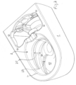
- the height 22 is the vertical offset between the first concave edge 11 and the second convex edge 13 and thus, in a sense, the height of the inflow step 18, while the height 23 is the vertical offset between the second concave edge 15 and the inner convex edge of the third flow path 19, i.e. the height of the third flow path 19 above the second flow path 14.
- the latter is significantly larger and is approximately 60 mm compared to approximately 20 mm for the former.
- Figure 7 These heights are without the Figures 4-6 drawn (dash-dotted) edges; however, they refer to these, in particular with the numerical values just given.
- the inflow step reaches a steepness of approximately 90° relative to the horizontal between the two edges 11 and 13.
- the entire toilet body 1 is a one-piece ceramic part in the form shown, which applies in particular to the complete inner shape of the bowl.
Landscapes
- Health & Medical Sciences (AREA)
- Life Sciences & Earth Sciences (AREA)
- Engineering & Computer Science (AREA)
- Hydrology & Water Resources (AREA)
- Public Health (AREA)
- Water Supply & Treatment (AREA)
- Sanitary Device For Flush Toilet (AREA)
Priority Applications (10)
| Application Number | Priority Date | Filing Date | Title |
|---|---|---|---|
| ES21189636T ES3033960T3 (en) | 2021-08-04 | 2021-08-04 | Wc with a specific shape of inner bowl |
| EP25167968.4A EP4592462A3 (de) | 2021-08-04 | 2021-08-04 | Wc mit spezifischer schlüsselinnenform |
| DK21189636.0T DK4130407T3 (da) | 2021-08-04 | 2021-08-04 | Toilet med specifik indvendig kummeform |
| EP21189636.0A EP4130407B1 (de) | 2021-08-04 | 2021-08-04 | Wc mit spezifischer schüsselinnenform |
| FIEP21189636.0T FI4130407T3 (fi) | 2021-08-04 | 2021-08-04 | WC erityisellä kulhon sisämuodolla |
| PCT/EP2022/069900 WO2023011889A1 (de) | 2021-08-04 | 2022-07-15 | Wc mit einer spezifischen schüsselinnenform |
| JP2024506137A JP2024527126A (ja) | 2021-08-04 | 2022-07-15 | 特種な内側形状のボウルを有する水洗便器 |
| AU2022321657A AU2022321657B2 (en) | 2021-08-04 | 2022-07-15 | Toilet having a specific inner bowl shape |
| CN202280054563.1A CN117813437A (zh) | 2021-08-04 | 2022-07-15 | 具有特殊便盆内部形状的抽水马桶 |
| ZA2023/10524A ZA202310524B (en) | 2021-08-04 | 2023-11-13 | Toilet having a specific inner bowl shape |
Applications Claiming Priority (1)
| Application Number | Priority Date | Filing Date | Title |
|---|---|---|---|
| EP21189636.0A EP4130407B1 (de) | 2021-08-04 | 2021-08-04 | Wc mit spezifischer schüsselinnenform |
Related Child Applications (3)
| Application Number | Title | Priority Date | Filing Date |
|---|---|---|---|
| EP25167968.4A Division EP4592462A3 (de) | 2021-08-04 | 2021-08-04 | Wc mit spezifischer schlüsselinnenform |
| EP25167968.4A Previously-Filed-Application EP4592462A3 (de) | 2021-08-04 | 2021-08-04 | Wc mit spezifischer schlüsselinnenform |
| EP25167968.4A Division-Into EP4592462A3 (de) | 2021-08-04 | 2021-08-04 | Wc mit spezifischer schlüsselinnenform |
Publications (2)
| Publication Number | Publication Date |
|---|---|
| EP4130407A1 EP4130407A1 (de) | 2023-02-08 |
| EP4130407B1 true EP4130407B1 (de) | 2025-05-14 |
Family
ID=77207114
Family Applications (2)
| Application Number | Title | Priority Date | Filing Date |
|---|---|---|---|
| EP21189636.0A Active EP4130407B1 (de) | 2021-08-04 | 2021-08-04 | Wc mit spezifischer schüsselinnenform |
| EP25167968.4A Pending EP4592462A3 (de) | 2021-08-04 | 2021-08-04 | Wc mit spezifischer schlüsselinnenform |
Family Applications After (1)
| Application Number | Title | Priority Date | Filing Date |
|---|---|---|---|
| EP25167968.4A Pending EP4592462A3 (de) | 2021-08-04 | 2021-08-04 | Wc mit spezifischer schlüsselinnenform |
Country Status (9)
| Country | Link |
|---|---|
| EP (2) | EP4130407B1 (da) |
| JP (1) | JP2024527126A (da) |
| CN (1) | CN117813437A (da) |
| AU (1) | AU2022321657B2 (da) |
| DK (1) | DK4130407T3 (da) |
| ES (1) | ES3033960T3 (da) |
| FI (1) | FI4130407T3 (da) |
| WO (1) | WO2023011889A1 (da) |
| ZA (1) | ZA202310524B (da) |
Family Cites Families (16)
| Publication number | Priority date | Publication date | Assignee | Title |
|---|---|---|---|---|
| US3723998A (en) * | 1972-04-05 | 1973-04-03 | R Wehr | Toilet bowl attachment |
| US4050101A (en) * | 1975-05-21 | 1977-09-27 | Clyde Sherman Logue | Baffle for toilet bowl |
| JPH1161950A (ja) * | 1997-08-08 | 1999-03-05 | Inax Corp | 洗落し洋風便器 |
| JP4721026B2 (ja) * | 2001-03-28 | 2011-07-13 | Toto株式会社 | 大便器装置 |
| PT2604761E (pt) | 2011-12-14 | 2015-05-13 | Geberit Int Ag | Vaso sanitário |
| US9359753B2 (en) | 2013-03-29 | 2016-06-07 | Toto Ltd. | Flush toilet |
| JP6242140B2 (ja) * | 2013-10-04 | 2017-12-06 | 株式会社Lixil | 汚物排出装置 |
| JP6331008B2 (ja) * | 2014-03-31 | 2018-05-30 | Toto株式会社 | 水洗大便器 |
| AU2015281776B2 (en) * | 2014-06-26 | 2019-12-19 | Caroma Industries Limited | A rimless toilet pan and a method of flushing same |
| JP2016148218A (ja) * | 2015-02-13 | 2016-08-18 | パナソニックIpマネジメント株式会社 | 水洗便器 |
| JP6495146B2 (ja) * | 2015-09-11 | 2019-04-03 | 株式会社Lixil | 水洗大便器 |
| EP3321438B1 (en) * | 2015-07-08 | 2020-11-11 | LIXIL Corporation | Flush toilet device |
| JP6796800B2 (ja) * | 2017-01-31 | 2020-12-09 | パナソニックIpマネジメント株式会社 | 水洗便器 |
| SI3412840T1 (sl) | 2017-06-09 | 2021-01-29 | Geberit International Ag | Stranišče |
| DK3444408T3 (da) | 2017-08-18 | 2020-12-21 | Geberit Int Ag | Toilet med skyllevandsforbindelse |
| CN214574415U (zh) * | 2021-02-22 | 2021-11-02 | 潮州市佳用瓷业有限公司 | 一种带有单孔的旋冲地排虹吸式马桶 |
-
2021
- 2021-08-04 ES ES21189636T patent/ES3033960T3/es active Active
- 2021-08-04 DK DK21189636.0T patent/DK4130407T3/da active
- 2021-08-04 FI FIEP21189636.0T patent/FI4130407T3/fi active
- 2021-08-04 EP EP21189636.0A patent/EP4130407B1/de active Active
- 2021-08-04 EP EP25167968.4A patent/EP4592462A3/de active Pending
-
2022
- 2022-07-15 WO PCT/EP2022/069900 patent/WO2023011889A1/de not_active Ceased
- 2022-07-15 AU AU2022321657A patent/AU2022321657B2/en active Active
- 2022-07-15 CN CN202280054563.1A patent/CN117813437A/zh active Pending
- 2022-07-15 JP JP2024506137A patent/JP2024527126A/ja active Pending
-
2023
- 2023-11-13 ZA ZA2023/10524A patent/ZA202310524B/en unknown
Also Published As
| Publication number | Publication date |
|---|---|
| EP4592462A3 (de) | 2025-10-15 |
| EP4130407A1 (de) | 2023-02-08 |
| FI4130407T3 (fi) | 2025-08-11 |
| ES3033960T3 (en) | 2025-08-11 |
| DK4130407T3 (da) | 2025-08-18 |
| AU2022321657B2 (en) | 2025-07-31 |
| AU2022321657A1 (en) | 2023-12-07 |
| JP2024527126A (ja) | 2024-07-19 |
| CN117813437A (zh) | 2024-04-02 |
| EP4592462A2 (de) | 2025-07-30 |
| ZA202310524B (en) | 2024-11-27 |
| WO2023011889A1 (de) | 2023-02-09 |
Similar Documents
| Publication | Publication Date | Title |
|---|---|---|
| EP2604761B1 (de) | Wasserklosett | |
| EP3951110B1 (de) | Spültoilette | |
| EP1928609B1 (de) | Duschkopf | |
| EP3412840B1 (de) | Wasserklosett | |
| EP2886729A1 (de) | Toilettenschüssel und Toilette | |
| DE9100565U1 (de) | Mischwasserentlastungs- bzw. -behandlungsanlage | |
| DE2928132C2 (de) | Vorrichtung zum Abscheiden von Feststoffen aus einem Flüssigkeitsstrom | |
| DE202021106357U1 (de) | Toilette mit Wasserspülung | |
| EP4130407B1 (de) | Wc mit spezifischer schüsselinnenform | |
| DE4139572C2 (de) | Siebanordnung für kreisförmige Regenwasserentlastungsanlagen | |
| EP0670969A1 (de) | Vorrichtung zur abflussbegrenzung und gleichzeitigen zwischenspeicherung von abwasser sowie abscheidung | |
| DE69023285T2 (de) | Toilettenschüssel. | |
| EP3106574A1 (de) | Leitungszweigstück für fallleitungen | |
| DE202021104161U1 (de) | WC mit spezifischer Schüsselinnenform | |
| EP0185109B1 (de) | Geruchsverschluss | |
| AT398598B (de) | Spülkippe | |
| DE112017006579T5 (de) | Spültoilette | |
| DE10204683B4 (de) | Becken | |
| EP3708724B1 (de) | Sanitärer ablauf mit überlaufschutz | |
| DE102007056294B3 (de) | Tauchwandsystem zur Schwimmstoffrückhaltung in Überlaufsystemen | |
| DE102022114693A1 (de) | Toilette mit Wasserspülung | |
| AT391850B (de) | Spuelkippe zur reinigung von rundbecken | |
| DE2639962A1 (de) | Siphon fuer sanitaerobjekte | |
| EP3486385A1 (de) | Sanitäreinrichtung | |
| EP1039021A1 (de) | Verfahren zum Nasssieben von Faserstoffsuspensionen in Drucksortierern und Drucksortierersieb |
Legal Events
| Date | Code | Title | Description |
|---|---|---|---|
| PUAI | Public reference made under article 153(3) epc to a published international application that has entered the european phase |
Free format text: ORIGINAL CODE: 0009012 |
|
| STAA | Information on the status of an ep patent application or granted ep patent |
Free format text: STATUS: REQUEST FOR EXAMINATION WAS MADE |
|
| 17P | Request for examination filed |
Effective date: 20220401 |
|
| AK | Designated contracting states |
Kind code of ref document: A1 Designated state(s): AL AT BE BG CH CY CZ DE DK EE ES FI FR GB GR HR HU IE IS IT LI LT LU LV MC MK MT NL NO PL PT RO RS SE SI SK SM TR |
|
| RBV | Designated contracting states (corrected) |
Designated state(s): AL AT BE BG CH CY CZ DE DK EE ES FI FR GB GR HR HU IE IS IT LI LT LU LV MC MK MT NL NO PL PT RO RS SE SI SK SM TR |
|
| STAA | Information on the status of an ep patent application or granted ep patent |
Free format text: STATUS: EXAMINATION IS IN PROGRESS |
|
| 17Q | First examination report despatched |
Effective date: 20230331 |
|
| GRAP | Despatch of communication of intention to grant a patent |
Free format text: ORIGINAL CODE: EPIDOSNIGR1 |
|
| STAA | Information on the status of an ep patent application or granted ep patent |
Free format text: STATUS: GRANT OF PATENT IS INTENDED |
|
| GRAJ | Information related to disapproval of communication of intention to grant by the applicant or resumption of examination proceedings by the epo deleted |
Free format text: ORIGINAL CODE: EPIDOSDIGR1 |
|
| STAA | Information on the status of an ep patent application or granted ep patent |
Free format text: STATUS: EXAMINATION IS IN PROGRESS |
|
| GRAP | Despatch of communication of intention to grant a patent |
Free format text: ORIGINAL CODE: EPIDOSNIGR1 |
|
| STAA | Information on the status of an ep patent application or granted ep patent |
Free format text: STATUS: GRANT OF PATENT IS INTENDED |
|
| INTG | Intention to grant announced |
Effective date: 20250219 |
|
| GRAS | Grant fee paid |
Free format text: ORIGINAL CODE: EPIDOSNIGR3 |
|
| GRAA | (expected) grant |
Free format text: ORIGINAL CODE: 0009210 |
|
| STAA | Information on the status of an ep patent application or granted ep patent |
Free format text: STATUS: THE PATENT HAS BEEN GRANTED |
|
| INTC | Intention to grant announced (deleted) | ||
| INTG | Intention to grant announced |
Effective date: 20250320 |
|
| AK | Designated contracting states |
Kind code of ref document: B1 Designated state(s): AL AT BE BG CH CY CZ DE DK EE ES FI FR GB GR HR HU IE IS IT LI LT LU LV MC MK MT NL NO PL PT RO RS SE SI SK SM TR |
|
| REG | Reference to a national code |
Ref country code: GB Ref legal event code: FG4D Free format text: NOT ENGLISH |
|
| REG | Reference to a national code |
Ref country code: CH Ref legal event code: EP |
|
| REG | Reference to a national code |
Ref country code: DE Ref legal event code: R096 Ref document number: 502021007454 Country of ref document: DE |
|
| REG | Reference to a national code |
Ref country code: IE Ref legal event code: FG4D Free format text: LANGUAGE OF EP DOCUMENT: GERMAN |
|
| P01 | Opt-out of the competence of the unified patent court (upc) registered |
Free format text: CASE NUMBER: APP_22481/2025 Effective date: 20250513 |
|
| REG | Reference to a national code |
Ref country code: ES Ref legal event code: FG2A Ref document number: 3033960 Country of ref document: ES Kind code of ref document: T3 Effective date: 20250811 Ref country code: FI Ref legal event code: FGE |
|
| REG | Reference to a national code |
Ref country code: DK Ref legal event code: T3 Effective date: 20250808 |
|
| REG | Reference to a national code |
Ref country code: NL Ref legal event code: FP |
|
| REG | Reference to a national code |
Ref country code: SE Ref legal event code: TRGR |
|
| PGFP | Annual fee paid to national office [announced via postgrant information from national office to epo] |
Ref country code: NL Payment date: 20250821 Year of fee payment: 5 |
|
| PG25 | Lapsed in a contracting state [announced via postgrant information from national office to epo] |
Ref country code: PT Free format text: LAPSE BECAUSE OF FAILURE TO SUBMIT A TRANSLATION OF THE DESCRIPTION OR TO PAY THE FEE WITHIN THE PRESCRIBED TIME-LIMIT Effective date: 20250915 |
|
| PGFP | Annual fee paid to national office [announced via postgrant information from national office to epo] |
Ref country code: ES Payment date: 20250917 Year of fee payment: 5 Ref country code: FI Payment date: 20250820 Year of fee payment: 5 |
|
| PGFP | Annual fee paid to national office [announced via postgrant information from national office to epo] |
Ref country code: DK Payment date: 20250821 Year of fee payment: 5 Ref country code: DE Payment date: 20250819 Year of fee payment: 5 |
|
| REG | Reference to a national code |
Ref country code: LT Ref legal event code: MG9D |
|
| PG25 | Lapsed in a contracting state [announced via postgrant information from national office to epo] |
Ref country code: GR Free format text: LAPSE BECAUSE OF FAILURE TO SUBMIT A TRANSLATION OF THE DESCRIPTION OR TO PAY THE FEE WITHIN THE PRESCRIBED TIME-LIMIT Effective date: 20250815 |
|
| PGFP | Annual fee paid to national office [announced via postgrant information from national office to epo] |
Ref country code: NO Payment date: 20250820 Year of fee payment: 5 |
|
| PG25 | Lapsed in a contracting state [announced via postgrant information from national office to epo] |
Ref country code: PL Free format text: LAPSE BECAUSE OF FAILURE TO SUBMIT A TRANSLATION OF THE DESCRIPTION OR TO PAY THE FEE WITHIN THE PRESCRIBED TIME-LIMIT Effective date: 20250514 |
|
| PG25 | Lapsed in a contracting state [announced via postgrant information from national office to epo] |
Ref country code: BG Free format text: LAPSE BECAUSE OF FAILURE TO SUBMIT A TRANSLATION OF THE DESCRIPTION OR TO PAY THE FEE WITHIN THE PRESCRIBED TIME-LIMIT Effective date: 20250514 |
|
| PGFP | Annual fee paid to national office [announced via postgrant information from national office to epo] |
Ref country code: BE Payment date: 20250820 Year of fee payment: 5 |
|
| PG25 | Lapsed in a contracting state [announced via postgrant information from national office to epo] |
Ref country code: HR Free format text: LAPSE BECAUSE OF FAILURE TO SUBMIT A TRANSLATION OF THE DESCRIPTION OR TO PAY THE FEE WITHIN THE PRESCRIBED TIME-LIMIT Effective date: 20250514 |
|
| PGFP | Annual fee paid to national office [announced via postgrant information from national office to epo] |
Ref country code: AT Payment date: 20251020 Year of fee payment: 5 Ref country code: FR Payment date: 20250821 Year of fee payment: 5 |
|
| PGFP | Annual fee paid to national office [announced via postgrant information from national office to epo] |
Ref country code: SE Payment date: 20250821 Year of fee payment: 5 Ref country code: CH Payment date: 20250901 Year of fee payment: 5 |
|
| PG25 | Lapsed in a contracting state [announced via postgrant information from national office to epo] |
Ref country code: RS Free format text: LAPSE BECAUSE OF FAILURE TO SUBMIT A TRANSLATION OF THE DESCRIPTION OR TO PAY THE FEE WITHIN THE PRESCRIBED TIME-LIMIT Effective date: 20250814 |
|
| PG25 | Lapsed in a contracting state [announced via postgrant information from national office to epo] |
Ref country code: IS Free format text: LAPSE BECAUSE OF FAILURE TO SUBMIT A TRANSLATION OF THE DESCRIPTION OR TO PAY THE FEE WITHIN THE PRESCRIBED TIME-LIMIT Effective date: 20250914 |
|
| PG25 | Lapsed in a contracting state [announced via postgrant information from national office to epo] |
Ref country code: LV Free format text: LAPSE BECAUSE OF FAILURE TO SUBMIT A TRANSLATION OF THE DESCRIPTION OR TO PAY THE FEE WITHIN THE PRESCRIBED TIME-LIMIT Effective date: 20250514 |
|
| PG25 | Lapsed in a contracting state [announced via postgrant information from national office to epo] |
Ref country code: SM Free format text: LAPSE BECAUSE OF FAILURE TO SUBMIT A TRANSLATION OF THE DESCRIPTION OR TO PAY THE FEE WITHIN THE PRESCRIBED TIME-LIMIT Effective date: 20250514 |
|
| PGFP | Annual fee paid to national office [announced via postgrant information from national office to epo] |
Ref country code: IT Payment date: 20251031 Year of fee payment: 5 |
|
| PG25 | Lapsed in a contracting state [announced via postgrant information from national office to epo] |
Ref country code: CZ Free format text: LAPSE BECAUSE OF FAILURE TO SUBMIT A TRANSLATION OF THE DESCRIPTION OR TO PAY THE FEE WITHIN THE PRESCRIBED TIME-LIMIT Effective date: 20250514 |
|
| PG25 | Lapsed in a contracting state [announced via postgrant information from national office to epo] |
Ref country code: EE Free format text: LAPSE BECAUSE OF FAILURE TO SUBMIT A TRANSLATION OF THE DESCRIPTION OR TO PAY THE FEE WITHIN THE PRESCRIBED TIME-LIMIT Effective date: 20250514 |
|
| PG25 | Lapsed in a contracting state [announced via postgrant information from national office to epo] |
Ref country code: SK Free format text: LAPSE BECAUSE OF FAILURE TO SUBMIT A TRANSLATION OF THE DESCRIPTION OR TO PAY THE FEE WITHIN THE PRESCRIBED TIME-LIMIT Effective date: 20250514 |
|
| PG25 | Lapsed in a contracting state [announced via postgrant information from national office to epo] |
Ref country code: RO Free format text: LAPSE BECAUSE OF FAILURE TO SUBMIT A TRANSLATION OF THE DESCRIPTION OR TO PAY THE FEE WITHIN THE PRESCRIBED TIME-LIMIT Effective date: 20250514 |
|
| REG | Reference to a national code |
Ref country code: DE Ref legal event code: R097 Ref document number: 502021007454 Country of ref document: DE |
|
| PLBE | No opposition filed within time limit |
Free format text: ORIGINAL CODE: 0009261 |
|
| STAA | Information on the status of an ep patent application or granted ep patent |
Free format text: STATUS: NO OPPOSITION FILED WITHIN TIME LIMIT |
|
| REG | Reference to a national code |
Ref country code: CH Ref legal event code: L10 Free format text: ST27 STATUS EVENT CODE: U-0-0-L10-L00 (AS PROVIDED BY THE NATIONAL OFFICE) Effective date: 20260325 |
|
| PG25 | Lapsed in a contracting state [announced via postgrant information from national office to epo] |
Ref country code: MC Free format text: LAPSE BECAUSE OF FAILURE TO SUBMIT A TRANSLATION OF THE DESCRIPTION OR TO PAY THE FEE WITHIN THE PRESCRIBED TIME-LIMIT Effective date: 20250514 |
|
| PG25 | Lapsed in a contracting state [announced via postgrant information from national office to epo] |
Ref country code: LU Free format text: LAPSE BECAUSE OF NON-PAYMENT OF DUE FEES Effective date: 20250804 |
|
| 26N | No opposition filed |
Effective date: 20260217 |