EP4130425B1 - Procédés et appareil destinés à être utilisés dans la complétion de puits de pétrole et de gaz - Google Patents
Procédés et appareil destinés à être utilisés dans la complétion de puits de pétrole et de gaz Download PDFInfo
- Publication number
- EP4130425B1 EP4130425B1 EP22198301.8A EP22198301A EP4130425B1 EP 4130425 B1 EP4130425 B1 EP 4130425B1 EP 22198301 A EP22198301 A EP 22198301A EP 4130425 B1 EP4130425 B1 EP 4130425B1
- Authority
- EP
- European Patent Office
- Prior art keywords
- well
- tubing
- annular
- annular packer
- packer
- Prior art date
- Legal status (The legal status is an assumption and is not a legal conclusion. Google has not performed a legal analysis and makes no representation as to the accuracy of the status listed.)
- Active
Links
Images





Classifications
-
- E—FIXED CONSTRUCTIONS
- E21—EARTH OR ROCK DRILLING; MINING
- E21B—EARTH OR ROCK DRILLING; OBTAINING OIL, GAS, WATER, SOLUBLE OR MELTABLE MATERIALS OR A SLURRY OF MINERALS FROM WELLS
- E21B33/00—Sealing or packing boreholes or wells
- E21B33/10—Sealing or packing boreholes or wells in the borehole
- E21B33/12—Packers; Plugs
- E21B33/122—Multiple string packers
-
- E—FIXED CONSTRUCTIONS
- E21—EARTH OR ROCK DRILLING; MINING
- E21B—EARTH OR ROCK DRILLING; OBTAINING OIL, GAS, WATER, SOLUBLE OR MELTABLE MATERIALS OR A SLURRY OF MINERALS FROM WELLS
- E21B33/00—Sealing or packing boreholes or wells
- E21B33/10—Sealing or packing boreholes or wells in the borehole
- E21B33/12—Packers; Plugs
- E21B33/1208—Packers; Plugs characterised by the construction of the sealing or packing means
- E21B33/1212—Packers; Plugs characterised by the construction of the sealing or packing means including a metal-to-metal seal element
-
- E—FIXED CONSTRUCTIONS
- E21—EARTH OR ROCK DRILLING; MINING
- E21B—EARTH OR ROCK DRILLING; OBTAINING OIL, GAS, WATER, SOLUBLE OR MELTABLE MATERIALS OR A SLURRY OF MINERALS FROM WELLS
- E21B17/00—Drilling rods or pipes; Flexible drill strings; Kellies; Drill collars; Sucker rods; Cables; Casings; Tubings
- E21B17/02—Couplings; joints
- E21B17/04—Couplings; joints between rod or the like and bit or between rod and rod or the like
- E21B17/042—Threaded
-
- E—FIXED CONSTRUCTIONS
- E21—EARTH OR ROCK DRILLING; MINING
- E21B—EARTH OR ROCK DRILLING; OBTAINING OIL, GAS, WATER, SOLUBLE OR MELTABLE MATERIALS OR A SLURRY OF MINERALS FROM WELLS
- E21B19/00—Handling rods, casings, tubes or the like outside the borehole, e.g. in the derrick; Apparatus for feeding the rods or cables
-
- E—FIXED CONSTRUCTIONS
- E21—EARTH OR ROCK DRILLING; MINING
- E21B—EARTH OR ROCK DRILLING; OBTAINING OIL, GAS, WATER, SOLUBLE OR MELTABLE MATERIALS OR A SLURRY OF MINERALS FROM WELLS
- E21B23/00—Apparatus for displacing, setting, locking, releasing or removing tools, packers or the like in boreholes or wells
- E21B23/06—Apparatus for displacing, setting, locking, releasing or removing tools, packers or the like in boreholes or wells for setting packers
-
- E—FIXED CONSTRUCTIONS
- E21—EARTH OR ROCK DRILLING; MINING
- E21B—EARTH OR ROCK DRILLING; OBTAINING OIL, GAS, WATER, SOLUBLE OR MELTABLE MATERIALS OR A SLURRY OF MINERALS FROM WELLS
- E21B29/00—Cutting or destroying pipes, packers, plugs or wire lines, located in boreholes or wells, e.g. cutting of damaged pipes, of windows; Deforming of pipes in boreholes or wells; Reconditioning of well casings while in the ground
- E21B29/10—Reconditioning of well casings, e.g. straightening
-
- E—FIXED CONSTRUCTIONS
- E21—EARTH OR ROCK DRILLING; MINING
- E21B—EARTH OR ROCK DRILLING; OBTAINING OIL, GAS, WATER, SOLUBLE OR MELTABLE MATERIALS OR A SLURRY OF MINERALS FROM WELLS
- E21B31/00—Fishing for or freeing objects in boreholes or wells
- E21B31/007—Fishing for or freeing objects in boreholes or wells fishing tools with means for attaching comprising fusing or sticking
-
- E—FIXED CONSTRUCTIONS
- E21—EARTH OR ROCK DRILLING; MINING
- E21B—EARTH OR ROCK DRILLING; OBTAINING OIL, GAS, WATER, SOLUBLE OR MELTABLE MATERIALS OR A SLURRY OF MINERALS FROM WELLS
- E21B33/00—Sealing or packing boreholes or wells
- E21B33/02—Surface sealing or packing
- E21B33/03—Well heads; Setting-up thereof
- E21B33/04—Casing heads; Suspending casings or tubings in well heads
-
- E—FIXED CONSTRUCTIONS
- E21—EARTH OR ROCK DRILLING; MINING
- E21B—EARTH OR ROCK DRILLING; OBTAINING OIL, GAS, WATER, SOLUBLE OR MELTABLE MATERIALS OR A SLURRY OF MINERALS FROM WELLS
- E21B33/00—Sealing or packing boreholes or wells
- E21B33/10—Sealing or packing boreholes or wells in the borehole
- E21B33/12—Packers; Plugs
- E21B33/1208—Packers; Plugs characterised by the construction of the sealing or packing means
-
- E—FIXED CONSTRUCTIONS
- E21—EARTH OR ROCK DRILLING; MINING
- E21B—EARTH OR ROCK DRILLING; OBTAINING OIL, GAS, WATER, SOLUBLE OR MELTABLE MATERIALS OR A SLURRY OF MINERALS FROM WELLS
- E21B33/00—Sealing or packing boreholes or wells
- E21B33/10—Sealing or packing boreholes or wells in the borehole
- E21B33/12—Packers; Plugs
- E21B33/124—Units with longitudinally-spaced plugs for isolating the intermediate space
-
- E—FIXED CONSTRUCTIONS
- E21—EARTH OR ROCK DRILLING; MINING
- E21B—EARTH OR ROCK DRILLING; OBTAINING OIL, GAS, WATER, SOLUBLE OR MELTABLE MATERIALS OR A SLURRY OF MINERALS FROM WELLS
- E21B33/00—Sealing or packing boreholes or wells
- E21B33/10—Sealing or packing boreholes or wells in the borehole
- E21B33/13—Methods or devices for cementing, for plugging holes, crevices or the like
-
- E—FIXED CONSTRUCTIONS
- E21—EARTH OR ROCK DRILLING; MINING
- E21B—EARTH OR ROCK DRILLING; OBTAINING OIL, GAS, WATER, SOLUBLE OR MELTABLE MATERIALS OR A SLURRY OF MINERALS FROM WELLS
- E21B33/00—Sealing or packing boreholes or wells
- E21B33/10—Sealing or packing boreholes or wells in the borehole
- E21B33/13—Methods or devices for cementing, for plugging holes, crevices or the like
- E21B33/14—Methods or devices for cementing, for plugging holes, crevices or the like for cementing casings into boreholes
-
- E—FIXED CONSTRUCTIONS
- E21—EARTH OR ROCK DRILLING; MINING
- E21B—EARTH OR ROCK DRILLING; OBTAINING OIL, GAS, WATER, SOLUBLE OR MELTABLE MATERIALS OR A SLURRY OF MINERALS FROM WELLS
- E21B36/00—Heating, cooling or insulating arrangements for boreholes or wells, e.g. for use in permafrost zones
- E21B36/008—Heating, cooling or insulating arrangements for boreholes or wells, e.g. for use in permafrost zones using chemical heat generating means
-
- E—FIXED CONSTRUCTIONS
- E21—EARTH OR ROCK DRILLING; MINING
- E21B—EARTH OR ROCK DRILLING; OBTAINING OIL, GAS, WATER, SOLUBLE OR MELTABLE MATERIALS OR A SLURRY OF MINERALS FROM WELLS
- E21B43/00—Methods or apparatus for obtaining oil, gas, water, soluble or meltable materials or a slurry of minerals from wells
- E21B43/02—Subsoil filtering
- E21B43/10—Setting of casings, screens, liners or the like in wells
Definitions
- eutectic alloy such as bismuth alloy
- the first aspect provides a gas or oil well tubing having an annular packer mounted thereon, wherein the annular packer is formed from a eutectic alloy or any other bismuth alloy.
- tubing of the first aspect may refer to a section of well lining, a section of well casing or a section of production tubing.
- Mounting the eutectic annular packer on the tubing that is then deployed in the formation of an oil/gas well means that the alloy is already in situ within the well. In this way, when a leak is detected it can be remedied by simply heating the region of the tubing where the annular packer is mounted.
- tubing of the first aspect could be effectively deployed just above the cement seal so that when melted the alloy of the annular packer can quickly and easily flow into any cracks/gaps formed in the cement.
- tubing could be completely surrounded by and embedded within the cement.
- the conduits may be provided as channels in the inner and/or outer circumferential surface of the annular packer. Alternatively the conduits may be provided as through holes in the main body of the annular packer.
- the annular packer may be mounted on the inner surface of the tubing. It is envisioned that this arrangement is particularly suitable when the tubing is a well casing or well lining.
- the annular packer may comprise multiple component parts which are combinable to form the complete annulus when mounted on the tubing. In this way the production step of mounting the annular packer on the tubing is made quicker and easier.
- the annular packer may consist of two of more sections that can be located on the tubing in a stacked arrangement (that is, one on top of another along a length of the tubing). In this way various lengths of annular packer can be achieved by stacking varying numbers of packer sections on the tubing.
- stackable packer sections may be provided with alignment means that ensure that the sections stack correctly. This is particularly important so that the conduits of the complete annular packer locate in alignment with one another and in doing ensure that there is a flow path running through the complete annular packer for the cement to pass through.
- conduit clearance means are held in a 'stretched' state by the annular packer until the alloy of the packer is melted, at which time the conduit clearance means can return to their preferred (i.e. non-stretched) state. In this way the conduit clearance means 'spring back' and apply a breaking force to any cement that may have set within the conduit(s).
- the resiliently biased conduit clearance means may be provided with a leading edge that is configured to enhance the breaking capability of the conduit clearance means when it is sprung against the cement in the conduit.
- the annular packer may be provided with one or more rubber seals that are configured to form cement-tight seals between the annular packer and an adjacent well casing or tubing.
- the rubber seals may be located on the inner surface, the outer surface or on both the inner and outer surfaces of the annular packer so as to facilitate the formation of seals with well casings and tubing that are located either on the outside of the packer or the inside of the packer.
- each section may be provided with one or more rubber seals on the surfaces thereof that make contact with another packer section.
- seals around any conduits provided in the packer section so as to provide a cement-tight seal. This is particularly desirable when the conduits are formed through the middle (i.e. main body) of the packer section.
- Preferably multiple rubber seals are provided on the leading and trailing sections of a stackable annular packer. This allows for some rubber seals to fail during the deployment of the annular packer and yet still maintain the required seal between adjacent tubing.
- annular seal may also serve to secure the well liner in place relative to the surrounding surface. That is to say the bond formed by the annular packer is strong enough to provide a weight bearing function.
- additional securing means such as hydraulically operated 'dogs' or 'slips', may also be provided to help securely retain the liner hanger in an operating position.
- a third aspect relates to the use of the tubing of the first aspect of the present invention in casing drilling.
- Such cavities/fissures can provide routes of egress for the drilling fluids flow away, thereby negatively affecting the drilling fluid levels and requiring drilling operations to be stopped until the cavity/fissure can be plugged to prevent the drilling fluid being lost.
- the process of plugging the cavity/fissure requires the complete removal of the drilling tool so that suitable plugging material (such as cement) can be delivered down the well bore to close off the cavity/fissure.
- the alloy suitable for sealing of cavities/fissures that may present during the drilling process can be quickly deployed without the need to remove the drilling tool by simply heating the annular packer and allowing the alloy to flow in to the cavities/fissures, where the alloy can cool and form plugs.
- the present disclosure also provides a method of manufacturing the tubing of the first aspect of the present invention, which in turn can be further adapted for use in the second and third aspects of the present invention.
- oil/gas well tubing of the present invention will be prefabricated in a factory, or possibly on site, before the tubing is deployed down a well bore. This is in clear contrast to the existing approach of deploying eutectic or other bismuth based alloys into the annular space located between existing well tubing and an underground formation (or indeed between adjacent well tubing) and then melting it.
- the annular packer is provided in the form of multiple component parts and the step of mounting the annular packer to the tubing involves securing the component parts together around the circumference of the tubing to complete the annulus.
- This approach is considered most appropriate for producing the variants of the tubing according to the present invention that has the annular packer mounted on the outer surface thereof.
- the present disclosure also provides a method of sealing a leak in a completed oil/gas well using the tubing of the present invention by heating the annular packer in situ to melt the alloy and seal the leak.
- a heating tool such as a chemical heater
- the tubing may further comprise heating means that can be activated remotely to melt the alloy.
- the heating means are preferably in the form of a chemical heat source.
- the externally mounted annular packer might preferably be formed from multiple component parts that combine to surround the length of production pipe 2 so that the process of mounting (and possibly remounting) the annular packer is made easier.
- the diameter of the annular packer 3 is sufficient to provide a close fit with the outer wall of the well 5, which may be provided by a rock formation 4 or as appropriate a well casing or lining.
- tubing 1 and 6 are typically connected together above ground and then deployed down the well. However in order to clearly illustrate that tubing 1 and 6 are initially distinct they are initially shown in figure 1 as being separate.
- tubing 1 is attached to the top of the tubing 6. It is envisioned that advantageously the tubing 1 of the present invention may be connected to existing production tubing 6 using the collar joint of the present invention shown in figures 16 and 17 , although this is not considered essential. It is appreciated that alternative approaches to deploying a series of sections of well tubing can be employed in concert with the present invention.
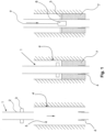
- cement 7 can be poured or pumped into the annular space between the formation 4 and the pipework (or, if appropriate, between a well casing/lining and the pipework). Once set the cement 7 will seal the well 5 so that the only access to the oil/gas deposit is via the production tubing 1,6.
- the alloy 3 of the annular packer which may be a eutectic alloy or other forms of bismuth alloy, cools it expands and plugs the cracks/gaps and reseals the cement plug 7 and stops the leak.
- the cement is poured (or pumped) into the annular space after the tubing 1, with its annular packer 3, has been deployed within the well.
- annular packer 3 In arrangements where the diameter of the annular packer 3 is close to the internal diameter of the rock formation 4 (or well casing/lining -not shown) it is considered advantageous to provide the annular packer 3 with conduits to facilitate the passage of cement through and around the annular packer 3 so that it can reach the lower regions of the well 5.
- tubing 1 may also be completely surrounded by and embedded within the cement 7.
- Figures 1a and 1b show such arrangements.
- the embodiment of the tubing shown in Figure 1a has an annular packer 3 of a reduced diameter that does not extend all the way to the outer formation (or casing). In is envisioned that such embodiment is suitable for sealing micro annuli leaks; such as those formed by constant expansion and contraction of the production tubing (see above).
- FIG. 1b has an annular packer 3 with a diameter that extends to the surrounding formation (or casing). It is envisioned that this embodiment is more suitable for repairing cracks that extend across the entire cement seal.
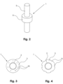
- Figure 4 shows a second variant of the annular packer 3, which is provided with a plurality of channels 11 in the outer surface of the annular packer 3.
- the well casing 12 is deployed within a well hole.
- the well casing 12 is secured in place within the well hole using standard means, although it is envisaged that alloy annular packer might also be used for this purpose.
- the well casing (or well liner) may be provided with a skirt or 'cool area' to slow the flow of the melted alloy so that it is not lost down the well but instead cools in the target region. Further details of suitable skirting can be found in International PCT Application No. WO2011/151271 . It is appreciated that the well fluids will act to quickly cool the heated alloy ensuring that it is not is a flowing state for very long.
- the skirt may further comprise a swellable or intumescent material that is caused to expand when exposed to heat. This further enhances the ability of the skirt to check the flow of the molten alloy so that it can cool in the target region.
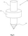
- Figure 6 shows an embodiment according to the third aspect.
- the drilling casing 20 comprises a section of tubing in the form of a well casing 21.
- An annular packer 22 is mounted in the outer surface of the casing 21.
- a drill head 23 On the leading end of the casing is provided a drill head 23. In use the entire drilling casing 20 is rotated to effect a drilling action on a formation that is comprised of loose material.
- the diameter of the drilling head 23 would in practise be closer to that of the annular packer so that the well bore being formed can accommodate the passage of the annular packer 22 as the drilling casing 20 carries out the drilling operation.
- the operation of the drilling casing 20 will be better appreciated upon consideration of Figure 7 , which show the key stages of a drilling action.
- the first stage shown in Figure 7 represents the standard drilling operation wherein the drilling casing 20 is rotated about its central axis so as to create a well bore 25 in the formation 24.
- Drilling fluid 26 is provided within the well bore 25 (possibly via the casing 20) to assist the drilling process (i.e. cool the drilling tool and facilitate removal of swarf/drilling waste from the drill face).
- the heating means is shown as a separate heating tool that is deployed down the well, via the inside of the casing 21, until it reaches the target region adjacent the annular packer 22.
- an alternative heat source preferably in the form of a chemical heat source, might be provided on the drilling casing 20 before it is deployed. This could be activated from the surface or remotely (e.g. using a pressure pulse, radio wave, etc).
- annular packer might also be mounted on the inner surface of suitable tubing without departing from the scope of the present invention.
- suitable tubing may include sections of well casing and well lining.
- Figure 8 shows an embodiment of the tubing 30 of first aspect wherein the annular packer 32 is mounted within the section of well casing 31 on an inner surface thereof.
- Figure 9 shows the variant of the annular packer 32 with cement by-pass conduits in the form of through holes 33
- Figure 10 shows a variant of the annular packer 32 is provided with channels 34 in the inner circumferential surface.
- Figure 11 show three views (a combined, an exploded, and a cross-sectional) of a preferred stackable arrangement of the annular packer 80.
- the annular packer is shown without a well casing/tubing as such is not essential to the provision of an operational annular packer.
- each section On the outside of each section is provided at least one conduit clearance means 85, which essentially comprise a metal spring ring that has been stretched fit around the annular packer 80.
- Each spring ring is retained within a recess 91 (see Figure 12 ).
- the spring ring may preferably be made from steel as this is a relatively cheap material. However, in cases where higher temperature tolerances are required it is envisioned that alternative metals and alloys may be employed to form the spring ring.
- the seals 86 which are only provided on the end sections 81, are similar in nature to the externally mounted seals 84.
- the inner conduit clearance means 87 are once again provided by spring rings. However in contrast to the outer means 85 the inner spring rings are squeezed into the inner space of the annular packer.
- the alloy 88 is cast with one or more recesses 91, 92 on its inner and outer surface to receive the above described conduit clearance means 85, 87.
- the section of eutectic alloy annular packer is also provided with a void 90 into which tubing may be received.
- the conduit 89 is defined by the eutectic alloy 88. However once cement has been allowed to flow through the conduit 89, as when cement is being pumped down hole past the annular packer via one or more conduits 89, some cement can remain in the conduit and set there.
- the end section 81 is provided with a pair of seals 84 on the outer surface of the end section and on the inner surface of the end section.
- the seals are provided within recesses located towards the leading edge of the end section 81to isolate the main body of the eutectic alloy 88 from any cement that is pumped into the well hole.
- the pairs of seals are provided on both the inner surface and the outer surface so as to allow for potential failure of one of the seals during the deployment of the annular packer 80. It is envisaged that more or less seals might be employed as required.
- Figure 14 is provided to show a further enlarged cross-sectional view of a seal when the packer is inserted within a tubing 93.
- the seal 84 makes contact with the tubing 93 and in doing so forms a seal.
- One or more centralisers 96 are provided at the ends of the annular packer 80 to ensure it remains centralised as it is deployed down the well casing/tubing 110. This is desirable as it ensures that the distance between the inner tube (upon which the annular packer is mounted) 97 and the outer well casing/tubing 110 is substantially the same all around the circumference. This in turn aids the formation of a reliable eutectic plug.
- the cement is then allowed to set and form the cement plug between the inner 97 and outer 110 tubes.
- the annular space above the annular packer may or may not be filled with cement 120 depending on the operational requirements of the well.
- conduits 89 are filled with cement 120.
- the presence of solid cement path within the body of the alloy is undesirable because such might provide a potential leakage point within any alloy plug formed.
- cement paths formed within the conduits are broken up. This function is carried out by the conduit clearance means 85, 87.
- conduit clearance means 85, 87 once the alloy 88 of the packer 80 has begun to melt the spring rings are no longer held in position and can spring back towards the conduits. This action imparts a breaking force on the cement rods and smashes them in to smaller non-continuous pieces.
- annular packer between producing zones in open hole gravel pack (OHGP).
- OHGP open hole gravel pack
- Figures 16 and 17 provide cross-sectional views of an embodiment of a collar joint 40 according to a fourth aspect.
- a leak heater 49 is deployed via the tubing 45 to a point that is adjacent the collar joint 40 via a standard delivery means 50 (e.g. wire line). Once in place the heater 49 can be operated to heat the alloy rings, which can then flow under gravity into the screw threaded joint located below the respective recesses 47, 48. The alloy is then allowed to cool and expand within screw threaded region to enhance the seal formed.
- a standard delivery means 50 e.g. wire line
- alloy rings are intended for use only when a leak develops at a joint it is also envisaged that the alloy may be deployed even when there is not leak with the sole purpose of providing an enhanced seal at a joint section.
Landscapes
- Engineering & Computer Science (AREA)
- Life Sciences & Earth Sciences (AREA)
- Geology (AREA)
- Mining & Mineral Resources (AREA)
- Environmental & Geological Engineering (AREA)
- Fluid Mechanics (AREA)
- Physics & Mathematics (AREA)
- General Life Sciences & Earth Sciences (AREA)
- Geochemistry & Mineralogy (AREA)
- Mechanical Engineering (AREA)
- Marine Sciences & Fisheries (AREA)
- Earth Drilling (AREA)
- Pipe Accessories (AREA)
- Consolidation Of Soil By Introduction Of Solidifying Substances Into Soil (AREA)
- Auxiliary Devices For Machine Tools (AREA)
Claims (6)
- Procédé de déploiement d'un dispositif de suspension de chemisage dans un puits de gaz ou de pétrole pour fixer ou suspendre un chemisage de puits (13) à une paroi interne d'un tubage de puits (12) dudit puits de gaz ou de pétrole, ledit procédé consistant à :fournir un packer annulaire (14) dans un espace annulaire entre le chemisage de puits (13) et le tubage de puits (12) au niveau d'un emplacement adjacent à une section supérieure du chemisage de puits qui est la plus proche de la surface du sol (13), ledit packer annulaire (14) étant formé à partir d'un alliage eutectique ou d'un autre alliage à base de bismuth ;acheminer un dispositif de chauffage (15) dans le puits jusqu'à une région cible où le tubage de puits (12), le packer annulaire (14) et le chemisage de puits (13) sont alignés, puis activer le dispositif de chauffage (15) pour faire fondre l'alliage du packer annulaire (14) ;laisser l'alliage s'écouler dans l'espace annulaire entre le chemisage de puits (13) et le tubage de puits (12), puis se refroidir et se resolidifier afin qu'il forme un joint annulaire (14a) entre le tubage de puits (12) et le chemisage de puits (13) ; etle procédé étant caractérisé en ce que le joint annulaire (14a) est suffisamment résistant pour assurer une fonction porteuse de poids qui permet de suspendre le chemisage de puits (13) au tubage de puits (12).
- Procédé selon la revendication 1, dans lequel le packer annulaire (14) est situé sur la surface extérieure du chemisage du puits.
- Procédé selon la revendication 1, dans lequel le packer annulaire (14) est situé sur la surface intérieure du tubage de puits (12).
- Dispositif de suspension de chemisage destiné à être utilisé dans un puits de gaz ou de pétrole, comprenant un chemisage de puits (13) sur lequel est monté un packer annulaire (14), le packer annulaire étant formé à partir d'un alliage eutectique ou d'un autre alliage à base de bismuth qui, en fondant, s'écoule dans un espace annulaire entre le chemisage de puits (13) et un tubage de puits environnant (12), puis se refroidit pour sceller l'espace annulaire ;le packer annulaire (14) étant situé à l'extérieur du chemisage du puits (13) vers une section supérieure de celui-ci, ladite section supérieure étant la section du chemisage du puits qui est la plus proche de la surface du sol ; etle dispositif de suspension de chemisage étant caractérisé en ce que le packer annulaire (14) est configuré pour former dans l'espace annulaire un joint (14a) suffisamment résistant pour assurer une fonction porteuse de poids qui permet de suspendre le chemisage de puits au tubage de puits (12) environnant.
- Dispositif de suspension de chemisage selon la revendication 4, dans lequel le packer annulaire comprend de multiples segments d'anneau qui peuvent être combinés pour former le packer annulaire complet qui encercle le chemisage de puits.
- Dispositif de suspension de chemisage selon la revendication 4, dans lequel le packer annulaire consiste en deux sections ou plus qui sont situées dans un agencement empilé le long de la longueur du chemisage de puits.
Applications Claiming Priority (4)
| Application Number | Priority Date | Filing Date | Title |
|---|---|---|---|
| GBGB1414565.0A GB201414565D0 (en) | 2014-08-15 | 2014-08-15 | Methods and apparatus for use in oil and gas well completion |
| GB1505750.8A GB2529275B (en) | 2014-08-15 | 2015-04-02 | Methods and apparatus for use in oil and gas well completion |
| PCT/GB2015/052347 WO2016024122A2 (fr) | 2014-08-15 | 2015-08-14 | Procédés et appareil pour utilisation lors de la complétion de puits de pétrole et de gaz |
| EP15753148.4A EP3180491B1 (fr) | 2014-08-15 | 2015-08-14 | Procédés et appareil pour utilisation lors de la complétion de puits de pétrole et de gaz |
Related Parent Applications (2)
| Application Number | Title | Priority Date | Filing Date |
|---|---|---|---|
| EP15753148.4A Division EP3180491B1 (fr) | 2014-08-15 | 2015-08-14 | Procédés et appareil pour utilisation lors de la complétion de puits de pétrole et de gaz |
| EP15753148.4A Division-Into EP3180491B1 (fr) | 2014-08-15 | 2015-08-14 | Procédés et appareil pour utilisation lors de la complétion de puits de pétrole et de gaz |
Publications (2)
| Publication Number | Publication Date |
|---|---|
| EP4130425A1 EP4130425A1 (fr) | 2023-02-08 |
| EP4130425B1 true EP4130425B1 (fr) | 2025-04-16 |
Family
ID=51662526
Family Applications (5)
| Application Number | Title | Priority Date | Filing Date |
|---|---|---|---|
| EP19172004.4A Active EP3578749B1 (fr) | 2014-08-15 | 2015-08-14 | Outils de chevauchement de fond de trou |
| EP15753149.2A Active EP3180492B1 (fr) | 2014-08-15 | 2015-08-14 | Outils de fond de trou de puits et procédés d'utilisation associés |
| EP15753981.8A Active EP3126617B1 (fr) | 2014-08-15 | 2015-08-14 | Outil de repêchage de fond de puits |
| EP15753148.4A Active EP3180491B1 (fr) | 2014-08-15 | 2015-08-14 | Procédés et appareil pour utilisation lors de la complétion de puits de pétrole et de gaz |
| EP22198301.8A Active EP4130425B1 (fr) | 2014-08-15 | 2015-08-14 | Procédés et appareil destinés à être utilisés dans la complétion de puits de pétrole et de gaz |
Family Applications Before (4)
| Application Number | Title | Priority Date | Filing Date |
|---|---|---|---|
| EP19172004.4A Active EP3578749B1 (fr) | 2014-08-15 | 2015-08-14 | Outils de chevauchement de fond de trou |
| EP15753149.2A Active EP3180492B1 (fr) | 2014-08-15 | 2015-08-14 | Outils de fond de trou de puits et procédés d'utilisation associés |
| EP15753981.8A Active EP3126617B1 (fr) | 2014-08-15 | 2015-08-14 | Outil de repêchage de fond de puits |
| EP15753148.4A Active EP3180491B1 (fr) | 2014-08-15 | 2015-08-14 | Procédés et appareil pour utilisation lors de la complétion de puits de pétrole et de gaz |
Country Status (8)
| Country | Link |
|---|---|
| US (7) | US10370931B2 (fr) |
| EP (5) | EP3578749B1 (fr) |
| CA (3) | CA2987496C (fr) |
| DK (4) | DK3126617T3 (fr) |
| GB (2) | GB201414565D0 (fr) |
| NO (1) | NO3126617T3 (fr) |
| SA (2) | SA517380901B1 (fr) |
| WO (3) | WO2016024123A1 (fr) |
Families Citing this family (37)
| Publication number | Priority date | Publication date | Assignee | Title |
|---|---|---|---|---|
| GB2480869B (en) | 2010-06-04 | 2017-01-11 | Bisn Tec Ltd | Method and apparatus for use in well abandonment |
| GB201223055D0 (en) | 2012-12-20 | 2013-02-06 | Carragher Paul | Method and apparatus for use in well abandonment |
| GB201406071D0 (en) | 2014-04-04 | 2014-05-21 | Bisn Tec Ltd | Well Casing / Tubing Disposal |
| GB201414565D0 (en) * | 2014-08-15 | 2014-10-01 | Bisn Oil Tools Ltd | Methods and apparatus for use in oil and gas well completion |
| GB2549982B (en) | 2016-05-06 | 2019-10-30 | Bisn Tec Ltd | Heat sources and alloys for use in down-hole operations |
| GB2551693B (en) | 2016-05-24 | 2021-09-15 | Bisn Tec Ltd | Down-hole chemical heater and methods of operating such |
| MY203147A (en) * | 2016-08-19 | 2024-06-11 | Bisn Tec Ltd | Downhole operations relating to open hole gravel packs and tools for use therein |
| GB2562208B (en) * | 2017-04-04 | 2021-04-07 | Bisn Tec Ltd | Improvements relating to thermally deformable annular packers |
| WO2018204054A1 (fr) * | 2017-05-01 | 2018-11-08 | Conocophillips Company | Joint métallique pour forage à colonne perdue |
| CA3100822A1 (fr) * | 2017-05-24 | 2018-11-29 | Bisn Tec Ltd | Ensemble de deploiement d'outil de fond de trou a separation amelioree du dispositif de chauffage et procedes d'utilisation de celui-ci |
| WO2019006141A1 (fr) * | 2017-06-29 | 2019-01-03 | Conocophillips Company | Procédés, systèmes et dispositifs permettant de boucher des fuites d'outil étagé |
| GB2568519B (en) | 2017-11-17 | 2022-09-28 | Bisn Tec Ltd | An expandable eutectic alloy based downhole tool and methods of deploying such |
| US10844699B2 (en) * | 2018-05-29 | 2020-11-24 | Saudi Arabian Oil Company | By-pass system and method for inverted ESP completion |
| US11846418B2 (en) * | 2018-12-28 | 2023-12-19 | Robertson Intellectual Properties, LLC | Protective material for fuel system |
| GB2583372B (en) * | 2019-04-26 | 2022-03-02 | Isol8 Holdings Ltd | Downhole sealing methods and apparatus |
| US10975658B2 (en) | 2019-05-17 | 2021-04-13 | Baker Hughes Oilfield Operations Llc | Wellbore isolation barrier including negative thermal expansion material |
| NO20210121A1 (en) * | 2020-02-10 | 2021-08-11 | Wellbore Integrity Solutions Llc | Patch for joining downhole ends of pipes |
| DK4168645T3 (da) | 2020-06-22 | 2025-12-22 | Bisn Tec Ltd | Prop med kompositender og fremgangsmåde til formning og anvendelse |
| US11448034B2 (en) | 2020-07-13 | 2022-09-20 | Saudi Arabian Oil Company | Removable plugging method and apparatus |
| CA3189554A1 (fr) | 2020-07-15 | 2022-01-20 | Conocophillips Company | Systeme de reconnexion d'effondrement de puits |
| CN112096336A (zh) * | 2020-09-07 | 2020-12-18 | 深圳百途石油技术服务有限公司 | 一种气井环空带压的治理方法及其装置 |
| GB202111796D0 (en) | 2021-08-17 | 2021-09-29 | Bisn Tec Ltd | A downhole external catch tool and methods of using such |
| GB2612622A (en) | 2021-11-05 | 2023-05-10 | Bisn Tec Ltd | A chemical reaction heat source composition for use in downhole operations and associated apparatus and methods |
| GB2617452A (en) | 2022-02-22 | 2023-10-11 | Bisn Tec Ltd | Downhole heating tools with increased heating capacity and associated tools and methods |
| EP4519535A1 (fr) | 2022-05-04 | 2025-03-12 | BiSN Tec Ltd | Procédés d'élimination de bouchons en alliage et de joints annulaires et appareil associé |
| US12312914B2 (en) * | 2022-12-26 | 2025-05-27 | Dbk Industries, Llc | Bulkhead igniter with snap-on insulator |
| US12037870B1 (en) | 2023-02-10 | 2024-07-16 | Newpark Drilling Fluids Llc | Mitigating lost circulation |
| US12241336B2 (en) | 2023-07-17 | 2025-03-04 | Weatherford Technology Holdings, Llc | Control of annulus return flow in well operations |
| US12320220B2 (en) | 2023-09-14 | 2025-06-03 | Saudi Arabian Oil Company | Laser cladding fishing tool |
| US12338700B2 (en) | 2023-09-14 | 2025-06-24 | Saudi Arabian Oil Company | Powder weld fishing tool |
| US20250198248A1 (en) * | 2023-12-15 | 2025-06-19 | ExxonMobil Technology and Engineering Company | Methods and apparatuses for removing metal objects from wells |
| US12228010B1 (en) * | 2024-01-05 | 2025-02-18 | Saudi Arabian Oil Company | Eutectic alloy system for casing-casing annulus cement repair |
| US12352118B1 (en) | 2024-01-10 | 2025-07-08 | Saudi Arabian Oil Company | Method and apparatus for delivering and setting a eutectic alloy plug to cure loss-of-circulation in drilling applications |
| WO2025194039A1 (fr) * | 2024-03-15 | 2025-09-18 | Cameron International Corporation | Matériau fusible pour sceller des passages d'écoulement |
| US12473797B2 (en) | 2024-04-12 | 2025-11-18 | Saudi Arabian Oil Company | Eutectic alloy system for concentric casing string cement repair |
| US12529278B2 (en) * | 2024-04-24 | 2026-01-20 | Saudi Arabian Oil Company | Universal fishing tool and method of removing a fish from a wellbore |
| GB202414566D0 (en) | 2024-10-03 | 2024-11-20 | Bisn Tec Ltd | Reduced profile alloy-based downhole tool for use in the deployment of alloy within a downhole target region |
Family Cites Families (81)
| Publication number | Priority date | Publication date | Assignee | Title |
|---|---|---|---|---|
| US1534229A (en) * | 1924-07-12 | 1925-04-21 | Gerald R Livergood | Fishing tool |
| US2076308A (en) | 1936-02-15 | 1937-04-06 | Technicraft Engineering Corp | Well heating device and method |
| US2686689A (en) * | 1950-04-29 | 1954-08-17 | Pyke Herbert Douglas | Method and apparatus for retrieving junk from well bores |
| US2789004A (en) | 1954-03-17 | 1957-04-16 | Henry C Foster | Metal fishing tool |
| US2780294A (en) * | 1955-05-02 | 1957-02-05 | John Stahl | Packer assembly |
| US2822876A (en) | 1955-10-26 | 1958-02-11 | M & M Mfg Company Inc | Deep well bridge |
| US2942668A (en) * | 1957-11-19 | 1960-06-28 | Union Oil Co | Well plugging, packing, and/or testing tool |
| US3119451A (en) | 1961-01-09 | 1964-01-28 | John A Hall | Cement basket |
| US3170516A (en) | 1962-06-25 | 1965-02-23 | Jersey Prod Res Co | Method of plugging a well bore with a thermosetting resin |
| US3208530A (en) | 1964-09-14 | 1965-09-28 | Exxon Production Research Co | Apparatus for setting bridge plugs |
| US3871315A (en) * | 1973-06-20 | 1975-03-18 | Leonard Morgansen Andersen | Device for salvaging metal objects and salvaging method |
| US4134452A (en) | 1977-09-14 | 1979-01-16 | Gulf Research & Development Company | Well testing tool |
| DE2809181B2 (de) | 1978-03-03 | 1980-07-24 | Guenter 4520 Melle Kreft | Sicherheits-Zentrierkorb |
| US4270761A (en) * | 1979-12-03 | 1981-06-02 | Seals Eastern Inc. | Seal for geothermal wells and the like |
| GB2164886A (en) | 1981-02-23 | 1986-04-03 | Hot Hed Inc | Welding preheating insert for heavy wall pipe |
| US4423783A (en) | 1982-04-23 | 1984-01-03 | Texaco Inc. | Method for plugging a well and bridge plug |
| US4488747A (en) | 1982-08-12 | 1984-12-18 | George Austin | Method and fishing tool apparatus for recovering objects from wells |
| US4487747A (en) * | 1983-05-05 | 1984-12-11 | Laporte Industries Limited | Production of metal chlorides |
| US4523640A (en) | 1984-01-23 | 1985-06-18 | Dresser Industries, Inc. | Arm release system for well logging apparatus |
| US4696343A (en) | 1986-05-23 | 1987-09-29 | S.I.E., Inc. | Wireline dump bailer |
| US5052489A (en) | 1990-06-15 | 1991-10-01 | Carisella James V | Apparatus for selectively actuating well tools |
| US5564861A (en) | 1995-06-06 | 1996-10-15 | Khudenko; Boris M. | Thermal method of in-situ soil treatment |
| US5833001A (en) | 1996-12-13 | 1998-11-10 | Schlumberger Technology Corporation | Sealing well casings |
| US6474414B1 (en) | 2000-03-09 | 2002-11-05 | Texaco, Inc. | Plug for tubulars |
| US6828531B2 (en) | 2000-03-30 | 2004-12-07 | Homer L. Spencer | Oil and gas well alloy squeezing method and apparatus |
| US6664522B2 (en) | 2000-03-30 | 2003-12-16 | Homer L. Spencer | Method and apparatus for sealing multiple casings for oil and gas wells |
| US6454001B1 (en) | 2000-05-12 | 2002-09-24 | Halliburton Energy Services, Inc. | Method and apparatus for plugging wells |
| US7455104B2 (en) * | 2000-06-01 | 2008-11-25 | Schlumberger Technology Corporation | Expandable elements |
| GB0023543D0 (en) | 2000-09-26 | 2000-11-08 | Rawwater Engineering Company L | Sealing method and apparatus |
| NO335594B1 (no) | 2001-01-16 | 2015-01-12 | Halliburton Energy Serv Inc | Ekspanderbare anordninger og fremgangsmåte for disse |
| GB0108384D0 (en) | 2001-04-04 | 2001-05-23 | Weatherford Lamb | Bore-lining tubing |
| MY130896A (en) | 2001-06-05 | 2007-07-31 | Shell Int Research | In-situ casting of well equipment |
| GB0207371D0 (en) * | 2002-03-28 | 2002-05-08 | Rawwater Engineering Company L | Sealing method and apparatus |
| US6766858B2 (en) * | 2002-12-04 | 2004-07-27 | Halliburton Energy Services, Inc. | Method for managing the production of a well |
| US7048048B2 (en) | 2003-06-26 | 2006-05-23 | Halliburton Energy Services, Inc. | Expandable sand control screen and method for use of same |
| GB2442636B (en) * | 2004-01-12 | 2008-10-08 | Shell Oil Co | Expandable connection |
| US7055595B2 (en) * | 2004-04-02 | 2006-06-06 | Baker Hughes Incorporated | Electrical submersible pump actuated packer |
| US7290609B2 (en) | 2004-08-20 | 2007-11-06 | Cinaruco International S.A. Calle Aguilino De La Guardia | Subterranean well secondary plugging tool for repair of a first plug |
| US20060144591A1 (en) | 2004-12-30 | 2006-07-06 | Chevron U.S.A. Inc. | Method and apparatus for repair of wells utilizing meltable repair materials and exothermic reactants as heating agents |
| US7934552B2 (en) | 2005-09-08 | 2011-05-03 | Thomas La Rovere | Method and apparatus for well casing repair and plugging utilizing molten metal |
| US7673692B2 (en) * | 2006-02-17 | 2010-03-09 | Bj Tool Services Ltd. | Eutectic material-based seal element for packers |
| US8151895B1 (en) * | 2006-02-17 | 2012-04-10 | Baker Hughes Incorporated | Eutectic salt inflated wellbore tubular patch |
| US20080047708A1 (en) * | 2006-06-24 | 2008-02-28 | Spencer Homer L | Method and apparatus for plugging perforations |
| EP1933004A1 (fr) | 2006-12-12 | 2008-06-18 | Shell Internationale Researchmaatschappij B.V. | Procédé de commande du durcissement d'un composé dans un puit de forage |
| US8327926B2 (en) | 2008-03-26 | 2012-12-11 | Robertson Intellectual Properties, LLC | Method for removing a consumable downhole tool |
| US20100006289A1 (en) | 2008-05-13 | 2010-01-14 | Spencer Homer L | Method and apparatus for sealing abandoned oil and gas wells |
| US7841417B2 (en) | 2008-11-24 | 2010-11-30 | Halliburton Energy Services, Inc. | Use of swellable material in an annular seal element to prevent leakage in a subterranean well |
| US20100263876A1 (en) | 2009-04-21 | 2010-10-21 | Frazier W Lynn | Combination down hole tool |
| EP2243920A1 (fr) * | 2009-04-22 | 2010-10-27 | Tenaris Connections Aktiengesellschaft | Joint fileté pour tubes, tuyaux et similaires |
| US20110155377A1 (en) * | 2009-06-29 | 2011-06-30 | Laun Lyle E | Joint or coupling device incorporating a mechanically-induced weak point and method of use |
| US20110036570A1 (en) * | 2009-08-14 | 2011-02-17 | La Rovere Thomas A | Method and apparatus for well casing shoe seal |
| US8297368B2 (en) * | 2009-10-28 | 2012-10-30 | Chevron U.S.A. Inc. | Systems and methods for initiating annular obstruction in a subsurface well |
| US8191644B2 (en) * | 2009-12-07 | 2012-06-05 | Schlumberger Technology Corporation | Temperature-activated swellable wellbore completion device and method |
| US8196515B2 (en) | 2009-12-09 | 2012-06-12 | Robertson Intellectual Properties, LLC | Non-explosive power source for actuating a subsurface tool |
| CA2688704C (fr) | 2009-12-15 | 2016-04-26 | Rawwater Engineering Company Limited | Procede et appareil de scellement |
| US8685187B2 (en) | 2009-12-23 | 2014-04-01 | Schlumberger Technology Corporation | Perforating devices utilizing thermite charges in well perforation and downhole fracing |
| US8839871B2 (en) | 2010-01-15 | 2014-09-23 | Halliburton Energy Services, Inc. | Well tools operable via thermal expansion resulting from reactive materials |
| EP2362062A1 (fr) | 2010-02-22 | 2011-08-31 | Welltec A/S | Barrière annulaire |
| CN102905683B (zh) | 2010-05-31 | 2015-09-23 | 荷兰联合利华有限公司 | 皮肤处理组合物 |
| GB2480869B (en) * | 2010-06-04 | 2017-01-11 | Bisn Tec Ltd | Method and apparatus for use in well abandonment |
| GB2485811B (en) * | 2010-11-25 | 2017-09-20 | M-I Drilling Fluids U K Ltd | Downhole tool and method |
| US9322248B2 (en) * | 2010-12-17 | 2016-04-26 | Exxonmobil Upstream Research Company | Wellbore apparatus and methods for multi-zone well completion, production and injection |
| WO2013066340A1 (fr) | 2011-11-04 | 2013-05-10 | Halliburton Energy Services, Inc. | Procédé pour découper un objet depuis l'extérieur en utilisant la chaleur émise par une réaction exotherme |
| US9534701B2 (en) | 2012-02-01 | 2017-01-03 | Halliburton Energy Services, Inc. | Opening or closing a fluid flow path using a material that expands or contracts via a change in temperature |
| US9605517B2 (en) * | 2012-06-04 | 2017-03-28 | Exxonmobil Upstream Research Company | Wellbore assembly for injecting a fluid into a subsurface formation, and method of injecting fluids into a subsurface formation |
| NO337410B1 (no) * | 2012-07-23 | 2016-04-11 | Plugtech As | Plugg for midlertidig installasjon i en brønn |
| GB201223055D0 (en) | 2012-12-20 | 2013-02-06 | Carragher Paul | Method and apparatus for use in well abandonment |
| US9790755B2 (en) | 2013-04-24 | 2017-10-17 | Halliburton Energy Services, Inc. | Positive displacement dump bailer and method of operation |
| WO2014187795A1 (fr) * | 2013-05-22 | 2014-11-27 | Fmc Kongsberg Subsea As | Élément d'étanchéité |
| US9447655B2 (en) * | 2013-10-15 | 2016-09-20 | Baker Hughes Incorporated | Methods for hanging liner from casing and articles derived therefrom |
| US20150211327A1 (en) | 2014-01-30 | 2015-07-30 | Olympic Research, Inc. | Well sealing via thermite reactions |
| US9228412B2 (en) | 2014-01-30 | 2016-01-05 | Olympic Research, Inc. | Well sealing via thermite reactions |
| US20150211328A1 (en) | 2014-01-30 | 2015-07-30 | Olympic Research, Inc. | Well sealing via thermite reactions |
| GB201406071D0 (en) | 2014-04-04 | 2014-05-21 | Bisn Tec Ltd | Well Casing / Tubing Disposal |
| GB201414565D0 (en) | 2014-08-15 | 2014-10-01 | Bisn Oil Tools Ltd | Methods and apparatus for use in oil and gas well completion |
| US10072477B2 (en) | 2014-12-02 | 2018-09-11 | Schlumberger Technology Corporation | Methods of deployment for eutectic isolation tools to ensure wellbore plugs |
| US20170251231A1 (en) | 2015-01-05 | 2017-08-31 | Gitcirrus, Llc | System and Method for Media Synchronization and Collaboration |
| US10352109B2 (en) * | 2015-05-20 | 2019-07-16 | Schlumberger Technology Corporation | System and methodology for coupling tubing |
| GB2551693B (en) | 2016-05-24 | 2021-09-15 | Bisn Tec Ltd | Down-hole chemical heater and methods of operating such |
| GB2562208B (en) | 2017-04-04 | 2021-04-07 | Bisn Tec Ltd | Improvements relating to thermally deformable annular packers |
| WO2018204054A1 (fr) * | 2017-05-01 | 2018-11-08 | Conocophillips Company | Joint métallique pour forage à colonne perdue |
-
2014
- 2014-08-15 GB GBGB1414565.0A patent/GB201414565D0/en not_active Ceased
-
2015
- 2015-04-02 GB GB1505750.8A patent/GB2529275B/en active Active
- 2015-08-14 EP EP19172004.4A patent/EP3578749B1/fr active Active
- 2015-08-14 EP EP15753149.2A patent/EP3180492B1/fr active Active
- 2015-08-14 CA CA2987496A patent/CA2987496C/fr active Active
- 2015-08-14 WO PCT/GB2015/052348 patent/WO2016024123A1/fr not_active Ceased
- 2015-08-14 WO PCT/GB2015/052346 patent/WO2016024121A1/fr not_active Ceased
- 2015-08-14 NO NO15753981A patent/NO3126617T3/no unknown
- 2015-08-14 EP EP15753981.8A patent/EP3126617B1/fr active Active
- 2015-08-14 WO PCT/GB2015/052347 patent/WO2016024122A2/fr not_active Ceased
- 2015-08-14 DK DK15753981.8T patent/DK3126617T3/en active
- 2015-08-14 DK DK19172004.4T patent/DK3578749T3/da active
- 2015-08-14 CA CA2987546A patent/CA2987546C/fr active Active
- 2015-08-14 US US15/502,966 patent/US10370931B2/en active Active
- 2015-08-14 EP EP15753148.4A patent/EP3180491B1/fr active Active
- 2015-08-14 EP EP22198301.8A patent/EP4130425B1/fr active Active
- 2015-08-14 DK DK15753149.2T patent/DK3180492T3/da active
- 2015-08-14 US US15/309,789 patent/US10309187B2/en active Active
- 2015-08-14 DK DK15753148.4T patent/DK3180491T3/da active
- 2015-08-14 CA CA2987506A patent/CA2987506C/fr active Active
- 2015-08-14 US US15/502,960 patent/US10961806B2/en active Active
-
2017
- 2017-02-14 SA SA517380901A patent/SA517380901B1/ar unknown
- 2017-02-14 SA SA517380902A patent/SA517380902B1/ar unknown
-
2019
- 2019-06-02 US US16/429,037 patent/US11053771B2/en active Active
- 2019-08-05 US US16/531,331 patent/US11492870B2/en active Active
-
2021
- 2021-03-29 US US17/216,595 patent/US12084942B2/en active Active
- 2021-07-04 US US17/367,376 patent/US11525326B2/en active Active
Also Published As
Similar Documents
| Publication | Publication Date | Title |
|---|---|---|
| US11492870B2 (en) | Methods and apparatus for use in oil and gas well completion | |
| US12359528B2 (en) | Expandable eutectic alloy based downhole tool and methods of deploying such | |
| US7779926B2 (en) | Wellbore plug adapter kit and method of using thereof | |
| US11199067B2 (en) | Thermally deformable annular packers | |
| CA2880558C (fr) | Chemise extensible | |
| GB2608269A (en) | An expandable eutectic alloy based downhole tool and methods of deploying such |
Legal Events
| Date | Code | Title | Description |
|---|---|---|---|
| PUAI | Public reference made under article 153(3) epc to a published international application that has entered the european phase |
Free format text: ORIGINAL CODE: 0009012 |
|
| STAA | Information on the status of an ep patent application or granted ep patent |
Free format text: STATUS: THE APPLICATION HAS BEEN PUBLISHED |
|
| AC | Divisional application: reference to earlier application |
Ref document number: 3180491 Country of ref document: EP Kind code of ref document: P |
|
| AK | Designated contracting states |
Kind code of ref document: A1 Designated state(s): AL AT BE BG CH CY CZ DE DK EE ES FI FR GB GR HR HU IE IS IT LI LT LU LV MC MK MT NL NO PL PT RO RS SE SI SK SM TR |
|
| STAA | Information on the status of an ep patent application or granted ep patent |
Free format text: STATUS: REQUEST FOR EXAMINATION WAS MADE |
|
| 17P | Request for examination filed |
Effective date: 20230807 |
|
| RBV | Designated contracting states (corrected) |
Designated state(s): AL AT BE BG CH CY CZ DE DK EE ES FI FR GB GR HR HU IE IS IT LI LT LU LV MC MK MT NL NO PL PT RO RS SE SI SK SM TR |
|
| GRAP | Despatch of communication of intention to grant a patent |
Free format text: ORIGINAL CODE: EPIDOSNIGR1 |
|
| STAA | Information on the status of an ep patent application or granted ep patent |
Free format text: STATUS: GRANT OF PATENT IS INTENDED |
|
| INTG | Intention to grant announced |
Effective date: 20250103 |
|
| GRAS | Grant fee paid |
Free format text: ORIGINAL CODE: EPIDOSNIGR3 |
|
| GRAA | (expected) grant |
Free format text: ORIGINAL CODE: 0009210 |
|
| STAA | Information on the status of an ep patent application or granted ep patent |
Free format text: STATUS: THE PATENT HAS BEEN GRANTED |
|
| AC | Divisional application: reference to earlier application |
Ref document number: 3180491 Country of ref document: EP Kind code of ref document: P |
|
| AK | Designated contracting states |
Kind code of ref document: B1 Designated state(s): AL AT BE BG CH CY CZ DE DK EE ES FI FR GB GR HR HU IE IS IT LI LT LU LV MC MK MT NL NO PL PT RO RS SE SI SK SM TR |
|
| REG | Reference to a national code |
Ref country code: GB Ref legal event code: FG4D |
|
| REG | Reference to a national code |
Ref country code: CH Ref legal event code: EP Ref country code: DE Ref legal event code: R096 Ref document number: 602015091480 Country of ref document: DE |
|
| REG | Reference to a national code |
Ref country code: IE Ref legal event code: FG4D |
|
| P01 | Opt-out of the competence of the unified patent court (upc) registered |
Free format text: CASE NUMBER: APP_22534/2025 Effective date: 20250513 |
|
| PGFP | Annual fee paid to national office [announced via postgrant information from national office to epo] |
Ref country code: GB Payment date: 20250605 Year of fee payment: 11 |
|
| PG25 | Lapsed in a contracting state [announced via postgrant information from national office to epo] |
Ref country code: NL Free format text: LAPSE BECAUSE OF FAILURE TO SUBMIT A TRANSLATION OF THE DESCRIPTION OR TO PAY THE FEE WITHIN THE PRESCRIBED TIME-LIMIT Effective date: 20250416 |
|
| REG | Reference to a national code |
Ref country code: AT Ref legal event code: MK05 Ref document number: 1785808 Country of ref document: AT Kind code of ref document: T Effective date: 20250416 |
|
| PG25 | Lapsed in a contracting state [announced via postgrant information from national office to epo] |
Ref country code: FI Free format text: LAPSE BECAUSE OF FAILURE TO SUBMIT A TRANSLATION OF THE DESCRIPTION OR TO PAY THE FEE WITHIN THE PRESCRIBED TIME-LIMIT Effective date: 20250416 Ref country code: PT Free format text: LAPSE BECAUSE OF FAILURE TO SUBMIT A TRANSLATION OF THE DESCRIPTION OR TO PAY THE FEE WITHIN THE PRESCRIBED TIME-LIMIT Effective date: 20250818 Ref country code: ES Free format text: LAPSE BECAUSE OF FAILURE TO SUBMIT A TRANSLATION OF THE DESCRIPTION OR TO PAY THE FEE WITHIN THE PRESCRIBED TIME-LIMIT Effective date: 20250416 |
|
| REG | Reference to a national code |
Ref country code: LT Ref legal event code: MG9D |
|
| PG25 | Lapsed in a contracting state [announced via postgrant information from national office to epo] |
Ref country code: GR Free format text: LAPSE BECAUSE OF FAILURE TO SUBMIT A TRANSLATION OF THE DESCRIPTION OR TO PAY THE FEE WITHIN THE PRESCRIBED TIME-LIMIT Effective date: 20250717 |
|
| PGFP | Annual fee paid to national office [announced via postgrant information from national office to epo] |
Ref country code: NO Payment date: 20250826 Year of fee payment: 11 |
|
| PG25 | Lapsed in a contracting state [announced via postgrant information from national office to epo] |
Ref country code: PL Free format text: LAPSE BECAUSE OF FAILURE TO SUBMIT A TRANSLATION OF THE DESCRIPTION OR TO PAY THE FEE WITHIN THE PRESCRIBED TIME-LIMIT Effective date: 20250416 |
|
| PG25 | Lapsed in a contracting state [announced via postgrant information from national office to epo] |
Ref country code: BG Free format text: LAPSE BECAUSE OF FAILURE TO SUBMIT A TRANSLATION OF THE DESCRIPTION OR TO PAY THE FEE WITHIN THE PRESCRIBED TIME-LIMIT Effective date: 20250416 |
|
| PG25 | Lapsed in a contracting state [announced via postgrant information from national office to epo] |
Ref country code: HR Free format text: LAPSE BECAUSE OF FAILURE TO SUBMIT A TRANSLATION OF THE DESCRIPTION OR TO PAY THE FEE WITHIN THE PRESCRIBED TIME-LIMIT Effective date: 20250416 |
|
| PG25 | Lapsed in a contracting state [announced via postgrant information from national office to epo] |
Ref country code: AT Free format text: LAPSE BECAUSE OF FAILURE TO SUBMIT A TRANSLATION OF THE DESCRIPTION OR TO PAY THE FEE WITHIN THE PRESCRIBED TIME-LIMIT Effective date: 20250416 |
|
| PG25 | Lapsed in a contracting state [announced via postgrant information from national office to epo] |
Ref country code: RS Free format text: LAPSE BECAUSE OF FAILURE TO SUBMIT A TRANSLATION OF THE DESCRIPTION OR TO PAY THE FEE WITHIN THE PRESCRIBED TIME-LIMIT Effective date: 20250716 |
|
| PG25 | Lapsed in a contracting state [announced via postgrant information from national office to epo] |
Ref country code: IS Free format text: LAPSE BECAUSE OF FAILURE TO SUBMIT A TRANSLATION OF THE DESCRIPTION OR TO PAY THE FEE WITHIN THE PRESCRIBED TIME-LIMIT Effective date: 20250816 |
|
| PG25 | Lapsed in a contracting state [announced via postgrant information from national office to epo] |
Ref country code: LV Free format text: LAPSE BECAUSE OF FAILURE TO SUBMIT A TRANSLATION OF THE DESCRIPTION OR TO PAY THE FEE WITHIN THE PRESCRIBED TIME-LIMIT Effective date: 20250416 |
|
| PG25 | Lapsed in a contracting state [announced via postgrant information from national office to epo] |
Ref country code: DK Free format text: LAPSE BECAUSE OF FAILURE TO SUBMIT A TRANSLATION OF THE DESCRIPTION OR TO PAY THE FEE WITHIN THE PRESCRIBED TIME-LIMIT Effective date: 20250416 Ref country code: SM Free format text: LAPSE BECAUSE OF FAILURE TO SUBMIT A TRANSLATION OF THE DESCRIPTION OR TO PAY THE FEE WITHIN THE PRESCRIBED TIME-LIMIT Effective date: 20250416 |
|
| REG | Reference to a national code |
Ref country code: DE Ref legal event code: R097 Ref document number: 602015091480 Country of ref document: DE |
|
| PG25 | Lapsed in a contracting state [announced via postgrant information from national office to epo] |
Ref country code: CZ Free format text: LAPSE BECAUSE OF FAILURE TO SUBMIT A TRANSLATION OF THE DESCRIPTION OR TO PAY THE FEE WITHIN THE PRESCRIBED TIME-LIMIT Effective date: 20250416 |
|
| PG25 | Lapsed in a contracting state [announced via postgrant information from national office to epo] |
Ref country code: EE Free format text: LAPSE BECAUSE OF FAILURE TO SUBMIT A TRANSLATION OF THE DESCRIPTION OR TO PAY THE FEE WITHIN THE PRESCRIBED TIME-LIMIT Effective date: 20250416 |
|
| PG25 | Lapsed in a contracting state [announced via postgrant information from national office to epo] |
Ref country code: SK Free format text: LAPSE BECAUSE OF FAILURE TO SUBMIT A TRANSLATION OF THE DESCRIPTION OR TO PAY THE FEE WITHIN THE PRESCRIBED TIME-LIMIT Effective date: 20250416 |
|
| PG25 | Lapsed in a contracting state [announced via postgrant information from national office to epo] |
Ref country code: IT Free format text: LAPSE BECAUSE OF FAILURE TO SUBMIT A TRANSLATION OF THE DESCRIPTION OR TO PAY THE FEE WITHIN THE PRESCRIBED TIME-LIMIT Effective date: 20250416 |
|
| PG25 | Lapsed in a contracting state [announced via postgrant information from national office to epo] |
Ref country code: RO Free format text: LAPSE BECAUSE OF FAILURE TO SUBMIT A TRANSLATION OF THE DESCRIPTION OR TO PAY THE FEE WITHIN THE PRESCRIBED TIME-LIMIT Effective date: 20250416 |
|
| PLBE | No opposition filed within time limit |
Free format text: ORIGINAL CODE: 0009261 |
|
| STAA | Information on the status of an ep patent application or granted ep patent |
Free format text: STATUS: NO OPPOSITION FILED WITHIN TIME LIMIT |
|
| REG | Reference to a national code |
Ref country code: CH Ref legal event code: L10 Free format text: ST27 STATUS EVENT CODE: U-0-0-L10-L00 (AS PROVIDED BY THE NATIONAL OFFICE) Effective date: 20260225 |
|
| REG | Reference to a national code |
Ref country code: DE Ref legal event code: R119 Ref document number: 602015091480 Country of ref document: DE |
|
| REG | Reference to a national code |
Ref country code: CH Ref legal event code: H13 Free format text: ST27 STATUS EVENT CODE: U-0-0-H10-H13 (AS PROVIDED BY THE NATIONAL OFFICE) Effective date: 20260324 |
|
| 26N | No opposition filed |
Effective date: 20260119 |
|
| PG25 | Lapsed in a contracting state [announced via postgrant information from national office to epo] |
Ref country code: MC Free format text: LAPSE BECAUSE OF FAILURE TO SUBMIT A TRANSLATION OF THE DESCRIPTION OR TO PAY THE FEE WITHIN THE PRESCRIBED TIME-LIMIT Effective date: 20250416 |
|
| PG25 | Lapsed in a contracting state [announced via postgrant information from national office to epo] |
Ref country code: LU Free format text: LAPSE BECAUSE OF NON-PAYMENT OF DUE FEES Effective date: 20250814 |
|
| PG25 | Lapsed in a contracting state [announced via postgrant information from national office to epo] |
Ref country code: CH Free format text: LAPSE BECAUSE OF NON-PAYMENT OF DUE FEES Effective date: 20250831 |