EP4130431A1 - Verbundwerkstoff-schaufelblatt und verfahren zu dessen herstellung - Google Patents
Verbundwerkstoff-schaufelblatt und verfahren zu dessen herstellung Download PDFInfo
- Publication number
- EP4130431A1 EP4130431A1 EP22189343.1A EP22189343A EP4130431A1 EP 4130431 A1 EP4130431 A1 EP 4130431A1 EP 22189343 A EP22189343 A EP 22189343A EP 4130431 A1 EP4130431 A1 EP 4130431A1
- Authority
- EP
- European Patent Office
- Prior art keywords
- plies
- fan blade
- ply
- interleaving
- interleaved
- Prior art date
- Legal status (The legal status is an assumption and is not a legal conclusion. Google has not performed a legal analysis and makes no representation as to the accuracy of the status listed.)
- Granted
Links
Images


Classifications
-
- F—MECHANICAL ENGINEERING; LIGHTING; HEATING; WEAPONS; BLASTING
- F01—MACHINES OR ENGINES IN GENERAL; ENGINE PLANTS IN GENERAL; STEAM ENGINES
- F01D—NON-POSITIVE DISPLACEMENT MACHINES OR ENGINES, e.g. STEAM TURBINES
- F01D5/00—Blades; Blade-carrying members; Heating, heat-insulating, cooling or antivibration means on the blades or the members
- F01D5/12—Blades
- F01D5/28—Selecting particular materials; Particular measures relating thereto; Measures against erosion or corrosion
- F01D5/282—Selecting composite materials, e.g. blades with reinforcing filaments
-
- F—MECHANICAL ENGINEERING; LIGHTING; HEATING; WEAPONS; BLASTING
- F01—MACHINES OR ENGINES IN GENERAL; ENGINE PLANTS IN GENERAL; STEAM ENGINES
- F01D—NON-POSITIVE DISPLACEMENT MACHINES OR ENGINES, e.g. STEAM TURBINES
- F01D5/00—Blades; Blade-carrying members; Heating, heat-insulating, cooling or antivibration means on the blades or the members
- F01D5/12—Blades
- F01D5/14—Form or construction
- F01D5/147—Construction, i.e. structural features, e.g. of weight-saving hollow blades
-
- F—MECHANICAL ENGINEERING; LIGHTING; HEATING; WEAPONS; BLASTING
- F05—INDEXING SCHEMES RELATING TO ENGINES OR PUMPS IN VARIOUS SUBCLASSES OF CLASSES F01-F04
- F05D—INDEXING SCHEME FOR ASPECTS RELATING TO NON-POSITIVE-DISPLACEMENT MACHINES OR ENGINES, GAS-TURBINES OR JET-PROPULSION PLANTS
- F05D2220/00—Application
- F05D2220/30—Application in turbines
- F05D2220/36—Application in turbines specially adapted for the fan of turbofan engines
-
- F—MECHANICAL ENGINEERING; LIGHTING; HEATING; WEAPONS; BLASTING
- F05—INDEXING SCHEMES RELATING TO ENGINES OR PUMPS IN VARIOUS SUBCLASSES OF CLASSES F01-F04
- F05D—INDEXING SCHEME FOR ASPECTS RELATING TO NON-POSITIVE-DISPLACEMENT MACHINES OR ENGINES, GAS-TURBINES OR JET-PROPULSION PLANTS
- F05D2300/00—Materials; Properties thereof
- F05D2300/60—Properties or characteristics given to material by treatment or manufacturing
- F05D2300/603—Composites; e.g. fibre-reinforced
- F05D2300/6033—Ceramic matrix composites [CMC]
-
- F—MECHANICAL ENGINEERING; LIGHTING; HEATING; WEAPONS; BLASTING
- F05—INDEXING SCHEMES RELATING TO ENGINES OR PUMPS IN VARIOUS SUBCLASSES OF CLASSES F01-F04
- F05D—INDEXING SCHEME FOR ASPECTS RELATING TO NON-POSITIVE-DISPLACEMENT MACHINES OR ENGINES, GAS-TURBINES OR JET-PROPULSION PLANTS
- F05D2300/00—Materials; Properties thereof
- F05D2300/60—Properties or characteristics given to material by treatment or manufacturing
- F05D2300/603—Composites; e.g. fibre-reinforced
- F05D2300/6034—Orientation of fibres, weaving, ply angle
-
- Y—GENERAL TAGGING OF NEW TECHNOLOGICAL DEVELOPMENTS; GENERAL TAGGING OF CROSS-SECTIONAL TECHNOLOGIES SPANNING OVER SEVERAL SECTIONS OF THE IPC; TECHNICAL SUBJECTS COVERED BY FORMER USPC CROSS-REFERENCE ART COLLECTIONS [XRACs] AND DIGESTS
- Y02—TECHNOLOGIES OR APPLICATIONS FOR MITIGATION OR ADAPTATION AGAINST CLIMATE CHANGE
- Y02T—CLIMATE CHANGE MITIGATION TECHNOLOGIES RELATED TO TRANSPORTATION
- Y02T50/00—Aeronautics or air transport
- Y02T50/60—Efficient propulsion technologies, e.g. for aircraft
Definitions
- This disclosure (invention) relates to a composite fan blade airfoil, methods of manufacture thereof and articles comprising the same.
- this disclosure relates to composite fan blades that contain shuffled plies to provide better reinforcement and strength to the fan blade.
- Fan blade airfoils are composed of hundreds of prepreg, unidirectional prepreg tows, that fill the blade volume.
- Ply layup comprises two primary sets of parameters: ply orientation and ply stack sequence.
- Ply orientation defines fiber angle for each individual unidirectional ply. Optimization processes of ply orientation evaluates and manages stress or strain at each ply and all critical locations, with the goal of driving maximum use of material (primarily fiber strength).
- the ply stacking sequence defines the relationship of one ply to its neighbors. The goal of staggering plies with different boundaries, results in dispersing and interleaving long and short plies. This is done in such a way as to breakup naturally occurring crack initiating sites in resin rich regions and to mitigate crack propagation by creating a more complex crack growth paths that could attenuate failure.
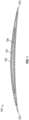
- FIG. 1 is an exemplary depiction of an airfoil 100 where none-shuffled ply stacking is used in the ply layup with a volume filling scheme. None-shuffled implies that the plies are not shuffled.
- the airfoil 100 has a leading edge 202 and a trailing edge 204 and the plies 102, 104, 106 are systematically distributed between the outer surface (suction surface) or the lower surface (pressure surface) of the airfoil and the central region of the airfoil. From the FIG.
- chordwise the largest plies 102 (chordwise) are located on the outer surfaces (the upper and lower camber) of the airfoil, while the smallest plies 106 (chordwise) are located at the interior, with the mid-sized plies 104 (chordwise) being distributed between the outermost plies and the innermost plies.
- the chord is a curve that that extends from the leading edge to the trailing edge and is at the mean of the pressure and suction side of the airfoil.
- chordwise implies a path along or parallel to the chord.
- This design has several drawbacks notably that concentration of short, small area, plies and long plies provides interlaminar crack paths that can propagate from the leading edge to the trailing edge or from the outer radius (tip) of the blade to the inner radius of the blade.
- concentration of short, small area, plies and long plies provides interlaminar crack paths that can propagate from the leading edge to the trailing edge or from the outer radius (tip) of the blade to the inner radius of the blade.
- the segregation of long plies to one portion of the airfoil and short plies to another part of the airfoil prevents the development of crack arresting mechanisms that can improve damage tolerance and mitigate crack initiation and growth.
- a fan blade that comprises interleaved plies, where interleaving comprises distributing wide plies amongst narrow plies in the fan blade.
- the interleaving is defined as an actual intersection of a plurality of plies of different variable dimensions that extend in the chordwise direction with another plurality of plies of different variable dimensions that extend in the spanwise direction such that their respective longitudinal axes intersect with one another at angles of 5 to 175 degrees.
- the wide plies and narrow plies are staggered chordwise with spanwise staggered long and short plies, or vice versa.
- interleaving comprises shuffling short plies with long plies in the spanwise direction, wide plies within narrow plies in the chordwise direction and thick plies with thin plies in the thickness direction to avoid segregating plies of one particular dimension from plies of another particular dimension.
- shuffling comprises splitting plies of different sizes and interspersing them in the fan blade such that there is no progressive dimensional sequencing of ply size in any one particular direction from a given ply in the fan blade.
- the interleaving is conducted so as to render delamination pathways more tortuous when compared with fan blades where there is no interleaving, thus reducing the speed at which delamination progresses.
- the angle of intersection between the respective longitudinal axes is 50 to 150 degrees.
- the angle of intersection between the respective longitudinal axes is 70 to 120 degrees.
- the interleaved plies comprise fibers that comprise silicon carbide, oxide ceramics and carbon.
- the interleaved plies comprise matrices that comprise SiC, Al 2 O 3 , BN, B 4 C, Si 3 N 4 , MoSi 2 , SiO 2 , SiOC, SiNC SiONC, or a combination thereof.
- the interleaved plies produce fewer regions of resin concentration relative to fan blades that that do not contain interleaved plies.
- a method of manufacturing a fan blade comprising shuffling plies in a fan blade prior to contacting the plies with one another such that they form interleaved plies.
- Interleaving comprises distributing wide plies within narrow plies and short plies within long plies in the fan blade.
- Interleaving is defined as an actual intersection of a plurality of plies of different variable dimensions that extend in the chordwise direction with another plurality of plies of different variable dimensions that extend in the spanwise direction such that their respective longitudinal axes intersect with one another at angles of 5 to 175 degrees.
- the interleaved plies are then consolidated and cured together to form the fan blade.
- shuffling comprises splitting plies of different sizes and interspersing them in the fan blade such that there is no progressive dimensional sequencing of ply size in any one particular direction from a given ply in the fan blade.
- bonding the interleaved plies comprises increasing the pressure and temperature on the plies.
- the shuffling is prescribed by a computer.
- interleaving comprises shuffling short plies with long plies in the spanwise direction, wide plies within narrow plies in the chordwise direction and thick plies with thin plies in the thickness direction to avoid segregating plies of one particular dimension from plies of another particular dimension.
- the interleaved plies produce fewer regions of resin concentration relative to fan blades that that do not contain interleaved plies.
- the angle of intersection between the respective longitudinal axes is 50 to 150 degrees.
- the angle of intersection between the respective longitudinal axes is 70 to 120 degrees.
- the method expands design space and manufacturing flexibility towards a goal of improving fan blade overall impact and mechanical performance.
- the method comprises shuffling plies chordwise and/or spanwise through the thickness (from pressure to suction sides) and the span (from outer diameter to inner radius) of the composite fan blade to distribute wide plies within narrow plies and short plies within long plies.
- shuffling includes splitting plies of different sizes and interspersing them in the fan blade such that there is no particular long range progressive dimensional (length, width and/or thickness) sequencing of ply size in any one particular direction from a given ply in the fan blade.
- Progressive dimensional sequencing implies that there is a gradual change in any particular dimension (length, width and/or thickness) in a particular direction.
- the first ply may be the widest
- the second ply adjacent the first ply may be a little narrower than the first ply
- the third ply adjacent the second ply may be narrower than the second ply.
- the fourth ply will be wider than at least the third ply.
- the fifth ply will be either wider than the fourth ply or narrower than the second ply.
- wide and narrow plies are re-staggered chordwise with the aforementioned spanwise long and short plies, or vice versa.
- the ability to shuffle long and short plies and re-stagger wide and narrow plies within the fan blade provides the designer with an ability to control the spatial dispersion of resin rich regions within the volume of an airfoil. It can facilitate avoidance of the creation of planes with accumulated undesirable features and improve overall interlaminar capabilities.
- the ply dimensions and location can be adjusted to balance material tensile strength at the outer surface and shear strength at mid-plane.
- delamination can be initiated and confined to certain local ply interfaces.
- the method comprises shuffling short plies with long plies in the spanwise direction, wide plies within narrow plies in the chordwise direction and thick plies with thin plies in the thickness direction to avoid segregating plies of one particular dimension from plies of another particular dimension.
- the segregation of plies often provides a clean delamination path leading from one surface of the wing to another surface (e.g., suction side to pressure side or to trailing edge, to leading edge).
- the pathway (of a crack) to a clean delamination is made tortuous thus preventing the crack from easily propagating and potentially leading to greater damage.
- the interleaving is conducted so as to render delamination pathways more tortuous when compared with fan blades where there is no interleaving, thus reducing the extent to which delamination (of plies) may progress.
- Layered structures define a wide variety of construction arrangements, including lightweight laminated composite articles.
- Laminated composites typically are defined by a continuous, essentially planar array of continuous fibers embedded in a matrix defining a lamina or ply, a plurality of plies forming a laminate composite. These composite articles can be arranged to meet various in-plane stiffness or strength needs by appropriate stacking of similar orthotropic plies of dissimilar orientation.
- Ceramic matrix composites generally comprise fibers that comprise silicon carbide, oxide ceramics, carbon, or a combination thereof.
- Exemplary matrix materials include SiC, Al 2 O 3 , BN, B 4 C, Si 3 N 4 , MoSi 2 , SiO 2 , SiOC, SiNC SiONC, or a combination thereof.
- An exemplary combination of fiber and matrix is silicon carbide fibers and a silicon carbide matrix.
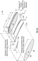
- FIGS. 2A , 2B and 2C are depictions of an exemplary composite fan blade 200 that details terms such as thicknesswise, chordwise and spanwise. These figures also attempt to show a basic example of the interleaving of plies.
- FIG. 2A provides a rough isometric view illustrating a layup that includes long and short plies (when viewed spanwise) interleaved with wide and narrow plies (when viewed chordwise).
- FIG. 2B is a chordwise view of interleaving, while FIG. 2B is a spanwise view of the interleaving.
- the fan blade 200 comprises a leading edge 202 and a trailing edge 204.
- the suction surface 206 is opposed to the pressure surface 208.
- Left wingtip 210 opposes right wingtip 212.
- the chord is an imaginary curve that extends from the leading edge to the trailing edge.
- chordwise implies a path along or parallel to the chord and is the direction in which ply width (W) is measured.
- the span is measured from outer diameter 210 to the inner diameter 212 in a radial direction.
- spanwise implies a path along or parallel to the span and is the direction along with length (L) of the ply is measured.
- the thickness is measured from the suction surface 206 to pressure surface 208 and the term "thicknesswise" implies a path from the upper surface to the lower surface along which thickness (T) is measured.
- thickness (T) is measured perpendicular to the other two dimensions.
- thickness (T) is measured from suction surface to the pressure surface in a direction that is perpendicular to the chord and the span.
- the fan blade 200 comprises a first ply 302 having a first width W 1 and length L 1 is disposed atop a second ply 304 having a second width W 2 and length L 2 , such that W 1 is less than W 2 and L 1 is greater than L 2 .
- a third ply 306 having width W 3 and length L 3 is disposed adjacent the first ply 302 and atop the second ply 304 such that W 3 is smaller than W 1 and W 2 , but L 3 is greater than L 1 an L 2 .
- This thickness of the plies are also different from one another.
- the first ply has a thickness T 1 that is greater than the thickness T 2 but less than the thickness T 3 .
- FIGS. 2B and 2C depict a chordwise and spanwise views respectively of interleaved plies to enable a clearer definition of interleaving.
- FIG. 2B shows plies 310, 312 and 316 that have widths that are greater than their lengths.
- Ply 310 has a width W 2
- ply 312 has a width W 1
- ply 316 has a width W 3 with W 3 >W 2 >W 1 .
- the plies 310, 312 and 316 share longitudinal axis AA'.
- the length of each of these plies is L 3 and is measured spanwise, while the widths W 1 , W 2 and W 3 are measured chordwise. From the FIG.
- plies 410 and 412 have lengths L 1 and L 2 respectively measured in the spanwise direction that are greater than their widths W 5 and W 4 respectively measured in the chordwise direction.
- Plies 410 and 412 have longitudinal axes BB' and CC' respectively that are inclined at an angle ⁇ with respect to the longitudinal axis AA' of the plies 310, 312 and 316.
- the angle ⁇ is then angle between the longitudinal axes of plies that extend in the chordwise direction with the longitudinal axes of plies that extend in the spanwise direction.
- the angle ⁇ may vary between 5 degrees and 175 degrees, preferably 50 degrees to 150 degrees.
- a tortuous path is one that weaves back and forth because it is obstructed by plies that have been deliberately put in its path to prevent it from traveling uniformly in one direction.
- the tortuous path makes at least one change in direction of at least 90 degrees, preferably at least 120 degrees, and more preferably at least 150 degrees.
- the shuffling of plies by interspersing short plies with long plies provides the composite fan blade with a "rest” or “braking” mechanism where delamination (in the form of crack propagation) is suppressed when it beings to propagate thicknesswise, chordwise, spanwise, or in a combination of directions thereof.
- delamination in the form of crack propagation
- This method of arresting or mitigating crack propagation has the potential to increase damage tolerance of the fan blade under impact events including bird strike, fan blade-out, ice and hail conditions.
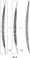
- FIG. 3A depicts one exemplary method of shuffling of the wide and narrow plies within the composite fan blade.
- FIG. 3A represents a chordwise view of the same fan blade as the series of shuffles are made.
- the leading edge is denoted by LE while the trailing edge is denoted by TE.
- the arrows point to each incremental change in the interleaving of the plies with each shuffle.
- the progression in interleaving is indicated by cross-sectional views 3A1 through 3A4, with 3A1 being the fan blade without interleaving due to shuffling, while 3A4 is the fan blade after the last shuffle.
- FIGS. 3A3 and 3A4 are shown again in expanded view for the benefit of the reader.
- the suction surface 600 and the pressure surface 700 contact each other at the leading edge and trailing edge of the fan blade.
- the suction surface 600 and the pressure surface 700 comprise the widest plies 502A and 502B respectively.
- the plies are sequentially arranged with the widest ply lying next to an intermediate ply, which lies next to the narrowest ply. Shuffling promotes a change in this size wise sequential distribution of the plies.
- the plies after shuffling staggered with no large size sequences (by ply size) in the fan blade.
- the narrowest ply is 30 to 70% of the size of the widest ply, while an intermediate ply is always wider than the narrowest ply and has a length that varies from 40 to 80% of the width of the widest ply.
- a composite fan blade may contain plies having 5 or more different lengths of plies based on the length of the widest ply.
- the Table below indicates 10 plies of different sizes based on the length (width) of the widest ply.
- the widest ply is Ply #10
- the narrowest ply is Ply # 1 in the Table. All 10 plies indicated in the Table below do not have to be used in a composite. Any combination of 2 or more plies of different lengths from the Table may be used and shuffled as desired to produce the best resistance to stress and delamination.
- Ply # Width as a percentage of widest ply (Ply #10) Ply #1 (narrowest ply) 10 to 30 Ply #2 (longer than ply #1) 10 to 35, preferably 15 to 32 Ply #3 (longer than ply #2) 10 to 40, preferably 17 to 38 Ply #4 (longer than ply #3) 10 to 50, preferably 20 to 45 Ply #5 (longer than ply #4) 10 to 60, preferably 25 to 55 Ply #6 (longer than ply #5) 10 to 70, preferably 28 to 65 Ply #7 (longer than ply #6) 10 to 80, preferably 35 to 75 Ply #8 (longer than ply #6) 10 to 85, preferably 45 to 82 Ply #9 (longer than ply #6) 10 to 90, preferably 48 to 88 Ply # 10 (widestply) 100
- the dimensions pertaining to ply size in the Table refer to the width of the plies, it can apply to any dimension such as, for example, length or thickness.
- the dimension of the smallest ply can be expressed as a percentage of that dimension of the longest ply - and that dimension can be width, length or thickness.
- a portion of the widest plies 502A and 502B are shuffled to be in the center of the narrowest plies 506, splitting the narrowest plies 506 into two domains 506A and 506B that contact the opposing surface of the newest portion of the widest plies 502C.
- the thickness of the widest plies 502A and 502B are reduced by the amount of ply material used in 502C, while the original central region 506 is now split into two regions 506A and 506B.
- the combined thickness of 506A and 506B is equal to that of the original central region 506. With each shuffle, the thickness of the original plies is reduced.
- the intermediate plies 504A and 504B are split (shuffled) into two more plies 504C and 504D that are disposed on and contact the widest ply 502C located in the center of the fan blade.
- the widest plies 502A, 502B and 502C are also split into two additional plies 502D and 502E that are dispersed amongst the narrowest plies 506A and 506B to produce plies 506C and 506D.
- a previously existing thicker ply is narrowed and interspersed amongst plies of a different length. This as can be seen from the FIG.
- the various plies detailed in sequence from the suction surface 600 to pressure surface 700 are widest ply 502A, intermediate ply 504A, narrowest ply 506A, widest ply 502D, narrowest ply 506C, intermediate ply 504C, widest ply 502C, intermediate ply 504D, narrowest ply 506D, widest ply 502E, narrowest ply 506E, intermediate ply 504B and widest ply 502B.
- FIG. 3A (3A4) reflects one more shuffle and a greater mixing of the plies of different sizes.
- the order of the plies will not be detailed one more time, but the reader can garner that there is a greater dispersion of plies of different sizes amongst one another.
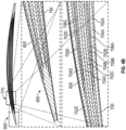
- FIGS. 4A and 4B show how shuffling disperses not only the plies but also the boundary between plies.
- FIG. 4A depicts the prior art arrangement of plies in a conventional method of manufacturing the fan blade while FIG. 4B depicts the arrangement of plies and the boundary between plies when subjected to shuffling.
- FIG. 4A depicts a portion of fan blade (viewed chordwise) proximate to the leading edge (LE) with suction surface 150 and pressure surface 152.
- FIG. 4A depicts two enlarged sections 160 and 170 of the fan blade.
- the section 160 depicts the region around the leading edge (LE) of the fan blade, while the section 170 depicts the region proximate to the leading edge. From the two enlarged sections 160 and 170 it can be seen that disposed between the upper camber 150 and the lower camber 152 are a series of plies, notably the widest ply 102, the intermediate ply 104 and the narrowest ply 106 (See FIG. 1 for details).
- FIG. 4B depicts a portion of the fan blade 800 (viewed chordwise) proximate to the leading edge (LE) having upper camber 600 and loser camber 700 with interleaved plies contained therebetween.
- the FIG. 4B depicts two enlarged views 660 and 760 of the fan blade.
- View 660 is an enlarged sectional view of the region near the leading edge (LE), while view 760 depicts a section of the fan blade proximate to the leading edge.
- the interleaved plies are arranged as previously described in FIG. 3B (see views 3B3 and 3B4) and the interleaving process will not be detailed here once again. From the FIG.
- the plies are interleaved (in sequence) as follows - widest ply 702A, intermediate ply 704A, narrowest ply 706A, widest ply 702B, narrowest ply 706B, intermediate ply 704B, widest ply 702C, intermediate ply 704C, narrowest ply 706C, widest ply 702D, narrowest ply 706D, intermediate ply 704D and widest ply 702E.
- the ply drops (the resin rich regions) are spaced out and not aligned thus offering a crack an easy path of propagation which can eventually lead to complete delamination of a portion of the fan blade.
- the presence of a continuous ply 702C prevents the presence of a ply drop, which prevents the delamination of the fan blade.
- the interleaving of plies causes resin concentration to be reduced when compared with fan blades where there is no interleaving.
- one manner of manufacturing the fan blade comprises shuffling plies in a fan blade prior to contacting the plies with one another such that they form interleaved plies.
- interleaving comprises distributing wide plies within narrow plies and short plies within long plies in the fan blade.
- the interleaving is defined as an actual intersection of a plurality of plies of different variable dimensions that extend in the chordwise direction with another plurality of plies of different variable dimensions that extend in the spanwise direction such that their respective longitudinal axes intersect with one another at angles of 5 to 175 degrees.
- the interleaved plies are cured in an autoclave or similar device.
- the shuffling of the plies and the positional sequences may be prescribed by a computer.
- the interleaving of plies caused by shuffling extends the robustness of the fan blades because they create obstructions in the path of crack propagation.
- the presence of resin rich regions that offer fertile pathways for delamination are minimized.
- the plies can be interleaved to obtain a better balance of stress distribution across the fan blade.
- blade robustness is improved as measured by the extent of delamination when compared with a fan blade of the same dimensions that does not contain interleaved plies.
Landscapes
- Engineering & Computer Science (AREA)
- Chemical & Material Sciences (AREA)
- Materials Engineering (AREA)
- Mechanical Engineering (AREA)
- General Engineering & Computer Science (AREA)
- Composite Materials (AREA)
- Architecture (AREA)
- Structures Of Non-Positive Displacement Pumps (AREA)
Applications Claiming Priority (1)
| Application Number | Priority Date | Filing Date | Title |
|---|---|---|---|
| US202163230506P | 2021-08-06 | 2021-08-06 |
Publications (2)
| Publication Number | Publication Date |
|---|---|
| EP4130431A1 true EP4130431A1 (de) | 2023-02-08 |
| EP4130431B1 EP4130431B1 (de) | 2024-11-27 |
Family
ID=82850422
Family Applications (1)
| Application Number | Title | Priority Date | Filing Date |
|---|---|---|---|
| EP22189343.1A Active EP4130431B1 (de) | 2021-08-06 | 2022-08-08 | Verbundwerkstoff-fanschaufelblatt und verfahren zu dessen herstellung |
Country Status (2)
| Country | Link |
|---|---|
| US (1) | US11927113B2 (de) |
| EP (1) | EP4130431B1 (de) |
Families Citing this family (1)
| Publication number | Priority date | Publication date | Assignee | Title |
|---|---|---|---|---|
| US12448897B2 (en) * | 2024-01-31 | 2025-10-21 | Rtx Corporation | Gas turbine engine component formed by CMCS and having a compressed insert with tapered ends |
Citations (7)
| Publication number | Priority date | Publication date | Assignee | Title |
|---|---|---|---|---|
| US5375978A (en) * | 1992-05-01 | 1994-12-27 | General Electric Company | Foreign object damage resistant composite blade and manufacture |
| EP2149711A2 (de) * | 2008-07-31 | 2010-02-03 | General Electric Company | Herstellungsverfahren für eine Gebläseschaufel einer Strömungsmaschine |
| EP2299123A2 (de) * | 2009-09-02 | 2011-03-23 | United Technologies Corporation | Verbundschaufelblatt mit lokal verstärkten Blattspitzenabschnitten |
| US20110176927A1 (en) * | 2010-01-20 | 2011-07-21 | United Technologies Corporation | Composite fan blade |
| US20180094525A1 (en) * | 2016-10-04 | 2018-04-05 | General Electric Company | Methods and features for cmc component repairs |
| US20180216477A1 (en) * | 2017-02-01 | 2018-08-02 | General Electric Company | Preform cmc article, cmc article, and method for forming cmc article |
| EP3517732A1 (de) * | 2018-01-29 | 2019-07-31 | General Electric Company | Verstärkte verbundschaufel und verfahren zur herstellung einer schaufel |
Family Cites Families (5)
| Publication number | Priority date | Publication date | Assignee | Title |
|---|---|---|---|---|
| US9169728B2 (en) * | 2011-12-08 | 2015-10-27 | General Electric Company | Dynamic load reduction system |
| US10654246B2 (en) | 2012-04-28 | 2020-05-19 | General Electric Company | Composite article and methods therefor |
| GB2549508B (en) | 2016-04-20 | 2019-06-19 | Rolls Royce Plc | Gas turbine engine |
| US10830062B2 (en) | 2018-03-20 | 2020-11-10 | Raytheon Technologies Corporation | Single ply having plurality of fiber angles |
| US11519282B2 (en) * | 2019-11-11 | 2022-12-06 | Raytheon Technologies Corporation | Ceramic matrix composite-based seal |
-
2022
- 2022-08-05 US US17/881,954 patent/US11927113B2/en active Active
- 2022-08-08 EP EP22189343.1A patent/EP4130431B1/de active Active
Patent Citations (7)
| Publication number | Priority date | Publication date | Assignee | Title |
|---|---|---|---|---|
| US5375978A (en) * | 1992-05-01 | 1994-12-27 | General Electric Company | Foreign object damage resistant composite blade and manufacture |
| EP2149711A2 (de) * | 2008-07-31 | 2010-02-03 | General Electric Company | Herstellungsverfahren für eine Gebläseschaufel einer Strömungsmaschine |
| EP2299123A2 (de) * | 2009-09-02 | 2011-03-23 | United Technologies Corporation | Verbundschaufelblatt mit lokal verstärkten Blattspitzenabschnitten |
| US20110176927A1 (en) * | 2010-01-20 | 2011-07-21 | United Technologies Corporation | Composite fan blade |
| US20180094525A1 (en) * | 2016-10-04 | 2018-04-05 | General Electric Company | Methods and features for cmc component repairs |
| US20180216477A1 (en) * | 2017-02-01 | 2018-08-02 | General Electric Company | Preform cmc article, cmc article, and method for forming cmc article |
| EP3517732A1 (de) * | 2018-01-29 | 2019-07-31 | General Electric Company | Verstärkte verbundschaufel und verfahren zur herstellung einer schaufel |
Also Published As
| Publication number | Publication date |
|---|---|
| US20230051131A1 (en) | 2023-02-16 |
| EP4130431B1 (de) | 2024-11-27 |
| US11927113B2 (en) | 2024-03-12 |
Similar Documents
| Publication | Publication Date | Title |
|---|---|---|
| JP7584563B2 (ja) | 複合翼のための外板/ストリンガ設計 | |
| CN107878726B (zh) | 先进的可变半径层压式复合材料半径填料 | |
| CN110094237B (zh) | 增强的复合叶片及制作叶片的方法 | |
| EP1666353B1 (de) | Verfahren zur Herstellung eines gekrümmten Trägers aus Verbundwerkstoff | |
| JP6247048B2 (ja) | 航空機の接合式複合材翼 | |
| US7338694B2 (en) | Method for an integral composite forward flange in a composite | |
| CN116710633B (zh) | 风扇叶片的纤维增强件中的纤维的混合 | |
| EP2415665B1 (de) | Rotorblatt | |
| CN103038052A (zh) | 用于宇航飞行器的复合材料加劲肋 | |
| US20120263913A1 (en) | Wing and blade structure using pultruded composites | |
| US20230040244A1 (en) | Composite fan blade airfoil, methods of manufacture thereof and articles comprising the same | |
| US20110143081A1 (en) | Modified ply drops for composite laminate materials | |
| JP7336202B2 (ja) | 中実積層ストリンガ | |
| JP6021815B2 (ja) | 積層構造体 | |
| EP4130431A1 (de) | Verbundwerkstoff-schaufelblatt und verfahren zu dessen herstellung | |
| US20200102968A1 (en) | Gas turbine engine | |
| CN102862299B (zh) | 层状复合部件 | |
| US9126671B2 (en) | Stiff panel for aircraft, comprising stiffeners with notched cores | |
| EP2955005B1 (de) | Verbundstruktur und verfahren zur herstellung davon | |
| JP7175624B2 (ja) | セラミックマトリックス複合材(cmc)タービンブレードおよびcmcタービンブレードを形成する方法 | |
| US11685503B2 (en) | Stringer assemblies and methods of forming thereof | |
| CN115052740B (zh) | 有限尺寸的复合层压插片、由其形成的渐缩复合层压结构及其制造和使用方法 | |
| MJ et al. | Influence of intralaminar discontinuity distribution on mechanical properties and damage evolution of unidirectional CFRP laminates | |
| GB2639409A (en) | Composite blade |
Legal Events
| Date | Code | Title | Description |
|---|---|---|---|
| PUAI | Public reference made under article 153(3) epc to a published international application that has entered the european phase |
Free format text: ORIGINAL CODE: 0009012 |
|
| STAA | Information on the status of an ep patent application or granted ep patent |
Free format text: STATUS: THE APPLICATION HAS BEEN PUBLISHED |
|
| AK | Designated contracting states |
Kind code of ref document: A1 Designated state(s): AL AT BE BG CH CY CZ DE DK EE ES FI FR GB GR HR HU IE IS IT LI LT LU LV MC MK MT NL NO PL PT RO RS SE SI SK SM TR |
|
| STAA | Information on the status of an ep patent application or granted ep patent |
Free format text: STATUS: REQUEST FOR EXAMINATION WAS MADE |
|
| 17P | Request for examination filed |
Effective date: 20230807 |
|
| RBV | Designated contracting states (corrected) |
Designated state(s): AL AT BE BG CH CY CZ DE DK EE ES FI FR GB GR HR HU IE IS IT LI LT LU LV MC MK MT NL NO PL PT RO RS SE SI SK SM TR |
|
| RAP3 | Party data changed (applicant data changed or rights of an application transferred) |
Owner name: RTX CORPORATION |
|
| RIC1 | Information provided on ipc code assigned before grant |
Ipc: F01D 5/28 20060101ALI20240405BHEP Ipc: F01D 5/14 20060101AFI20240405BHEP |
|
| GRAP | Despatch of communication of intention to grant a patent |
Free format text: ORIGINAL CODE: EPIDOSNIGR1 |
|
| STAA | Information on the status of an ep patent application or granted ep patent |
Free format text: STATUS: GRANT OF PATENT IS INTENDED |
|
| INTG | Intention to grant announced |
Effective date: 20240619 |
|
| GRAS | Grant fee paid |
Free format text: ORIGINAL CODE: EPIDOSNIGR3 |
|
| GRAA | (expected) grant |
Free format text: ORIGINAL CODE: 0009210 |
|
| STAA | Information on the status of an ep patent application or granted ep patent |
Free format text: STATUS: THE PATENT HAS BEEN GRANTED |
|
| AK | Designated contracting states |
Kind code of ref document: B1 Designated state(s): AL AT BE BG CH CY CZ DE DK EE ES FI FR GB GR HR HU IE IS IT LI LT LU LV MC MK MT NL NO PL PT RO RS SE SI SK SM TR |
|
| REG | Reference to a national code |
Ref country code: GB Ref legal event code: FG4D |
|
| REG | Reference to a national code |
Ref country code: CH Ref legal event code: EP |
|
| REG | Reference to a national code |
Ref country code: IE Ref legal event code: FG4D |
|
| REG | Reference to a national code |
Ref country code: DE Ref legal event code: R096 Ref document number: 602022008123 Country of ref document: DE |
|
| REG | Reference to a national code |
Ref country code: LT Ref legal event code: MG9D |
|
| REG | Reference to a national code |
Ref country code: NL Ref legal event code: MP Effective date: 20241127 |
|
| PG25 | Lapsed in a contracting state [announced via postgrant information from national office to epo] |
Ref country code: IS Free format text: LAPSE BECAUSE OF FAILURE TO SUBMIT A TRANSLATION OF THE DESCRIPTION OR TO PAY THE FEE WITHIN THE PRESCRIBED TIME-LIMIT Effective date: 20250327 Ref country code: PT Free format text: LAPSE BECAUSE OF FAILURE TO SUBMIT A TRANSLATION OF THE DESCRIPTION OR TO PAY THE FEE WITHIN THE PRESCRIBED TIME-LIMIT Effective date: 20250327 Ref country code: HR Free format text: LAPSE BECAUSE OF FAILURE TO SUBMIT A TRANSLATION OF THE DESCRIPTION OR TO PAY THE FEE WITHIN THE PRESCRIBED TIME-LIMIT Effective date: 20241127 |
|
| PG25 | Lapsed in a contracting state [announced via postgrant information from national office to epo] |
Ref country code: FI Free format text: LAPSE BECAUSE OF FAILURE TO SUBMIT A TRANSLATION OF THE DESCRIPTION OR TO PAY THE FEE WITHIN THE PRESCRIBED TIME-LIMIT Effective date: 20241127 Ref country code: NL Free format text: LAPSE BECAUSE OF FAILURE TO SUBMIT A TRANSLATION OF THE DESCRIPTION OR TO PAY THE FEE WITHIN THE PRESCRIBED TIME-LIMIT Effective date: 20241127 |
|
| REG | Reference to a national code |
Ref country code: AT Ref legal event code: MK05 Ref document number: 1745875 Country of ref document: AT Kind code of ref document: T Effective date: 20241127 |
|
| PG25 | Lapsed in a contracting state [announced via postgrant information from national office to epo] |
Ref country code: BG Free format text: LAPSE BECAUSE OF FAILURE TO SUBMIT A TRANSLATION OF THE DESCRIPTION OR TO PAY THE FEE WITHIN THE PRESCRIBED TIME-LIMIT Effective date: 20241127 |
|
| PG25 | Lapsed in a contracting state [announced via postgrant information from national office to epo] |
Ref country code: ES Free format text: LAPSE BECAUSE OF FAILURE TO SUBMIT A TRANSLATION OF THE DESCRIPTION OR TO PAY THE FEE WITHIN THE PRESCRIBED TIME-LIMIT Effective date: 20241127 |
|
| PG25 | Lapsed in a contracting state [announced via postgrant information from national office to epo] |
Ref country code: NO Free format text: LAPSE BECAUSE OF FAILURE TO SUBMIT A TRANSLATION OF THE DESCRIPTION OR TO PAY THE FEE WITHIN THE PRESCRIBED TIME-LIMIT Effective date: 20250227 |
|
| PG25 | Lapsed in a contracting state [announced via postgrant information from national office to epo] |
Ref country code: LV Free format text: LAPSE BECAUSE OF FAILURE TO SUBMIT A TRANSLATION OF THE DESCRIPTION OR TO PAY THE FEE WITHIN THE PRESCRIBED TIME-LIMIT Effective date: 20241127 Ref country code: GR Free format text: LAPSE BECAUSE OF FAILURE TO SUBMIT A TRANSLATION OF THE DESCRIPTION OR TO PAY THE FEE WITHIN THE PRESCRIBED TIME-LIMIT Effective date: 20250228 Ref country code: AT Free format text: LAPSE BECAUSE OF FAILURE TO SUBMIT A TRANSLATION OF THE DESCRIPTION OR TO PAY THE FEE WITHIN THE PRESCRIBED TIME-LIMIT Effective date: 20241127 |
|
| PG25 | Lapsed in a contracting state [announced via postgrant information from national office to epo] |
Ref country code: PL Free format text: LAPSE BECAUSE OF FAILURE TO SUBMIT A TRANSLATION OF THE DESCRIPTION OR TO PAY THE FEE WITHIN THE PRESCRIBED TIME-LIMIT Effective date: 20241127 |
|
| PG25 | Lapsed in a contracting state [announced via postgrant information from national office to epo] |
Ref country code: RS Free format text: LAPSE BECAUSE OF FAILURE TO SUBMIT A TRANSLATION OF THE DESCRIPTION OR TO PAY THE FEE WITHIN THE PRESCRIBED TIME-LIMIT Effective date: 20250227 |
|
| PG25 | Lapsed in a contracting state [announced via postgrant information from national office to epo] |
Ref country code: SM Free format text: LAPSE BECAUSE OF FAILURE TO SUBMIT A TRANSLATION OF THE DESCRIPTION OR TO PAY THE FEE WITHIN THE PRESCRIBED TIME-LIMIT Effective date: 20241127 |
|
| PG25 | Lapsed in a contracting state [announced via postgrant information from national office to epo] |
Ref country code: DK Free format text: LAPSE BECAUSE OF FAILURE TO SUBMIT A TRANSLATION OF THE DESCRIPTION OR TO PAY THE FEE WITHIN THE PRESCRIBED TIME-LIMIT Effective date: 20241127 |
|
| PG25 | Lapsed in a contracting state [announced via postgrant information from national office to epo] |
Ref country code: EE Free format text: LAPSE BECAUSE OF FAILURE TO SUBMIT A TRANSLATION OF THE DESCRIPTION OR TO PAY THE FEE WITHIN THE PRESCRIBED TIME-LIMIT Effective date: 20241127 |
|
| PG25 | Lapsed in a contracting state [announced via postgrant information from national office to epo] |
Ref country code: RO Free format text: LAPSE BECAUSE OF FAILURE TO SUBMIT A TRANSLATION OF THE DESCRIPTION OR TO PAY THE FEE WITHIN THE PRESCRIBED TIME-LIMIT Effective date: 20241127 |
|
| PG25 | Lapsed in a contracting state [announced via postgrant information from national office to epo] |
Ref country code: SK Free format text: LAPSE BECAUSE OF FAILURE TO SUBMIT A TRANSLATION OF THE DESCRIPTION OR TO PAY THE FEE WITHIN THE PRESCRIBED TIME-LIMIT Effective date: 20241127 |
|
| PG25 | Lapsed in a contracting state [announced via postgrant information from national office to epo] |
Ref country code: CZ Free format text: LAPSE BECAUSE OF FAILURE TO SUBMIT A TRANSLATION OF THE DESCRIPTION OR TO PAY THE FEE WITHIN THE PRESCRIBED TIME-LIMIT Effective date: 20241127 |
|
| PG25 | Lapsed in a contracting state [announced via postgrant information from national office to epo] |
Ref country code: IT Free format text: LAPSE BECAUSE OF FAILURE TO SUBMIT A TRANSLATION OF THE DESCRIPTION OR TO PAY THE FEE WITHIN THE PRESCRIBED TIME-LIMIT Effective date: 20241127 |
|
| REG | Reference to a national code |
Ref country code: DE Ref legal event code: R097 Ref document number: 602022008123 Country of ref document: DE |
|
| PG25 | Lapsed in a contracting state [announced via postgrant information from national office to epo] |
Ref country code: SE Free format text: LAPSE BECAUSE OF FAILURE TO SUBMIT A TRANSLATION OF THE DESCRIPTION OR TO PAY THE FEE WITHIN THE PRESCRIBED TIME-LIMIT Effective date: 20241127 |
|
| PLBE | No opposition filed within time limit |
Free format text: ORIGINAL CODE: 0009261 |
|
| STAA | Information on the status of an ep patent application or granted ep patent |
Free format text: STATUS: NO OPPOSITION FILED WITHIN TIME LIMIT |
|
| REG | Reference to a national code |
Ref country code: CH Ref legal event code: L10 Free format text: ST27 STATUS EVENT CODE: U-0-0-L10-L00 (AS PROVIDED BY THE NATIONAL OFFICE) Effective date: 20251008 |
|
| PGFP | Annual fee paid to national office [announced via postgrant information from national office to epo] |
Ref country code: DE Payment date: 20250724 Year of fee payment: 4 |
|
| PGFP | Annual fee paid to national office [announced via postgrant information from national office to epo] |
Ref country code: FR Payment date: 20250725 Year of fee payment: 4 |
|
| 26N | No opposition filed |
Effective date: 20250828 |
|
| REG | Reference to a national code |
Ref country code: CH Ref legal event code: H13 Free format text: ST27 STATUS EVENT CODE: U-0-0-H10-H13 (AS PROVIDED BY THE NATIONAL OFFICE) Effective date: 20260324 |
|
| PG25 | Lapsed in a contracting state [announced via postgrant information from national office to epo] |
Ref country code: MC Free format text: LAPSE BECAUSE OF FAILURE TO SUBMIT A TRANSLATION OF THE DESCRIPTION OR TO PAY THE FEE WITHIN THE PRESCRIBED TIME-LIMIT Effective date: 20241127 |
|
| PG25 | Lapsed in a contracting state [announced via postgrant information from national office to epo] |
Ref country code: LU Free format text: LAPSE BECAUSE OF NON-PAYMENT OF DUE FEES Effective date: 20250808 |
|
| PG25 | Lapsed in a contracting state [announced via postgrant information from national office to epo] |
Ref country code: CH Free format text: LAPSE BECAUSE OF NON-PAYMENT OF DUE FEES Effective date: 20250831 |