EP4130471A1 - Pompe à piston alternatif - Google Patents
Pompe à piston alternatif Download PDFInfo
- Publication number
- EP4130471A1 EP4130471A1 EP22188558.5A EP22188558A EP4130471A1 EP 4130471 A1 EP4130471 A1 EP 4130471A1 EP 22188558 A EP22188558 A EP 22188558A EP 4130471 A1 EP4130471 A1 EP 4130471A1
- Authority
- EP
- European Patent Office
- Prior art keywords
- piston
- cam
- casing
- reciprocating pump
- lever arm
- Prior art date
- Legal status (The legal status is an assumption and is not a legal conclusion. Google has not performed a legal analysis and makes no representation as to the accuracy of the status listed.)
- Granted
Links
Images


Classifications
-
- F—MECHANICAL ENGINEERING; LIGHTING; HEATING; WEAPONS; BLASTING
- F04—POSITIVE - DISPLACEMENT MACHINES FOR LIQUIDS; PUMPS FOR LIQUIDS OR ELASTIC FLUIDS
- F04B—POSITIVE-DISPLACEMENT MACHINES FOR LIQUIDS; PUMPS
- F04B43/00—Machines, pumps, or pumping installations having flexible working members
- F04B43/02—Machines, pumps, or pumping installations having flexible working members having plate-like flexible members, e.g. diaphragms
- F04B43/025—Machines, pumps, or pumping installations having flexible working members having plate-like flexible members, e.g. diaphragms two or more plate-like pumping members in parallel
- F04B43/026—Machines, pumps, or pumping installations having flexible working members having plate-like flexible members, e.g. diaphragms two or more plate-like pumping members in parallel each plate-like pumping flexible member working in its own pumping chamber
-
- F—MECHANICAL ENGINEERING; LIGHTING; HEATING; WEAPONS; BLASTING
- F04—POSITIVE - DISPLACEMENT MACHINES FOR LIQUIDS; PUMPS FOR LIQUIDS OR ELASTIC FLUIDS
- F04B—POSITIVE-DISPLACEMENT MACHINES FOR LIQUIDS; PUMPS
- F04B1/00—Multi-cylinder machines or pumps characterised by number or arrangement of cylinders
- F04B1/04—Multi-cylinder machines or pumps characterised by number or arrangement of cylinders having cylinders in star- or fan-arrangement
- F04B1/0404—Details or component parts
- F04B1/0426—Arrangements for pressing the pistons against the actuated cam; Arrangements for connecting the pistons to the actuated cam
-
- F—MECHANICAL ENGINEERING; LIGHTING; HEATING; WEAPONS; BLASTING
- F04—POSITIVE - DISPLACEMENT MACHINES FOR LIQUIDS; PUMPS FOR LIQUIDS OR ELASTIC FLUIDS
- F04B—POSITIVE-DISPLACEMENT MACHINES FOR LIQUIDS; PUMPS
- F04B1/00—Multi-cylinder machines or pumps characterised by number or arrangement of cylinders
- F04B1/04—Multi-cylinder machines or pumps characterised by number or arrangement of cylinders having cylinders in star- or fan-arrangement
- F04B1/0404—Details or component parts
- F04B1/0439—Supporting or guiding means for the pistons
-
- F—MECHANICAL ENGINEERING; LIGHTING; HEATING; WEAPONS; BLASTING
- F04—POSITIVE - DISPLACEMENT MACHINES FOR LIQUIDS; PUMPS FOR LIQUIDS OR ELASTIC FLUIDS
- F04B—POSITIVE-DISPLACEMENT MACHINES FOR LIQUIDS; PUMPS
- F04B1/00—Multi-cylinder machines or pumps characterised by number or arrangement of cylinders
- F04B1/04—Multi-cylinder machines or pumps characterised by number or arrangement of cylinders having cylinders in star- or fan-arrangement
- F04B1/047—Multi-cylinder machines or pumps characterised by number or arrangement of cylinders having cylinders in star- or fan-arrangement with actuating or actuated elements at the outer ends of the cylinders
-
- F—MECHANICAL ENGINEERING; LIGHTING; HEATING; WEAPONS; BLASTING
- F04—POSITIVE - DISPLACEMENT MACHINES FOR LIQUIDS; PUMPS FOR LIQUIDS OR ELASTIC FLUIDS
- F04B—POSITIVE-DISPLACEMENT MACHINES FOR LIQUIDS; PUMPS
- F04B43/00—Machines, pumps, or pumping installations having flexible working members
- F04B43/02—Machines, pumps, or pumping installations having flexible working members having plate-like flexible members, e.g. diaphragms
-
- F—MECHANICAL ENGINEERING; LIGHTING; HEATING; WEAPONS; BLASTING
- F04—POSITIVE - DISPLACEMENT MACHINES FOR LIQUIDS; PUMPS FOR LIQUIDS OR ELASTIC FLUIDS
- F04B—POSITIVE-DISPLACEMENT MACHINES FOR LIQUIDS; PUMPS
- F04B9/00—Piston machines or pumps characterised by the driving or driven means to or from their working members
- F04B9/02—Piston machines or pumps characterised by the driving or driven means to or from their working members the means being mechanical
- F04B9/04—Piston machines or pumps characterised by the driving or driven means to or from their working members the means being mechanical the means being cams, eccentrics or pin-and-slot mechanisms
- F04B9/042—Piston machines or pumps characterised by the driving or driven means to or from their working members the means being mechanical the means being cams, eccentrics or pin-and-slot mechanisms the means being cams
-
- F—MECHANICAL ENGINEERING; LIGHTING; HEATING; WEAPONS; BLASTING
- F04—POSITIVE - DISPLACEMENT MACHINES FOR LIQUIDS; PUMPS FOR LIQUIDS OR ELASTIC FLUIDS
- F04B—POSITIVE-DISPLACEMENT MACHINES FOR LIQUIDS; PUMPS
- F04B9/00—Piston machines or pumps characterised by the driving or driven means to or from their working members
- F04B9/02—Piston machines or pumps characterised by the driving or driven means to or from their working members the means being mechanical
- F04B9/04—Piston machines or pumps characterised by the driving or driven means to or from their working members the means being mechanical the means being cams, eccentrics or pin-and-slot mechanisms
- F04B9/045—Piston machines or pumps characterised by the driving or driven means to or from their working members the means being mechanical the means being cams, eccentrics or pin-and-slot mechanisms the means being eccentrics
Definitions
- the present pump is intended to be advantageously employed in the attainment of volumetric pumps, in particular of membrane and multiple head type.
- the present reciprocating pump is inserted in the industrial field of production of pumps for farming machinery and is in particular intended to be employed for picking up a fluid from a source, for example a cistern transported by the farming machinery, and for conveying the aforesaid fluid under pressure to a plurality of dispensing nozzles, so as to irrigate or disinfesting cultivations.
- a source for example a cistern transported by the farming machinery
- dispensing nozzles so as to irrigate or disinfesting cultivations.
- the present reciprocating pump is therefore employable for example in the agriculture field for irrigation or disinfestation of the cultivations, or also in any other field of the art where it is necessary to pump large quantities of liquid.
- the membranes of the heads of the reciprocating pump are moved by actuation means housed inside the casing.
- the aforesaid actuation means are provided with a circular cam, mounted eccentric on a shaft that is actuatable in rotation, and with a thrust arm, extended between a first end having an annular connection body rotatably mounted on the cam and an opposite second end connected to a piston slidable in a corresponding guide jacket in order to move the membrane.
- the main drawback lies in the fact that the eccentric circular cam and the thrust arm are associable with a mechanism of connecting rod-crank type, which is capable of moving the piston connected to the membrane only and exclusively with harmonic motion along the guide jacket.
- the guide channel of the cam is provided with a first lateral surface directed in the direction opposite the rotation axis of the cam itself, which is arranged for pushing, through the cam follower, the corresponding piston to reduce the volume of the pumping chamber, and with a second lateral surface facing the first and directed towards the rotation axis, which is arranged in order to return the piston, always through the cam follower thereof, to expand the volume of the pumping chamber.
- the first lateral surface of the guide channel is capable of pushing the piston away from the rotation axis of the cam for at least one or more corresponding first angular sections of the cam around the rotation axis thereof and the second lateral surface is capable of returning the piston towards the rotation axis for one or more corresponding second angular sections of the same cam around the rotation axis, and such second angular sections are explementary to the first angular sections. Therefore, the guide channel made in depression on the cam can be shaped in a manner such to impart a particular desired motion law to the pistons, which can be different from the harmonic motion typically conferred by a connecting rod-crank thrust mechanism.
- a further drawback lies in the fact that the reciprocating pump described briefly above is provided with a considerable radial extension starting from its rotation axis since it must be sufficiently large to be able to house the cam follower of the piston in its guide channel.
- each piston must project from the corresponding guide jacket by a considerable length, since the portion of the piston that carries the cam follower mounted thereon must be placed alongside the cam across from the guide channel, in a manner such that the cam follower can be inserted in the guide channel during the assembly of the reciprocating pump.
- the reciprocating pump of the aforesaid patent US 3,433,172 comprises a single cam provided with multiple lobes equally distributed around the rotation axis and a rocker arm provided with a first arm, which is mechanically connected with the piston and is placed in contact with the cam, and with an opposite second arm, which is in turn placed in contact with the cam.
- the aforesaid cam is arranged in order to move the aforesaid piston forward and back through the rocker arm, since, when a lobe thereof is placed at the first arm of the rocker arm, the piston is thrust away from the rotation axis of the cam and, when the same lobe is placed at the second arm of the rocker arm, the aforesaid second arm is thrust away from the rotation axis of the cam in a manner such that the first arm and the piston connected to the latter are driven again close to the rotation axis.
- such motor is provided - for each piston - with a rocker arm comprising a first lever arm, which is mechanically connected to the piston and is placed in contact with a first cam fit on the drive shaft, and a second lever arm, which is opposite the first arm with respect to a pivot point and is also placed in contact with a second cam fit on the drive shaft adjacent to the first cam.
- rocker arms with both of the two arms in contact with a corresponding cam fit on the drive shaft ensures that the risks of jamming of the pistons at their top and bottom dead centers are reduced.
- the problem underlying the present invention is therefore that of eliminating the problems of the abovementioned prior art by providing a reciprocating pump, whose membranes can be moved with any one motion law.
- a further object of the present invention is to provide a reciprocating pump, which can be assembled in a quick manner.
- a further object of the present invention is to provide a reciprocating pump, which has a particularly reduced radial size.
- a further object of the present invention is to provide a reciprocating pump, which is simple and inexpensive to attain.
- a further object of the present invention is to provide a reciprocating pump, which is entirely reliable in operation.
- reference number 1 overall indicates an reciprocating pump according to the present invention.
- the present invention is in particular inserted in the industrial field of production of volumetric pumps with multiple heads, which must be capable of pumping large flows of fluid with reduced dispensing discontinuities.
- the present reciprocating pump 1 has particular application in the farming field of irrigation and disinfestation of cultivations, since it is advantageously intended to be used for pumping herbicide agents, insecticides or fertilizers, for example contained in a cistern mounted on farming machinery, and for dispensing them, for example through a distribution device having multiple dispensing nozzles, on a cultivated terrain.
- the present reciprocating pump 1 comprises a casing 2 provided with one or more guide jackets 23, each of which defining a corresponding guide seat 3 extended along a corresponding radial direction X.
- the present reciprocating pump 1 is provided with one or more heads 4, each of which mounted on the casing 2 at a respective guide seat 3 and at least partially defining a pumping chamber 5, and with one or more membranes 6, each of which delimiting a corresponding pumping chamber 5.
- each head 4 is provided with a suction channel 34 in fluid connection with the pumping chamber 5, in order to allow the suction of a fluid to be pumped within the same pumping chamber 5, and with a dispensing channel 35 in turn in fluid connection with the pumping chamber 5, in order to allow the delivery dispensing of such fluid to be pumped.
- the reciprocating pump 1 also comprises actuation means 7, which are housed in a containment chamber 38 defined internally by the casing 2 and comprise one or more pistons 8 and a drive shaft 9.
- Each of the pistons 8 carries, fixed thereto, a corresponding membrane 6 and is susceptible of sliding in a guided manner in a corresponding guide seat 3, in particular along its radial direction X, between a release position, in which the corresponding membrane 6 expands the volume of the pumping chamber 5, and a compression position, in which the membrane 6 reduces the volume of the pumping chamber 5.
- the membrane 6 expands the volume of the pumping chamber 5 in order to generate reduced pressure within the same and thus suction the fluid to be pumped through the suction channel 34 and, when the piston 8 translates along the corresponding radial direction X from the release position to the compression position, the membrane 6 reduces the volume of the pumping chamber 5 in order to generate an overpressure within the pumping chamber 5 and expel the previously suctioned fluid in delivery through the dispensing channel 35.
- the present reciprocating pump 1 preferably comprises an inlet manifold 39 mounted on the heads 4 and provided with at least one inlet mouth, intended to be connected to the aforesaid fluid source in order to receive therefrom the fluid to be pumped, and with multiple supply mouths 41, which are each connected to a corresponding suction channel 34 in order to supply the fluid to be pumped.
- the present reciprocating pump 1 preferably comprises a delivery manifold 42 mounted on the heads 4 and provided with multiple reception mouths 43, which are each connected to a corresponding dispensing channel 35 in order to receive the fluid, and with at least one outlet mouth, which is intended to be connected to the aforesaid dispensing device in order to supply the pumped fluid thereto.
- the drive shaft 9 carries at least one thrust cam 10 fixed thereto, which is in abutment against each piston 8 and is actuatable to rotate around a rotation axis Y thereof, in particular substantially orthogonal to the radial direction X of the guide seats 3, in order to move each piston 8 from the release position to the compression position.
- the pistons 8 are each provided with a thrust body 54 slidably inserted along the radial direction X in the guide seat 3 of the guide jacket 23.
- each piston 8 advantageously comprises a tappet element 18 extended along the radial direction X of the corresponding guide seat 3 towards the thrust cam 10 and carrying, associated therewith, at least one cam follower 19 placed in abutment against the thrust cam 10.
- the thrust body 54 of each piston 8 comprises a housing seat extended parallel, and more preferably aligned, with the radial direction X of the corresponding guide seat 3 and carrying the corresponding tappet element 18 at least partially housed at its interior.
- each tappet element 18 comprises a shaft portion 66, which is inserted in the housing seat made on the thrust body 54 of the corresponding piston 8, and a rear portion 67, which is extended starting from the shaft portion 66, projects with respect to the same thrust body 54 towards the thrust cam 10 and carries the aforesaid cam follower 19 associated therewith.
- each thrust body 54 is through, in a manner such that the shaft portion 66 of the corresponding tappet element 18 faces towards the respective head 4 and membrane 6.
- each housing seat comprises preferably an enlarged section directed towards the thrust cam 10 in order to partially house the rear portion 67 of the corresponding tappet element 18.
- the cam follower 19 comprises preferably at least one bearing 64, arranged for rotating in contact with the thrust cam 10.
- the aforesaid bearing 64 is rotatably mounted on a support pin 65 mechanically connected to the tappet element 18 of the corresponding piston 8.
- each tappet element 18 comprises two annular shoulders 68 that face each other, which carry the support pin 65 inserted therein and carry the bearing 64 of the corresponding cam follower 19 interposed therebetween.
- the same cam follower 19 comprises more than one bearing 64 mounted on the support pin 65, e.g. two bearings 64 placed side-by-side each other, interposed between the annular shoulders 68 and placed in contact with the thrust cam 10.
- the cam follower 19 is attained directly in a single body with the corresponding tappet element 18 and comprises a sliding surface, which is directed towards the thrust cam 10, is placed in abutment against it and is extended on the rear portion 67 of the corresponding tappet element 18.
- each membrane 6 is fixed to the tappet element 18 of the corresponding piston 8, in particular by means of a retention screw 55 having the threaded stem thereof placed to traverse the same membrane 6 and screwed to the shaft portion 66 and by means of a support plate 56 maintained adhered against the face of the membrane 6 directed towards the pumping chamber 5 by the enlarged head of the same retention screw 55.
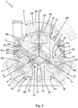
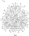
- the guide jackets 23 (and hence also the guide seats 3 at which the heads 4 are mounted with their membranes 6 moved by the respective pistons 8) are angularly distributed equidistant from each other, in particular at an angular distance of 120° each from the adjacent one, as illustrated in the enclosed figures 4 and 5 .
- each guide jacket 23 is advantageously provided with a lateral wall 24 placed to delimit the corresponding guide seat 3, so as to increase the precision with which the piston 8 translates between the release position and the compression position within the corresponding guide jacket 23.
- each piston 8 is slidably inserted substantially to size in the guide seat 3 delimited by the corresponding lateral wall 24.
- each guide jacket 23 has substantially circular extension around the radial direction X and the thrust body 54 of the piston 8 has substantially circular plan shape.
- the casing 2 also comprises a central support body 32 delimiting, at least laterally around the rotation axis Y, the containment chamber 38 and provided with at least three lateral openings 33, one for each head 4, which are extended starting from the containment chamber 38 and are each aligned with the radial direction X of a corresponding guide seat 3.
- the central support body 32 of the casing 2 has substantially prismatic shape, is extended along a main extension axis Z between two opposite terminal faces 36, is provided with one or more lateral faces 37, one for each head 4, substantially planar (preferably parallel to the main extension axis Z and perpendicular to the terminal faces 36), and on each of which a corresponding lateral opening 33 is made.
- the rotation axis Y of the drive shaft 9 preferably coincides with the main extension axis Z of the central support body 32 of the casing 2.
- At least the central support body 32 is made of aluminum or or an alloy thereof, in order to make the casing 2 as light as possible, as this is one of the heaviest components of of the present reciprocating pump 1.
- each guide jacket 23 comprises a positioning flange 27 extended transversely starting from the lateral wall 24 and retained at least between the corresponding head 4 and the central support body 32 of the casing 2.
- the lateral wall 24 of the guide jacket 23 is extended along the radial direction X at least partially within the corresponding lateral opening 33, in a manner such that the guide seats 3 are in turn extended inside the central support body 32 of the casing 2, thus reducing the overall bulk of the present reciprocating pump 1.
- each head 3 is preferably retained between the corresponding head 4 and the central support body 32 of the casing 2.
- each lateral opening 33 is provided with an enlarged portion 60 at the respective lateral face 37, in order to at least partially house the positioning flange 27 of the corresponding guide jacket 23.
- each lateral opening 33 defines, on the central support body 32, corresponding abutment steps 47 against which the positioning flanges 27 are placed in abutment.
- the positioning flanges 27 are completely housed in the enlarged portion 60 of the corresponding lateral openings 33 and placed in abutment against the respective abutment step 47, and the membranes 6 are pressed with pressure against the positioning flanges 27 by the corresponding heads 4 mounted on the casing 2.
- the positioning flanges 27 and the enlarged portions 60 of the lateral openings 33 have shape that is substantially counter-shaped with respect to each other.
- each head 4 advantageously comprises a shaped body 48 provided with a rear face 49, directed in opposite sense with respect to the central support body 32 and hence intended to remain visible, and with a front face 50, which, like the lateral faces 37 of the central support body 32, has substantially planar extension, so as to be mechanically coupled to one of these.
- multiple through holes are preferably made on the shaped body 48 of the head 4, and on each lateral face 37 of the central support body 32, multiple threaded holes are made corresponding to the through holes of the heads 4, in order to attain a bolted connection between each head 4 and the central support body 32.
- the pumping chamber 5 of each head 4 is made by means of a substantially cap-shaped concavity on the front face 50 and is closed by a corresponding membrane 6, which is advantageously retained between the head 4 itself and the central support body 32 of the casing 2, in particular between the front face 50 of the head 4 and the positioning flange 27 of the corresponding guide jacket 23 in abutment against the respective abutment step 47, as described above.
- a centering seat 51 is advantageously made, around the concavity that at least partially defines the pumping chamber 5, and such centering seat 51 at least partially houses the membrane 6, which is in turn preferably at least partially housed in the enlarged portion 60 of the corresponding lateral opening 33.
- each guide jacket 23 might not be inserted within a corresponding lateral opening 33, but rather it can be projectingly extended with respect to the corresponding lateral face 37 of the central support body 32, always aligned with the lateral opening 33.
- each guide jacket 23 advantageously comprises a first fixing flange, which is extended radially starting from a first terminal end of the lateral wall 24 and is mechanically coupled to the corresponding lateral face 37 of the central support body 32, e.g.
- the actuation means 7 also comprise one or more rocker arms 11, each of which rotatably connected to the casing 2 by means of a pin 12 and provided with a first lever arm 13 acting on a corresponding piston 8, and a second lever arm 14 opposite the first lever arm 13 with respect to the pin 12, and at least one return cam 15, which is fixed on the drive shaft 9 and is actuatable to rotate around the rotation axis Y in order to move each rocker arm 11 around the corresponding pin 12.
- Each rocker arm 11 is movable between an operative position, in which the return cam 15 acts against the second lever arm 14 in order to return, by means of the corresponding first lever arm 13, the corresponding piston 8 to slide from the compression position towards the release position, and a non-operative position, in which the return cam 15 releases the second lever arm 14 in order to free the corresponding piston 8 to slide from the release position towards the compression position.
- each rocker arm 11 is provided with an enlarged central portion 77 interposed between first lever arm 13 and second lever arm 14.
- each rocker arm 11 is movable around the corresponding pin 12 in a first rotation direction from the non-operative position to the operative position, in which the return cam 15 acts against the second lever arm 14 in order to push, by means of the corresponding first lever arm 13, the corresponding piston 8 to slide along the respective radial direction X with a return travel from the compression position towards the release position.
- each rocker arm 11 is preferably movable in a second rotation direction, opposite the first, from the operative position to the non-operative position, in which the return cam 15 releases the second lever arm 14 in order to free the corresponding piston 8 to slide along the respective radial direction X with a delivery travel from the release position towards the compression position.
- each piston 8 actuates in the corresponding guide seat 3 along the radial direction X with a delivery travel from the release position to the compression position and the return cam 15 actuates, by means of the rocker arms 11, each piston 8 to translate with a return travel from the compression position to the release position. More in detail, as is better described hereinbelow, providing for two separate cams - i.e.
- the thrust cam 10 arranged for acting directly on the pistons 8, pushing them from the release position to the compression position and the return cam 15 arranged for acting on the pistons 8 through the corresponding rocker arms 11, returning them from the compression position to the release position - allows imparting to the pistons 8 different speeds and accelerations in their motion from the release position to the compression position and in their motion from the compression position to the release position, and such different speeds and accelerations are preferably sized as a function of the different operative parameters of the pump, such as for example the characteristics of the fluid that must be pumped, the pressure of the plant in which the pump is intended to be installed downstream or upstream of the pump itself, the loads and the stresses that are developed during the suction of the liquid into the pumping chamber 5 and during the dispensing of the aforesaid liquid to be pumped and the like.
- the thrust cam 10 is shaped in a manner such to impart, during the rotation of the drive shaft 9, a first motion law (i.e. a first speed law and a first acceleration law) to the pistons 8 and, in addition, the return cam 15 is shaped in a manner such to impart, through the rocker arms 11, during the rotation of the drive shaft 9, a second motion law (i.e. a second speed law and a second acceleration law) to the pistons 8 which is different than the aforesaid first motion law.
- a first motion law i.e. a first speed law and a first acceleration law
- the return cam 15 is shaped in a manner such to impart, through the rocker arms 11, during the rotation of the drive shaft 9, a second motion law (i.e. a second speed law and a second acceleration law) to the pistons 8 which is different than the aforesaid first motion law.
- the thrust cam 10 is provided with a first lateral abutment surface arranged for receiving the pistons 8 in abutment, and more particularly their corresponding cam followers 19, and the return cam 15 is provided with a second lateral abutment surface for receiving in abutment the second lever arms 14 of the rocker arms 11.
- the first lateral abutment surface of the thrust cam 10 is provided with at least one thrust point, which is placed at a first radial distance from the rotation axis Y and determines the compression position of the pistons 8 and the second lateral abutment surface of the return cam 15 is provided with at least one release point, which is placed at a second radial distance from the rotation axis Y and determines the non-operative position of the rocker arms 11.
- the thrust point of the thrust cam 10 and the release point of the return cam 15 are angularly spaced around the rotation axis Y in a manner such that, with the thrust point placed at a piston 8, the release point is placed at the second lever arm 14 of the rocker arm 11 corresponding to the aforesaid piston 8.
- the second lateral abutment surface of the return cam 15 is provided with at least one return point, which is placed at a third radial distance from the rotation axis Y greater than the second radial distance and determines the operative position of the rocker arms 11, and the first lateral abutment surface of the thrust cam 10 is provided with at least one release point, which is placed at a fourth radial distance lower than the first radial distance and determines the release position of the pistons 8.
- the return point of the return cam 15 and the release point of the thrust cam 10 are equally spaced around the rotation axis Y such that, with the return point placed at the second thrust arm 14 of a rocker arm 11, the release point is placed at the piston 8 corresponding to the aforesaid rocker arm 11.
- the first lateral abutment surface of the thrust cam 10 is advantageously provided, with reference to the rotation direction of the same thrust cam 10 around the rotation axis Y, with a thrust section, which is extended from the release point to the thrust point, and with a release section, which is extended from the thrust point to the release point.
- the thrust profile and the release profile can have angular shape and/or size with respect to the rotation axis Y that are different from each other.
- the second lateral abutment surface of the return cam 15 is advantageously provided, with reference to the rotation direction of the same return cam 15 around the rotation axis Y, with a return profile, which is extended from the release point to the return point, and with a release profile, which is extended from the return point to the release point.
- the return profile and the release profile can have angular shape and/or size with respect to the rotation axis Y that are different from each other.
- the thrust cam 10 and the return cam 15 are attained in a single body and are fit on the drive shaft 9.
- thrust cam 10 and the return cam 15 can be made separately and both be fit on the drive shaft 9, preferably adjacent to each other.
- the thrust cam 10 and the return cam 15 can be made in a single body with the same drive shaft 9.
- each piston 8 comprises at least one abutment portion 16 extended substantially transverse to the radial direction X of the corresponding guide seat 3 and provided with a retention face 17 directed in the opposite direction with respect to the return cam 15, and preferably parallel to the rotation axis Y of the drive shaft 9.
- the first lever arm 14 of each rocker arm 11 is placed in abutment against the retention face 17 of the abutment portion 16 of the corresponding piston 8 both with the corresponding piston 8 sliding from the compression position towards the release position and with the corresponding piston 8 sliding from the release position towards the compression position (i.e. in particular both in the return travel and in the delivery travel).
- each piston 8 is laterally extended starting from the corresponding tappet element 18.
- the first lever arm 13 of each rocker arm 11 carries, mounted thereon, a corresponding rotary bearing, arranged for rotating in contact with the retention face 17 of the abutment portion 16, so as to reduce the friction between the first lever arm 13 and the retention face 17 and hence limit the wear thereof.
- each tappet element 18 i.e. in particular on its rear portion 67, a connection seat can be made and the first lever arm 13 of each rocker arm 11 is inserted in the connection seat of the corresponding tappet element 18.
- first lever arm 13 and the second lever arm 14 of each rocker arm 11 preferably form an angle between them that is substantially comprised between 75° and 125° and, still more preferably comprised between 85° and 115°, e.g. equal to 90° (as illustrated for example in figures 4 and 5 ).
- the pin 12 of each rocker arm 11 is extended within the containment chamber 38 substantially parallel to the drive shaft 9.
- each rocker arm 11 is preferably actuatable to rotate around a direction substantially parallel to the rotation axis Y of the thrust cam 10 and of the return cam 15.
- the casing 2 advantageously comprises at least one first closure wall 20 and a second closure wall 21 of the containment chamber 38, which face each other and placed to delimit the containment chamber 38 on opposite sides along the rotation axis Y.
- each rocker arm 11 is extended between a first end 44 thereof mechanically connected to the first closure wall 20 and a second end 45 mechanically connected to the second closure wall 21.
- the first closure wall 20 comprises one or more threaded holes 69, one for each pin 12, and the first end 44 of each pin 12 is threaded, in a manner such that the pins 12 are coupled via screwing to the first closure wall 20 at the threaded holes 69.
- the second closure wall 21 preferably comprises one or more blind holes 70, one for each pin 12, and the second end 45 of each pin 12 is inserted substantially to size in a corresponding blind hole 70, in a manner such that the first and the second closure wall 20, 21 maintain the substantially aligned pins 12 parallel to the rotation axis Y, even under the loads exerted by the return cam 15 on the second lever arm 14 of the corresponding rocker arm 11.
- first and the second closure wall 20, 21 respectively comprise a first and a second cover 53, 53', which are coupled to the terminal faces 36 and are placed to close the aforesaid access openings 52.
- the first cover 53 is advantageously provided with a blind seat 58, in which a terminal portion of the same drive shaft 9 is inserted (rotatably around the rotation axis Y) and the second cover 53' is provided with a through opening 57 traversed by the drive shaft 9 of the actuation means 7.
- a corresponding access opening 52 is made and only one between the first and the second closure wall 20, 21 comprises a first or second cover 53, 53' placed to close the aforesaid access opening 52, while the other between the second and the first closure wall 21, 20 is made in a single body with the central support body 32 and thus itself defines one of the terminal faces 36 of the central support body 32.
- each pin 12 comprises at least one first section 61 and a second section 62, which has smaller diameter than the first section 61.
- the first section 61 and the second section 62 are advantageously connected by a positioning shoulder 63, substantially aligned at the return cam 10.
- each rocker arm 11 is rotatably mounted on the second section 62 of the corresponding pin 12 in abutment against the positioning shoulder 63.
- each pin 12 carries, mounted on its second section 62, a spacer element 71 interposed between rocker arm 11 and first or second closure wall 20, 21 in order to maintain the corresponding rocker arm 11 against the positioning shoulder 63.
- the spacer element 71 is preferably interposed between the corresponding rocker arm 11 and the second closure wall 21.
- the spacer element 71 is interposed between the corresponding rocker arm 11 and the first closure wall 20.
- the lateral wall 24 of each guide jacket 23 is advantageously provided with at least one longitudinal opening 25 extended parallel to the radial direction X of the corresponding guide seat 3 and the respective piston 8 comprises at least one projecting element 26 slidably inserted in the longitudinal opening 25.
- each projecting element 26 comprises at least one alignment screw 72 provided with a threaded connection stem 73, which is inserted in a corresponding threaded seat made on the thrust body 54 of the corresponding piston 8 and is extended transversely with respect to the radial direction X, and with a projecting head 74, which is extended laterally projecting with respect to the thrust body 54 of the corresponding piston 8 and is slidably inserted in the longitudinal opening 25 of the corresponding guide jacket 23.
- the threaded seat is extended through up to the housing seat for the tappet element 18 (in particular up to the enlarged portion of the housing seat for the rear portion 67 of the tappet element 18).
- the tappet element 18 (i.e. in particular its rear portion 67) is provided with an alignment hole substantially aligned with the threaded seat and the alignment screw 72 of the projecting element 26 comprises an alignment section 75, which is extended starting from the threaded connection stem 73 and is inserted in the alignment hole, so as to prevent the rotation of the tappet element 18 within the housing seat on the corresponding thrust body 54 around the radial direction X.
- the thrust body 54 of each piston 8 has substantially polygonal plan shape, e.g. rectangular, and the lateral wall 24 of the guide jacket 23 delimits a corresponding guide seat 3 substantially counter-shaped with respect to the thrust body 54, always in order to prevent the rotation of the piston 8 around the radial direction X.
- the casing 2 comprises centering elements 28 each connected to the central support body 32 and to the positioning flange 27 of a corresponding guide jacket 23 and configured for blocking the rotation of the aforesaid positioning flange 27, with respect to the central support body 32, around the radial direction X.
- each piston 8 around the radial direction X thereof is blocked by the projecting element 26 slidably inserted in the longitudinal opening 25 on the lateral wall 24 of the guide jacket 23 and since the rotation of each guide jacket 23 around the aforesaid radial direction X is blocked by a suitable centering element 28 connected to the central support body 32 of the casing 2 and to the corresponding positioning flange 27, it is possible to prevent the bearing 64 of each cam follower 19 from modifying its own tilt around the radial direction X with respect to the thrust cam 10.
- the centering element 28 advantageously comprises multiple retention pins extended projecting from the central support body 32 of the casing 2 and/or from the positioning flange 27 of the respective guide jackets 23 and inserted in corresponding seats made on the positioning flanges 27 and/or on the central support body 32.
- the central support body 32 of the casing 2, at each head 4, comprises at least one first centering hole 29 and the positioning flange 27 of each guide jacket 23 comprises at least one corresponding second centering hole 30.
- the centering element 28 comprises at least one pin 31 at least partially inserted in the first centering hole 29 of the central support body 32 and in the second centering hole 30 of the positioning flange 27.
- first centering holes 29 are advantageously made on the abutment steps 47 inside the lateral openings 33 of the central support body 32 of the casing 2.
- the invention thus conceived therefore attains the pre-established objects.
Landscapes
- Engineering & Computer Science (AREA)
- Mechanical Engineering (AREA)
- General Engineering & Computer Science (AREA)
- Reciprocating Pumps (AREA)
Applications Claiming Priority (1)
| Application Number | Priority Date | Filing Date | Title |
|---|---|---|---|
| IT202100020915 | 2021-08-03 |
Publications (2)
| Publication Number | Publication Date |
|---|---|
| EP4130471A1 true EP4130471A1 (fr) | 2023-02-08 |
| EP4130471B1 EP4130471B1 (fr) | 2024-04-10 |
Family
ID=78463748
Family Applications (1)
| Application Number | Title | Priority Date | Filing Date |
|---|---|---|---|
| EP22188558.5A Active EP4130471B1 (fr) | 2021-08-03 | 2022-08-03 | Pompe à piston alternatif |
Country Status (3)
| Country | Link |
|---|---|
| EP (1) | EP4130471B1 (fr) |
| PL (1) | PL4130471T3 (fr) |
| WO (1) | WO2023012688A1 (fr) |
Families Citing this family (2)
| Publication number | Priority date | Publication date | Assignee | Title |
|---|---|---|---|---|
| EP4623196A1 (fr) * | 2022-11-21 | 2025-10-01 | The Regents of the University of Michigan | Mécanisme desmodromique et pompe à fluide |
| CN120027046A (zh) * | 2024-06-09 | 2025-05-23 | 张顺航 | 无油空压机头及气囊式空压机 |
Citations (5)
| Publication number | Priority date | Publication date | Assignee | Title |
|---|---|---|---|---|
| GB1074879A (en) * | 1963-11-16 | 1967-07-05 | Marie G R P | Improvements in or relating to variable delivery liquid pumps |
| US3433172A (en) | 1966-02-04 | 1969-03-18 | Fiat Spa | Fuel injection pump |
| CA2020472A1 (fr) | 1989-08-08 | 1991-02-09 | Kenneth E. Lehrke | Pompe a piston sans impulsions |
| GB2424455A (en) | 2005-03-23 | 2006-09-27 | Shane Engines Ltd | A motion converter and piston assembly |
| US20170260975A1 (en) * | 2016-03-14 | 2017-09-14 | Honda Motor Co., Ltd. | Diaphragm type fuel pump for general purpose engine |
-
2022
- 2022-08-03 EP EP22188558.5A patent/EP4130471B1/fr active Active
- 2022-08-03 WO PCT/IB2022/057205 patent/WO2023012688A1/fr not_active Ceased
- 2022-08-03 PL PL22188558.5T patent/PL4130471T3/pl unknown
Patent Citations (5)
| Publication number | Priority date | Publication date | Assignee | Title |
|---|---|---|---|---|
| GB1074879A (en) * | 1963-11-16 | 1967-07-05 | Marie G R P | Improvements in or relating to variable delivery liquid pumps |
| US3433172A (en) | 1966-02-04 | 1969-03-18 | Fiat Spa | Fuel injection pump |
| CA2020472A1 (fr) | 1989-08-08 | 1991-02-09 | Kenneth E. Lehrke | Pompe a piston sans impulsions |
| GB2424455A (en) | 2005-03-23 | 2006-09-27 | Shane Engines Ltd | A motion converter and piston assembly |
| US20170260975A1 (en) * | 2016-03-14 | 2017-09-14 | Honda Motor Co., Ltd. | Diaphragm type fuel pump for general purpose engine |
Also Published As
| Publication number | Publication date |
|---|---|
| WO2023012688A1 (fr) | 2023-02-09 |
| PL4130471T3 (pl) | 2024-09-02 |
| EP4130471B1 (fr) | 2024-04-10 |
Similar Documents
| Publication | Publication Date | Title |
|---|---|---|
| EP4130471B1 (fr) | Pompe à piston alternatif | |
| EP0437261B1 (fr) | Pompe à refoulement multiples | |
| KR20040010547A (ko) | 정량주입시스템 | |
| KR960001485A (ko) | 스풀을구비한 양변위 펌프 | |
| US9702329B2 (en) | Pump and common rail fuel injection system | |
| FR2487444A1 (fr) | Systeme et appareil de pompage de liquides dans des proportions predeterminees | |
| US4241714A (en) | Solenoid valve controlled fuel injection pump | |
| US4505240A (en) | Fuel injection pump of the distributor type | |
| GB1204103A (en) | Improvements in or relating to reciprocating pump liquid dispensing devices | |
| US3331327A (en) | Fuel pump | |
| CN1865687B (zh) | 内燃机引擎燃料泵 | |
| US2052737A (en) | Fuel feed mechanism for internal combustion engines | |
| EP4102069B1 (fr) | Pompe à mouvement alternatif | |
| US4893697A (en) | Injection lubricator with pulse counter | |
| US4893738A (en) | Self-aligning positive displacement dispenser | |
| GB2059516A (en) | Two-component Metering Pumps | |
| EP0027717A1 (fr) | Pompe à piston à effet simple | |
| US7395815B2 (en) | Fuel injection pump | |
| US2482733A (en) | Fuel injection pump | |
| SU1709922A3 (ru) | Регулирующее устройство топливного насоса высокого давлени | |
| EP0416737A1 (fr) | Appareil d'injection de carburant | |
| JPH06330831A (ja) | 内燃機関用の燃料噴射ポンプ | |
| JP2000230463A (ja) | 燃料噴射ポンプの吐出弁構造 | |
| US2672817A (en) | Fuel injection pump for internal-combustion engines | |
| US3937199A (en) | Fuel injection pump |
Legal Events
| Date | Code | Title | Description |
|---|---|---|---|
| PUAI | Public reference made under article 153(3) epc to a published international application that has entered the european phase |
Free format text: ORIGINAL CODE: 0009012 |
|
| STAA | Information on the status of an ep patent application or granted ep patent |
Free format text: STATUS: THE APPLICATION HAS BEEN PUBLISHED |
|
| AK | Designated contracting states |
Kind code of ref document: A1 Designated state(s): AL AT BE BG CH CY CZ DE DK EE ES FI FR GB GR HR HU IE IS IT LI LT LU LV MC MK MT NL NO PL PT RO RS SE SI SK SM TR |
|
| P01 | Opt-out of the competence of the unified patent court (upc) registered |
Effective date: 20230321 |
|
| STAA | Information on the status of an ep patent application or granted ep patent |
Free format text: STATUS: REQUEST FOR EXAMINATION WAS MADE |
|
| 17P | Request for examination filed |
Effective date: 20230804 |
|
| RBV | Designated contracting states (corrected) |
Designated state(s): AL AT BE BG CH CY CZ DE DK EE ES FI FR GB GR HR HU IE IS IT LI LT LU LV MC MK MT NL NO PL PT RO RS SE SI SK SM TR |
|
| GRAP | Despatch of communication of intention to grant a patent |
Free format text: ORIGINAL CODE: EPIDOSNIGR1 |
|
| STAA | Information on the status of an ep patent application or granted ep patent |
Free format text: STATUS: GRANT OF PATENT IS INTENDED |
|
| INTG | Intention to grant announced |
Effective date: 20231107 |
|
| GRAS | Grant fee paid |
Free format text: ORIGINAL CODE: EPIDOSNIGR3 |
|
| GRAA | (expected) grant |
Free format text: ORIGINAL CODE: 0009210 |
|
| STAA | Information on the status of an ep patent application or granted ep patent |
Free format text: STATUS: THE PATENT HAS BEEN GRANTED |
|
| AK | Designated contracting states |
Kind code of ref document: B1 Designated state(s): AL AT BE BG CH CY CZ DE DK EE ES FI FR GB GR HR HU IE IS IT LI LT LU LV MC MK MT NL NO PL PT RO RS SE SI SK SM TR |
|
| RAP3 | Party data changed (applicant data changed or rights of an application transferred) |
Owner name: IDROMECCANICA BERTOLINI S.P.A. |
|
| REG | Reference to a national code |
Ref country code: GB Ref legal event code: FG4D |
|
| REG | Reference to a national code |
Ref country code: CH Ref legal event code: EP |
|
| REG | Reference to a national code |
Ref country code: DE Ref legal event code: R096 Ref document number: 602022002802 Country of ref document: DE |
|
| REG | Reference to a national code |
Ref country code: IE Ref legal event code: FG4D |
|
| REG | Reference to a national code |
Ref country code: LT Ref legal event code: MG9D |
|
| REG | Reference to a national code |
Ref country code: NL Ref legal event code: MP Effective date: 20240410 |
|
| REG | Reference to a national code |
Ref country code: AT Ref legal event code: MK05 Ref document number: 1675152 Country of ref document: AT Kind code of ref document: T Effective date: 20240410 |
|
| PG25 | Lapsed in a contracting state [announced via postgrant information from national office to epo] |
Ref country code: NL Free format text: LAPSE BECAUSE OF FAILURE TO SUBMIT A TRANSLATION OF THE DESCRIPTION OR TO PAY THE FEE WITHIN THE PRESCRIBED TIME-LIMIT Effective date: 20240410 |
|
| PG25 | Lapsed in a contracting state [announced via postgrant information from national office to epo] |
Ref country code: NL Free format text: LAPSE BECAUSE OF FAILURE TO SUBMIT A TRANSLATION OF THE DESCRIPTION OR TO PAY THE FEE WITHIN THE PRESCRIBED TIME-LIMIT Effective date: 20240410 |
|
| PG25 | Lapsed in a contracting state [announced via postgrant information from national office to epo] |
Ref country code: IS Free format text: LAPSE BECAUSE OF FAILURE TO SUBMIT A TRANSLATION OF THE DESCRIPTION OR TO PAY THE FEE WITHIN THE PRESCRIBED TIME-LIMIT Effective date: 20240810 |
|
| PG25 | Lapsed in a contracting state [announced via postgrant information from national office to epo] |
Ref country code: BG Free format text: LAPSE BECAUSE OF FAILURE TO SUBMIT A TRANSLATION OF THE DESCRIPTION OR TO PAY THE FEE WITHIN THE PRESCRIBED TIME-LIMIT Effective date: 20240410 |
|
| PG25 | Lapsed in a contracting state [announced via postgrant information from national office to epo] |
Ref country code: FI Free format text: LAPSE BECAUSE OF FAILURE TO SUBMIT A TRANSLATION OF THE DESCRIPTION OR TO PAY THE FEE WITHIN THE PRESCRIBED TIME-LIMIT Effective date: 20240410 Ref country code: HR Free format text: LAPSE BECAUSE OF FAILURE TO SUBMIT A TRANSLATION OF THE DESCRIPTION OR TO PAY THE FEE WITHIN THE PRESCRIBED TIME-LIMIT Effective date: 20240410 |
|
| PG25 | Lapsed in a contracting state [announced via postgrant information from national office to epo] |
Ref country code: GR Free format text: LAPSE BECAUSE OF FAILURE TO SUBMIT A TRANSLATION OF THE DESCRIPTION OR TO PAY THE FEE WITHIN THE PRESCRIBED TIME-LIMIT Effective date: 20240711 |
|
| PG25 | Lapsed in a contracting state [announced via postgrant information from national office to epo] |
Ref country code: PT Free format text: LAPSE BECAUSE OF FAILURE TO SUBMIT A TRANSLATION OF THE DESCRIPTION OR TO PAY THE FEE WITHIN THE PRESCRIBED TIME-LIMIT Effective date: 20240812 |
|
| PG25 | Lapsed in a contracting state [announced via postgrant information from national office to epo] |
Ref country code: ES Free format text: LAPSE BECAUSE OF FAILURE TO SUBMIT A TRANSLATION OF THE DESCRIPTION OR TO PAY THE FEE WITHIN THE PRESCRIBED TIME-LIMIT Effective date: 20240410 |
|
| PG25 | Lapsed in a contracting state [announced via postgrant information from national office to epo] |
Ref country code: AT Free format text: LAPSE BECAUSE OF FAILURE TO SUBMIT A TRANSLATION OF THE DESCRIPTION OR TO PAY THE FEE WITHIN THE PRESCRIBED TIME-LIMIT Effective date: 20240410 |
|
| PG25 | Lapsed in a contracting state [announced via postgrant information from national office to epo] |
Ref country code: LV Free format text: LAPSE BECAUSE OF FAILURE TO SUBMIT A TRANSLATION OF THE DESCRIPTION OR TO PAY THE FEE WITHIN THE PRESCRIBED TIME-LIMIT Effective date: 20240410 |
|
| PG25 | Lapsed in a contracting state [announced via postgrant information from national office to epo] |
Ref country code: PT Free format text: LAPSE BECAUSE OF FAILURE TO SUBMIT A TRANSLATION OF THE DESCRIPTION OR TO PAY THE FEE WITHIN THE PRESCRIBED TIME-LIMIT Effective date: 20240812 Ref country code: NO Free format text: LAPSE BECAUSE OF FAILURE TO SUBMIT A TRANSLATION OF THE DESCRIPTION OR TO PAY THE FEE WITHIN THE PRESCRIBED TIME-LIMIT Effective date: 20240710 Ref country code: LV Free format text: LAPSE BECAUSE OF FAILURE TO SUBMIT A TRANSLATION OF THE DESCRIPTION OR TO PAY THE FEE WITHIN THE PRESCRIBED TIME-LIMIT Effective date: 20240410 Ref country code: IS Free format text: LAPSE BECAUSE OF FAILURE TO SUBMIT A TRANSLATION OF THE DESCRIPTION OR TO PAY THE FEE WITHIN THE PRESCRIBED TIME-LIMIT Effective date: 20240810 Ref country code: HR Free format text: LAPSE BECAUSE OF FAILURE TO SUBMIT A TRANSLATION OF THE DESCRIPTION OR TO PAY THE FEE WITHIN THE PRESCRIBED TIME-LIMIT Effective date: 20240410 Ref country code: GR Free format text: LAPSE BECAUSE OF FAILURE TO SUBMIT A TRANSLATION OF THE DESCRIPTION OR TO PAY THE FEE WITHIN THE PRESCRIBED TIME-LIMIT Effective date: 20240711 Ref country code: FI Free format text: LAPSE BECAUSE OF FAILURE TO SUBMIT A TRANSLATION OF THE DESCRIPTION OR TO PAY THE FEE WITHIN THE PRESCRIBED TIME-LIMIT Effective date: 20240410 Ref country code: ES Free format text: LAPSE BECAUSE OF FAILURE TO SUBMIT A TRANSLATION OF THE DESCRIPTION OR TO PAY THE FEE WITHIN THE PRESCRIBED TIME-LIMIT Effective date: 20240410 Ref country code: BG Free format text: LAPSE BECAUSE OF FAILURE TO SUBMIT A TRANSLATION OF THE DESCRIPTION OR TO PAY THE FEE WITHIN THE PRESCRIBED TIME-LIMIT Effective date: 20240410 Ref country code: AT Free format text: LAPSE BECAUSE OF FAILURE TO SUBMIT A TRANSLATION OF THE DESCRIPTION OR TO PAY THE FEE WITHIN THE PRESCRIBED TIME-LIMIT Effective date: 20240410 Ref country code: RS Free format text: LAPSE BECAUSE OF FAILURE TO SUBMIT A TRANSLATION OF THE DESCRIPTION OR TO PAY THE FEE WITHIN THE PRESCRIBED TIME-LIMIT Effective date: 20240710 |
|
| REG | Reference to a national code |
Ref country code: DE Ref legal event code: R097 Ref document number: 602022002802 Country of ref document: DE |
|
| PG25 | Lapsed in a contracting state [announced via postgrant information from national office to epo] |
Ref country code: DK Free format text: LAPSE BECAUSE OF FAILURE TO SUBMIT A TRANSLATION OF THE DESCRIPTION OR TO PAY THE FEE WITHIN THE PRESCRIBED TIME-LIMIT Effective date: 20240410 |
|
| PG25 | Lapsed in a contracting state [announced via postgrant information from national office to epo] |
Ref country code: EE Free format text: LAPSE BECAUSE OF FAILURE TO SUBMIT A TRANSLATION OF THE DESCRIPTION OR TO PAY THE FEE WITHIN THE PRESCRIBED TIME-LIMIT Effective date: 20240410 |
|
| PG25 | Lapsed in a contracting state [announced via postgrant information from national office to epo] |
Ref country code: CZ Free format text: LAPSE BECAUSE OF FAILURE TO SUBMIT A TRANSLATION OF THE DESCRIPTION OR TO PAY THE FEE WITHIN THE PRESCRIBED TIME-LIMIT Effective date: 20240410 |
|
| PG25 | Lapsed in a contracting state [announced via postgrant information from national office to epo] |
Ref country code: SK Free format text: LAPSE BECAUSE OF FAILURE TO SUBMIT A TRANSLATION OF THE DESCRIPTION OR TO PAY THE FEE WITHIN THE PRESCRIBED TIME-LIMIT Effective date: 20240410 Ref country code: RO Free format text: LAPSE BECAUSE OF FAILURE TO SUBMIT A TRANSLATION OF THE DESCRIPTION OR TO PAY THE FEE WITHIN THE PRESCRIBED TIME-LIMIT Effective date: 20240410 |
|
| PG25 | Lapsed in a contracting state [announced via postgrant information from national office to epo] |
Ref country code: SM Free format text: LAPSE BECAUSE OF FAILURE TO SUBMIT A TRANSLATION OF THE DESCRIPTION OR TO PAY THE FEE WITHIN THE PRESCRIBED TIME-LIMIT Effective date: 20240410 |
|
| PG25 | Lapsed in a contracting state [announced via postgrant information from national office to epo] |
Ref country code: SM Free format text: LAPSE BECAUSE OF FAILURE TO SUBMIT A TRANSLATION OF THE DESCRIPTION OR TO PAY THE FEE WITHIN THE PRESCRIBED TIME-LIMIT Effective date: 20240410 Ref country code: SK Free format text: LAPSE BECAUSE OF FAILURE TO SUBMIT A TRANSLATION OF THE DESCRIPTION OR TO PAY THE FEE WITHIN THE PRESCRIBED TIME-LIMIT Effective date: 20240410 Ref country code: RO Free format text: LAPSE BECAUSE OF FAILURE TO SUBMIT A TRANSLATION OF THE DESCRIPTION OR TO PAY THE FEE WITHIN THE PRESCRIBED TIME-LIMIT Effective date: 20240410 Ref country code: EE Free format text: LAPSE BECAUSE OF FAILURE TO SUBMIT A TRANSLATION OF THE DESCRIPTION OR TO PAY THE FEE WITHIN THE PRESCRIBED TIME-LIMIT Effective date: 20240410 Ref country code: DK Free format text: LAPSE BECAUSE OF FAILURE TO SUBMIT A TRANSLATION OF THE DESCRIPTION OR TO PAY THE FEE WITHIN THE PRESCRIBED TIME-LIMIT Effective date: 20240410 Ref country code: CZ Free format text: LAPSE BECAUSE OF FAILURE TO SUBMIT A TRANSLATION OF THE DESCRIPTION OR TO PAY THE FEE WITHIN THE PRESCRIBED TIME-LIMIT Effective date: 20240410 |
|
| PLBE | No opposition filed within time limit |
Free format text: ORIGINAL CODE: 0009261 |
|
| STAA | Information on the status of an ep patent application or granted ep patent |
Free format text: STATUS: NO OPPOSITION FILED WITHIN TIME LIMIT |
|
| 26N | No opposition filed |
Effective date: 20250113 |
|
| PG25 | Lapsed in a contracting state [announced via postgrant information from national office to epo] |
Ref country code: LU Free format text: LAPSE BECAUSE OF NON-PAYMENT OF DUE FEES Effective date: 20240803 |
|
| PG25 | Lapsed in a contracting state [announced via postgrant information from national office to epo] |
Ref country code: SI Free format text: LAPSE BECAUSE OF FAILURE TO SUBMIT A TRANSLATION OF THE DESCRIPTION OR TO PAY THE FEE WITHIN THE PRESCRIBED TIME-LIMIT Effective date: 20240410 Ref country code: MC Free format text: LAPSE BECAUSE OF FAILURE TO SUBMIT A TRANSLATION OF THE DESCRIPTION OR TO PAY THE FEE WITHIN THE PRESCRIBED TIME-LIMIT Effective date: 20240410 |
|
| REG | Reference to a national code |
Ref country code: BE Ref legal event code: MM Effective date: 20240831 |
|
| PG25 | Lapsed in a contracting state [announced via postgrant information from national office to epo] |
Ref country code: BE Free format text: LAPSE BECAUSE OF NON-PAYMENT OF DUE FEES Effective date: 20240831 |
|
| PG25 | Lapsed in a contracting state [announced via postgrant information from national office to epo] |
Ref country code: IE Free format text: LAPSE BECAUSE OF NON-PAYMENT OF DUE FEES Effective date: 20240803 |
|
| PG25 | Lapsed in a contracting state [announced via postgrant information from national office to epo] |
Ref country code: SE Free format text: LAPSE BECAUSE OF FAILURE TO SUBMIT A TRANSLATION OF THE DESCRIPTION OR TO PAY THE FEE WITHIN THE PRESCRIBED TIME-LIMIT Effective date: 20240410 |
|
| PGFP | Annual fee paid to national office [announced via postgrant information from national office to epo] |
Ref country code: DE Payment date: 20250820 Year of fee payment: 4 |
|
| PGFP | Annual fee paid to national office [announced via postgrant information from national office to epo] |
Ref country code: PL Payment date: 20250729 Year of fee payment: 4 Ref country code: TR Payment date: 20250728 Year of fee payment: 4 Ref country code: IT Payment date: 20250901 Year of fee payment: 4 |
|
| PGFP | Annual fee paid to national office [announced via postgrant information from national office to epo] |
Ref country code: FR Payment date: 20250828 Year of fee payment: 4 |
|
| PG25 | Lapsed in a contracting state [announced via postgrant information from national office to epo] |
Ref country code: CY Free format text: LAPSE BECAUSE OF FAILURE TO SUBMIT A TRANSLATION OF THE DESCRIPTION OR TO PAY THE FEE WITHIN THE PRESCRIBED TIME-LIMIT; INVALID AB INITIO Effective date: 20220803 |
|
| PG25 | Lapsed in a contracting state [announced via postgrant information from national office to epo] |
Ref country code: HU Free format text: LAPSE BECAUSE OF FAILURE TO SUBMIT A TRANSLATION OF THE DESCRIPTION OR TO PAY THE FEE WITHIN THE PRESCRIBED TIME-LIMIT; INVALID AB INITIO Effective date: 20220803 |
|
| REG | Reference to a national code |
Ref country code: CH Ref legal event code: H13 Free format text: ST27 STATUS EVENT CODE: U-0-0-H10-H13 (AS PROVIDED BY THE NATIONAL OFFICE) Effective date: 20260324 |
|
| PG25 | Lapsed in a contracting state [announced via postgrant information from national office to epo] |
Ref country code: CH Free format text: LAPSE BECAUSE OF NON-PAYMENT OF DUE FEES Effective date: 20250831 |