EP4130480A1 - Pompe centrifuge - Google Patents
Pompe centrifuge Download PDFInfo
- Publication number
- EP4130480A1 EP4130480A1 EP22188732.6A EP22188732A EP4130480A1 EP 4130480 A1 EP4130480 A1 EP 4130480A1 EP 22188732 A EP22188732 A EP 22188732A EP 4130480 A1 EP4130480 A1 EP 4130480A1
- Authority
- EP
- European Patent Office
- Prior art keywords
- pump
- chamber
- impeller
- centrifugal pump
- pump shaft
- Prior art date
- Legal status (The legal status is an assumption and is not a legal conclusion. Google has not performed a legal analysis and makes no representation as to the accuracy of the status listed.)
- Granted
Links
Images

Classifications
-
- F—MECHANICAL ENGINEERING; LIGHTING; HEATING; WEAPONS; BLASTING
- F04—POSITIVE - DISPLACEMENT MACHINES FOR LIQUIDS; PUMPS FOR LIQUIDS OR ELASTIC FLUIDS
- F04D—NON-POSITIVE-DISPLACEMENT PUMPS
- F04D1/00—Radial-flow pumps, e.g. centrifugal pumps; Helico-centrifugal pumps
-
- F—MECHANICAL ENGINEERING; LIGHTING; HEATING; WEAPONS; BLASTING
- F04—POSITIVE - DISPLACEMENT MACHINES FOR LIQUIDS; PUMPS FOR LIQUIDS OR ELASTIC FLUIDS
- F04D—NON-POSITIVE-DISPLACEMENT PUMPS
- F04D29/00—Details, component parts, or accessories
- F04D29/04—Shafts or bearings, or assemblies thereof
- F04D29/042—Axially shiftable rotors
-
- F—MECHANICAL ENGINEERING; LIGHTING; HEATING; WEAPONS; BLASTING
- F04—POSITIVE - DISPLACEMENT MACHINES FOR LIQUIDS; PUMPS FOR LIQUIDS OR ELASTIC FLUIDS
- F04D—NON-POSITIVE-DISPLACEMENT PUMPS
- F04D13/00—Pumping installations or systems
- F04D13/02—Units comprising pumps and their driving means
-
- F—MECHANICAL ENGINEERING; LIGHTING; HEATING; WEAPONS; BLASTING
- F04—POSITIVE - DISPLACEMENT MACHINES FOR LIQUIDS; PUMPS FOR LIQUIDS OR ELASTIC FLUIDS
- F04D—NON-POSITIVE-DISPLACEMENT PUMPS
- F04D13/00—Pumping installations or systems
- F04D13/02—Units comprising pumps and their driving means
- F04D13/06—Units comprising pumps and their driving means the pump being electrically driven
- F04D13/0686—Mechanical details of the pump control unit
-
- F—MECHANICAL ENGINEERING; LIGHTING; HEATING; WEAPONS; BLASTING
- F04—POSITIVE - DISPLACEMENT MACHINES FOR LIQUIDS; PUMPS FOR LIQUIDS OR ELASTIC FLUIDS
- F04D—NON-POSITIVE-DISPLACEMENT PUMPS
- F04D15/00—Control, e.g. regulation, of pumps, pumping installations or systems
- F04D15/0005—Control, e.g. regulation, of pumps, pumping installations or systems by using valves
-
- F—MECHANICAL ENGINEERING; LIGHTING; HEATING; WEAPONS; BLASTING
- F04—POSITIVE - DISPLACEMENT MACHINES FOR LIQUIDS; PUMPS FOR LIQUIDS OR ELASTIC FLUIDS
- F04D—NON-POSITIVE-DISPLACEMENT PUMPS
- F04D15/00—Control, e.g. regulation, of pumps, pumping installations or systems
- F04D15/0005—Control, e.g. regulation, of pumps, pumping installations or systems by using valves
- F04D15/0016—Control, e.g. regulation, of pumps, pumping installations or systems by using valves mixing-reversing- or deviation valves
-
- F—MECHANICAL ENGINEERING; LIGHTING; HEATING; WEAPONS; BLASTING
- F04—POSITIVE - DISPLACEMENT MACHINES FOR LIQUIDS; PUMPS FOR LIQUIDS OR ELASTIC FLUIDS
- F04D—NON-POSITIVE-DISPLACEMENT PUMPS
- F04D15/00—Control, e.g. regulation, of pumps, pumping installations or systems
- F04D15/0005—Control, e.g. regulation, of pumps, pumping installations or systems by using valves
- F04D15/0022—Control, e.g. regulation, of pumps, pumping installations or systems by using valves throttling valves or valves varying the pump inlet opening or the outlet opening
-
- F—MECHANICAL ENGINEERING; LIGHTING; HEATING; WEAPONS; BLASTING
- F04—POSITIVE - DISPLACEMENT MACHINES FOR LIQUIDS; PUMPS FOR LIQUIDS OR ELASTIC FLUIDS
- F04D—NON-POSITIVE-DISPLACEMENT PUMPS
- F04D25/00—Pumping installations or systems
- F04D25/02—Units comprising pumps and their driving means
- F04D25/06—Units comprising pumps and their driving means the pump being electrically driven
-
- F—MECHANICAL ENGINEERING; LIGHTING; HEATING; WEAPONS; BLASTING
- F04—POSITIVE - DISPLACEMENT MACHINES FOR LIQUIDS; PUMPS FOR LIQUIDS OR ELASTIC FLUIDS
- F04D—NON-POSITIVE-DISPLACEMENT PUMPS
- F04D29/00—Details, component parts, or accessories
- F04D29/04—Shafts or bearings, or assemblies thereof
- F04D29/043—Shafts
-
- F—MECHANICAL ENGINEERING; LIGHTING; HEATING; WEAPONS; BLASTING
- F04—POSITIVE - DISPLACEMENT MACHINES FOR LIQUIDS; PUMPS FOR LIQUIDS OR ELASTIC FLUIDS
- F04D—NON-POSITIVE-DISPLACEMENT PUMPS
- F04D29/00—Details, component parts, or accessories
- F04D29/04—Shafts or bearings, or assemblies thereof
- F04D29/046—Bearings
-
- F—MECHANICAL ENGINEERING; LIGHTING; HEATING; WEAPONS; BLASTING
- F04—POSITIVE - DISPLACEMENT MACHINES FOR LIQUIDS; PUMPS FOR LIQUIDS OR ELASTIC FLUIDS
- F04D—NON-POSITIVE-DISPLACEMENT PUMPS
- F04D29/00—Details, component parts, or accessories
- F04D29/40—Casings; Connections of working fluid
- F04D29/42—Casings; Connections of working fluid for radial or helico-centrifugal pumps
-
- F—MECHANICAL ENGINEERING; LIGHTING; HEATING; WEAPONS; BLASTING
- F04—POSITIVE - DISPLACEMENT MACHINES FOR LIQUIDS; PUMPS FOR LIQUIDS OR ELASTIC FLUIDS
- F04D—NON-POSITIVE-DISPLACEMENT PUMPS
- F04D29/00—Details, component parts, or accessories
- F04D29/40—Casings; Connections of working fluid
- F04D29/42—Casings; Connections of working fluid for radial or helico-centrifugal pumps
- F04D29/426—Casings; Connections of working fluid for radial or helico-centrifugal pumps especially adapted for liquid pumps
-
- F—MECHANICAL ENGINEERING; LIGHTING; HEATING; WEAPONS; BLASTING
- F04—POSITIVE - DISPLACEMENT MACHINES FOR LIQUIDS; PUMPS FOR LIQUIDS OR ELASTIC FLUIDS
- F04D—NON-POSITIVE-DISPLACEMENT PUMPS
- F04D7/00—Pumps adapted for handling specific fluids, e.g. by selection of specific materials for pumps or pump parts
- F04D7/02—Pumps adapted for handling specific fluids, e.g. by selection of specific materials for pumps or pump parts of centrifugal type
- F04D7/04—Pumps adapted for handling specific fluids, e.g. by selection of specific materials for pumps or pump parts of centrifugal type the fluids being viscous or non-homogenous
Definitions
- This application relates to the field of mechanical engineering pump technologies, and in particular, to a centrifugal pump.
- a pump is a machine that conveys or pressurizes a fluid.
- the pump transfers mechanical energy of a prime mover or other external energy to liquid, to increase energy of the liquid.
- a pump that drives liquid through an impeller to rotate at high speed to transfer mechanical energy to a conveyed liquid is an impeller pump.
- the impeller pump includes a centrifugal pump. The centrifugal pump conveys liquid by a centrifugal force generated during rotation of an impeller.
- the centrifugal pump may include a pump casing, a motor, a pump shaft, and an impeller.
- the motor drives the pump shaft to rotate the impeller in a working chamber of the pump casing. Liquid may be discharged from the working chamber to a drainage pipe by a centrifugal force generated during rotation of the impeller.
- centrifugal pump In the centrifugal pump, a small fit clearance between the impeller and the working chamber corresponds to a high head and high performance efficiency. However, the impeller is easily stuck, resulting in poor reliability. To be specific, a head and reliability of the centrifugal pump are contradictory in mechanism. The centrifugal pump in the related technology can hardly meet requirements of high head and high reliability at the same time.
- An embodiment of this application provides a centrifugal pump, to meet requirements of high head and high reliability of a pump.
- this embodiment of this application provides a centrifugal pump.
- the centrifugal pump includes a pump casing and a first drive mechanism, a second drive mechanism, a pump shaft, and an impeller that are disposed in the pump casing.
- the pump casing includes a first chamber and a second chamber that are connected.
- An axis of the pump shaft coincides with axes of the first chamber and the second chamber.
- An inner diameter of the second chamber is greater than that of the first chamber.
- the impeller is connected to an end of the pump shaft.
- the first drive mechanism and the second drive mechanism are connected to the pump shaft and located on a side, away from the impeller, of the pump shaft.
- the first drive mechanism is configured to drive the pump shaft to rotate.
- the second drive mechanism is configured to drive the pump shaft to move along the axis.
- the impeller is driven by the pump shaft to rotate in the first chamber or the second chamber.
- Two chambers with different inner diameters are disposed in the pump casing of the centrifugal pump provided in this embodiment of this application, and drive mechanisms that drive the impeller to move in the two chambers are also disposed in the pump casing. Because of a small clearance between the impeller and an inner wall of the first chamber, the centrifugal pump can give play to characteristics of high flow and high head. After the impeller is stuck by large particle impurities, the drive mechanisms drive the impeller to the second chamber. Because of a large clearance between the impeller and an inner wall of the second chamber, the centrifugal pump has strong impurity resistance and the impeller may be released from a stuck state. High performance and high reliability of the centrifugal pump may be implemented by controlling switching of two operating modes.
- the first drive mechanism includes a first bearing, a motor, and a second bearing that are sequentially connected to the pump shaft.
- the motor is configured to drive the pump shaft to rotate.
- the first bearing and the second bearing are sleeved outside the pump shaft.
- the first bearing is located on the side, away from the impeller, of the pump shaft.
- the motor may drive the pump shaft to rotate.
- the first bearing and the second bearing are configured to support the rotating pump shaft, to reduce a friction coefficient during rotation of the pump shaft, so that rotation precision of the pump shaft is ensured.
- the first drive mechanism further includes a first slide and a second slide.
- the first slide and the second slide are fixed in the pump casing.
- the first bearing is connected in the first slide and may slide in a direction of the axis of the pump shaft in the first slide.
- the second bearing is connected in the second slide and may slide in the direction of the axis of the pump shaft in the second slide.
- the first slide is configured to ensure that the first bearing is fixed in the pump casing and moves axially.
- the second slide is configured to ensure that the second bearing is fixed in the pump casing and moves axially.
- the first slide and the second slide may cooperate with the sliding of the first bearing and the second bearing, to enable the pump shaft to move more smoothly, and the operating modes of the centrifugal pump to be switched more smoothly.
- the second drive mechanism includes a coil, a spring, and an armature.
- the armature is disposed on a side, facing away from the motor, of the first bearing.
- the armature is connected to the first bearing through the spring.
- a direction of contraction of the spring is parallel to or coincides with a direction of the axis of the pump shaft.
- the armature is connected to the coil.
- the coil may be energized to turn the armature into a magnetic attraction structure.
- the coil may form a magnetic field after being energized.
- the armature may form a magnetic attraction force and may attract the first bearing, and the spring 32 is compressed, so that the first bearing, the second bearing, the pump shaft, and the impeller move as a whole. Then, the impeller is switched to move in the first chamber or in the second chamber.
- the centrifugal pump further includes an ammeter and a tachometer.
- the second drive mechanism further includes a controller connected to the coil.
- the controller is connected to the ammeter or the tachometer.
- the controller is configured to receive a current signal from the ammeter or a rotational speed signal from the tachometer, and control the coil to be energized or de-energized based on the current signal or the rotational speed signal.
- the controller is configured to detect an abnormal current signal or an abnormal rotational speed signal, to control the coil to be energized and de-energized. Therefore, the impeller may be timely released from a stuck state, to improve performance and reliability of the centrifugal pump.
- the second drive mechanism further includes a manual switch.
- the manual switch is connected to the coil and is configured to control the coil to be energized or de-energized.
- the manual switch is configured to control the coil to be energized or de-energized, to facilitate a user to operate.
- the impeller may be released from the stuck state, to improve performance and reliability of the centrifugal pump.
- the second chamber is located on a side, facing away from the first drive mechanism, of the first chamber.
- the second chamber with a large inner diameter is located at the bottom of the pump casing, so that the centrifugal pump has an aesthetic appearance and a low overall center, and the centrifugal pump may be placed stably.
- the centrifugal pump further includes a first branch pipe and a second branch pipe.
- the first branch pipe is connected to a side wall of the first chamber
- the second branch pipe is connected to a side wall of the second chamber.
- the first branch pipe and the second branch pipe come together and are connected to a drainage pipe.
- the first branch pipe and the second branch pipe are disposed respectively on the side walls of the first chamber and the second chamber, so that liquid can be smoothly discharged in the two operating modes of the centrifugal pump. Therefore, the centrifugal pump has higher drainage efficiency than a centrifugal pump in which only one drainage pipe is disposed.
- a first one-way valve is disposed on the first branch pipe and a second one-way valve is disposed on the second branch pipe.
- a one-way valve is disposed on each of the first branch pipe and the second branch pipe, so that liquid is discharged only from the first branch pipe in an operating mode 1 or discharged only from the second branch pipe in an operating mode 2. In this way, liquid in one branch pipe is prevented from flowing back to the other branch pipe, to ensure a drainage effect.
- the centrifugal pump is a vertical pump, and the pump casing and the axis of the pump shaft are vertical with respect to a horizontal plane.
- the first chamber and the second chamber are filled with liquid, and the impeller is immersed in the liquid.
- the first bearing, the motor, and the second bearing may be disposed sequentially from top to bottom, located at an upper part of the pump casing and separated from a liquid surface.
- Two chambers with different inner diameters are disposed in the pump casing of the centrifugal pump provided in this embodiment of this application, and the drive mechanisms that drive the impeller to move in the two chambers are also disposed in the pump casing. Because of the small clearance between the impeller and the inner wall of the first chamber, the centrifugal pump can give play to the characteristics of high flow and high head. After the impeller is stuck by large particle impurities, the drive mechanisms drive the impeller to the second chamber. Because of the large clearance between the impeller and the inner wall of the second chamber, the centrifugal pump has strong impurity resistance and the impeller may be released from the stuck state. High performance and high reliability of the centrifugal pump may be implemented by controlling switching of the two operating modes. Further, the armature, the coil, and the spring are ingeniously used to form a magnetic drive mechanism, so that the impeller moves smoothly in a direction of the axis.
- 100- pump casing 100- working chamber; 11- first chamber; 12- second chamber; 13- first branch pipe; 131- first one-way valve; 14- second branch pipe; 141- second one-way valve; 15- drainage pipe; 200- first drive mechanism; 21- motor; 22- first bearing; 23- second bearing; 24- first slide; 25- second slide; 300- second drive mechanism; 31- coil; 32- spring; 33- armature; 400- pump shaft; and 500- impeller.
- a centrifugal pump conveys liquid by a centrifugal force generated during rotation of an impeller.
- the centrifugal pump may be used in a plurality of fields, such as a drainage process of a cooling system in a data center.
- the centrifugal pump may usually include a pump casing, a motor, a pump shaft, and an impeller.
- the motor drives the pump shaft to rotate the impeller in a working chamber of the pump casing.
- Liquid may be discharged from the working chamber to a drainage pipe by a centrifugal force generated during rotation of the impeller.
- the centrifugal pump has two important parameters, namely, performance and reliability.
- a head is a key characteristic of the performance of the centrifugal pump.
- the head refers to a height at which water can be pumped up by a water pump, and is an important working performance parameter of the pump.
- the head is also referred to as a pressure head, and may be expressed as an increase in a pressure energy head, a kinetic energy head and a potential energy head of a fluid.
- the head of the centrifugal pump includes two parts based on a centerline of the impeller, and is a sum of a suction head and a pressurized head.
- the suction head is a height at which a water pump can suck water, and indicates a vertical height from a centerline of an impeller of the water pump to a source water surface.
- the pressurized head is a height at which the pump can pressurize water, and indicates a vertical height from the centerline of the impeller of the water pump to a water surface of an outlet pond.
- Impurity resistance is a key characteristic of the reliability of the centrifugal pump.
- external impurities such as scale and gravel inevitably exist in water.
- the pump shaft or impeller may be stuck, resulting in a failure of the centrifugal pump. Therefore, the centrifugal pump has low reliability.
- the head and the impurity resistance of the centrifugal pump are closely related to a size of a clearance between mechanical parts in the centrifugal pump.
- the head and the reliability of the centrifugal pump are contradictory in mechanism.
- the centrifugal pump in a related technology can hardly meet requirements of high head and high reliability at the same time.
- FIG. 1 is a schematic diagram of a structure of a centrifugal pump provided in a related technology.
- the centrifugal pump may include a pump casing 100, a motor 21, a pump shaft 400, and an impeller 500.
- the motor 21, the pump shaft 400, and the impeller 500 are disposed in the pump casing 100.
- the motor 21 is connected to the pump shaft 400.
- the impeller 500 is connected to an end of the pump shaft 400.
- a working chamber 10 is disposed at the bottom of the pump casing 100, and a side wall of the working chamber 10 is connected to a drainage pipe 15.
- the impeller 500 is disposed in the working chamber 10. Driven by the motor 21, the pump shaft 400 drives the impeller 500 to rotate in the working chamber 10, to discharge liquid in the working chamber 10 from the drainage pipe 15.
- the centrifugal pump due to a small clearance between the impeller 500 and the working chamber 10, the centrifugal pump has high work efficiency. Further, the centrifugal pump has a high head under a same volume and power condition. Therefore, the centrifugal pump may meet a use requirement under a high performance condition. However, when the clearance L1' between the impeller 500 and the working chamber 10 is excessively small and if water contains impurities, the impeller is easily stuck during operation of the centrifugal pump, resulting in a fault in the centrifugal pump.
- FIG. 2 is a schematic diagram of another structure of a centrifugal pump provided in a related technology.
- the centrifugal pump may include a pump casing 100, a motor 21, a pump shaft 400, and an impeller 500.
- the centrifugal pump has the same components and component connection relationship as the centrifugal pump provided in FIG. 1 .
- a difference lies in that, in the another related technology, due to a large clearance L2' between the impeller 500 and the working chamber 10, it may be ensured that the impeller is not stuck by impurity particles, and related hard particle impurities are discharged from the pump along with water. Therefore, the centrifugal pump has high reliability.
- the impeller due to the large clearance, the impeller has low work efficiency and poor head performance. Therefore, performance of the centrifugal pump is degraded when the centrifugal pump has the same volume and power.
- the centrifugal pump when a fit clearance between the impeller and the working chamber is small, the centrifugal pump has a high head and high performance efficiency. However, impurity particles are easily stuck in the clearance, resulting in a failure and poor reliability of the centrifugal pump. Conversely, when the fit clearance between the impeller and the working chamber is large, the head of the centrifugal pump is reduced. However, impurity particles can be easily discharged, so that reliability of the pump is high. To be specific, performance and reliability of the centrifugal pump can hardly be compatible. The centrifugal pump in a related technology can meet only one requirement, and can hardly meet requirements of high head and high impurity resistance at the same time.
- two chambers with different inner diameters are disposed in the pump casing of the centrifugal pump provided in this embodiment of this application, and drive mechanisms that drive the impeller to move in the two chambers are also disposed in the pump casing. Because of a small clearance between the impeller and the inner wall of the first chamber, the centrifugal pump can give play to the characteristics of high flow and high head. After the impeller is stuck by large particle impurities, the drive mechanisms drive the impeller to the second chamber.
- the centrifugal pump has strong impurity resistance and the impeller returns to normal rotation. Therefore, high performance and high reliability of the centrifugal pump may be implemented.
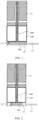
- FIG. 3 is a schematic diagram of a structure of a centrifugal pump provided in an embodiment of this application.
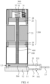
- FIG. 4 is a schematic diagram of a structure of the centrifugal pump in another state provided in this embodiment of this application.
- the centrifugal pump provided in this embodiment of this application may include a pump casing 100 and a first drive mechanism 200, a second drive mechanism 300, a pump shaft 400, and an impeller 500 that are disposed in the pump casing 100.
- the pump casing 100 may include a first chamber 11 and a second chamber 12 that are connected.
- An axis of the pump shaft 400 coincides with axes of the first chamber 11 and the second chamber 12.
- An inner diameter of the second chamber 12 is greater than that of the first chamber 11.
- the impeller 500 is connected to an end of the pump shaft 400. The impeller 500 may rotate in the first chamber 11 or the second chamber 12.
- the centrifugal pump provided in this embodiment of this application may have two operating modes.
- Operating mode 1 The impeller 500 is located in the first chamber 11, and because of a small clearance L1 between the impeller 500 and an inner wall of the first chamber 11, the centrifugal pump can give play to characteristics of high flow and high head.
- Operating mode 2 The impeller 500 is located in the second chamber 12, and because of a large clearance L2 between the impeller 500 and an inner wall of the second chamber, the centrifugal pump has strong impurity resistance and the impeller 500 is not easily stuck.
- the impeller 500 is controlled to move in the first chamber 11 or the second chamber 12 in different scenarios, so that high performance and high reliability of the centrifugal pump may be implemented.
- the first drive mechanism 200 is configured to reliably rotate the impeller 500.
- the first drive mechanism 200 is connected to the pump shaft 400, and is located on a side, away from the impeller 500, of the pump shaft 400.
- the first drive mechanism 200 is configured to drive the pump shaft 400 to rotate, so that the pump shaft 400 drives the impeller 500 to rotate.
- the first drive mechanism 200 may include a motor 21.
- the motor 21 is connected to the pump shaft 400 and may drive the pump shaft 400 to rotate.
- the first drive mechanism 200 may further include a first bearing 22 and a second bearing 23.
- the first bearing 22, the motor 21, and the second bearing 23, are sequentially connected to the pump shaft 400.
- the first bearing 22 and the second bearing 23 are sleeved outside the pump shaft 400.
- the first bearing 22 is located on the side, away from the impeller 500, of the pump shaft 400.
- the first bearing 22 and the second bearing 23 are configured to support the rotating pump shaft 400, to reduce a friction coefficient during rotation of the pump shaft 400, so that rotation precision of the pump shaft 400 is ensured.
- the centrifugal pump may be a vertical pump.
- the pump casing 100 and the axis of the pump shaft 400 are vertical with respect to a horizontal plane.
- the first chamber 11 and the second chamber 12 are located at the bottom of the pump casing 100.
- the centrifugal pump operates, the first chamber 11 and the second chamber 12 are filled with liquid, and the impeller 500 is immersed in the liquid.
- the first bearing 22, the motor 21, and the second bearing 23 may be disposed sequentially from top to bottom, located at an upper part of the pump casing 100, and separated from a liquid surface.
- the second drive mechanism 300 is configured to move the impeller 500 along the axis.
- the second drive mechanism 300 is connected to the pump shaft 400, and is located on the side, away from the impeller 500, of the pump shaft 400.
- the second drive mechanism 300 is configured to drive the pump shaft 400 to move along the axis, so that the impeller 500, when driven by the pump shaft 400, may be switched to move in the first chamber 11 or the second chamber 12.
- both the first bearing 22 and the second bearing 23 may be sliding bearings or rolling bearings.
- the first bearing 22, the second bearing 23, and the pump shaft 400 are connected into a whole, and the impeller 500 is fixedly connected to the end of the pump shaft 400, so that the first bearing 22, the second bearing 23, the pump shaft 400, and the impeller 500 are connected into a whole being mounted.
- a relative position of each component is fixed in space.
- the second drive mechanism 300 may drive the pump shaft 400 or the first bearing 22 to move, so that the impeller 500 is driven to move in a direction of the axis.
- the second drive mechanism 300 may include a coil 31, a spring 32, and an armature 33.
- the armature 33 is disposed on a side, facing away from the motor 21, of the first bearing 22, that is, the armature is disposed at the top of the pump casing 100.
- the armature 33 is connected to the first bearing 22 through the spring 32.
- a direction of contraction of the spring 32 is parallel to or coincides with a direction of the axis of the pump shaft 400.
- the armature 33 is connected to the coil 31, and the coil 31 may be energized to turn the armature 33 into a magnetic attraction structure.
- the coil 31 may form a magnetic field after being energized.
- the armature 33 may form a magnetic attraction force and may attract the first bearing 22 to compress the spring 32, so that the first bearing 22, the second bearing 23, the pump shaft 400, and the impeller 500 move as a whole, and then the impeller 500 is switched to move in the first chamber 11 or the second chamber 12.
- first chamber 11 and the second chamber 12 in the pump casing 100 are not specifically limited in this embodiment.
- the second chamber 12 may be located on a side, away from the first drive mechanism 200, of the first chamber 11.
- the second chamber 12 may be located below the first chamber 11.
- the armature 33 in an initial state in which the coil 31 is not energized, the armature 33 has no magnetic attraction force, and the spring 32 may be in an expanded state and press the first bearing 22, so that the impeller 500 may be located in the second chamber 12. After the coil 31 is energized, the armature 33 may attract the first bearing 22 to move upward, and the pump shaft 400 and the impeller 500 synchronously move upward, so that the impeller 500 is located in the first chamber 11.
- the first bearing 22 and the second bearing 23 each may have a circumferential fixing function. Further, the first bearing 22 may have a thrust function, so that the pump shaft 400 may have an axial positioning function.
- the first drive mechanism 200 further includes a first slide 24 and a second slide 25.
- the first slide 24 and the second slide 25 are fixed in the pump casing 100.
- the first bearing 22 is connected in the first slide 24 and may slide in a direction of the axis of the pump shaft 400 in the first slide 24.
- the second bearing 23 is connected in the second slide 25 and may slide in the direction of the axis of the pump shaft 400 in the second slide 25.
- the first slide 24 is configured to ensure that the first bearing 22 is fixed in the pump casing 100 and moves axially.
- the second slide 25 is configured to ensure that the second bearing 23 is fixed in the pump casing 100 and moves axially.
- the first slide 24 and the second slide 25 may cooperate with sliding of the first bearing 22 and the second bearing 23, to enable the pump shaft 400 to move more smoothly, and the operating modes of the centrifugal pump to be switched more smoothly.
- the coil 31 may be triggered to be energized or de-energized in different ways to implementing switching of the modes.
- a triggering mode is automatic triggering.
- the centrifugal pump further includes an ammeter and a tachometer.
- the second drive mechanism 300 may further include a controller connected to the coil 31.
- the controller is connected to the ammeter or the tachometer.
- the controller is configured to receive a current signal from the ammeter or a rotational speed signal from the tachometer, and control the coil 31 to be energized or de-energized based on the current signal or the rotational speed signal.
- the ammeter in the centrifugal pump is configured to detect an operating current of the pump when the pump operates. In a state in which the impeller 500 is stuck by large particle impurities, the current increases compared with that in a normal state.
- the tachometer in the centrifugal pump is configured to detect a rotational speed of the motor 21 or the pump shaft 400. The rotational speed decreases or changes to zero in a state in which the impeller 500 is stuck by large particle impurities.
- the controller may detect that a current signal or a rotational speed signal is normal. When the controller detects an increase in a current or a decrease in a rotational speed, it is determined that the impeller 500 may be stuck. Then, the controller may control the coil 31 to be de-energized. Under the action of the spring 32, the impeller 500 moves downward into the second chamber 12, and the centrifugal pump is switched to the operating mode 2. Because the clearance between the impeller 500 and an inner wall of the chamber is increased, the impeller 500 is released from a stuck state.
- the controller may control the coil 31 to be energized, and then the centrifugal pump returns to the operating mode 1 again, to ensure that the centrifugal pump gives play to the characteristics of high flow and high head.
- the controller is configured to detect an abnormal current signal or an abnormal rotational speed signal, to control the coil 31 to be energized or de-energized. Therefore, the impeller 500 may be timely released from a stuck state, to improve performance and reliability of the centrifugal pump.
- the triggering mode is manual triggering.
- the second drive mechanism 300 further includes a manual switch that is connected to the coil 31, and is configured to control the coil 31 to be energized or de-energized.
- the manual switch may be disposed outside the pump casing 100 of the centrifugal pump to facilitate manual operation by a user.
- the user When finding that the impeller 500 is stuck and the centrifugal pump operates abnormally, the user operates the manual switch to control the coil 31 to be de-energized, so that the centrifugal pump is switched from the operating mode 1 to the operating mode 2.
- the manual switch is operated again, and the coil 31 may be controlled to be energized, so that the centrifugal pump is switched from the operating mode 2 to the operating mode 1.
- An operating process of the centrifugal pump is as follows: To ensure performance of the centrifugal pump, the coil 31 is controlled to be in an energized state, so that the impeller 500 is located in the first chamber 11 and the centrifugal pump operates in the operating mode 1. When the impeller 500 is stuck, the coil 31 is manually or automatically triggered to be de-energized, so that the impeller 500 is located in the second chamber 12 and the centrifugal pump operates in the operating mode 2. After the centrifugal pump operates for a period of time, the coil 31 may be triggered to be energized again, so that the impeller 500 is located in the first chamber 11 and the centrifugal pump operates in the operating mode 1.
- the centrifugal pump further includes a first branch pipe 13 and a second branch pipe 14.
- the first branch pipe 13 is connected to a side wall of the first chamber 11.
- the second branch pipe 14 is connected to a side wall of the second chamber 12.
- the first branch pipe 13 and the second branch pipe 14 come together and are connected to the drainage pipe 15.
- liquid in the first chamber 11 may enter the first branch pipe 13 under the action of a centrifugal force and then is discharged through the drainage pipe 15.
- liquid in the second chamber 12 may enter the second branch pipe 14 under the action of a centrifugal force and then is discharged through the drainage pipe 15.
- the first branch pipe 13 and the second branch pipe 14 are disposed respectively on the side walls of the first chamber 11 and the second chamber 12, so that liquid can be smoothly discharged in the two operating modes. Therefore, the centrifugal pump has higher drainage efficiency than a centrifugal pump in which only one drainage pipe is disposed.
- a first one-way valve 131 may be disposed on the first branch pipe 13 and a second one-way valve 141 may be disposed on the second branch pipe 14. After the first one-way valve 131 is opened, liquid may flow only from the first chamber 11 to the drainage pipe 15. After the second one-way valve 141 is opened, liquid may flow only from the second chamber 12 to the drainage pipe 15.
- the first one-way valve 131 When the impeller 500 rotates in the first chamber 11, the first one-way valve 131 is opened and the second one-way valve 141 is closed. Therefore, the liquid in the first chamber 11 may enter the first branch pipe 13 under the action of a centrifugal force and then is discharged through the drainage pipe 15.
- the first one-way valve 131 When the impeller 500 rotates in the second chamber 12, the first one-way valve 131 is closed and the second one-way valve 141 is opened. Therefore, the liquid in the second chamber 12 may enter the second branch pipe 14 under the action of a centrifugal force and then is discharged through the drainage pipe 15.
- a one-way valve is disposed on each of the first branch pipe 13 and the second branch pipe 14, so that liquid is discharged only from the first branch pipe 13 in the operating mode 1 or discharged only from the second branch pipe 14 in the operating mode 2. In this way, liquid in one branch pipe is prevented from flowing back to the other branch pipe, to ensure a drainage effect.
- centrifugal pump In the centrifugal pump provided in this embodiment of this application, two chambers with different inner diameters are disposed in the pump casing, and drive mechanisms that drive the impeller to move in the two chambers are also disposed in the pump casing. Because of the small clearance between the impeller and an inner wall of the first chamber, the centrifugal pump can give play to the characteristics of high flow and high head. After the impeller is stuck by large particle impurities, the drive mechanisms drive the impeller to the second chamber. Because of the large clearance between the impeller and an inner wall of the second chamber, the centrifugal pump has strong impurity resistance and the impeller may be released from the stuck state. High performance and high reliability of the centrifugal pump may be implemented by controlling switching of two operating modes. Further, the armature, the coil, and the spring are ingeniously used to form a magnetic drive mechanism, so that the impeller moves smoothly in a direction of the axis.
Landscapes
- Engineering & Computer Science (AREA)
- Mechanical Engineering (AREA)
- General Engineering & Computer Science (AREA)
- Structures Of Non-Positive Displacement Pumps (AREA)
Applications Claiming Priority (1)
| Application Number | Priority Date | Filing Date | Title |
|---|---|---|---|
| CN202110900977.9A CN115704394A (zh) | 2021-08-06 | 2021-08-06 | 离心泵 |
Publications (2)
| Publication Number | Publication Date |
|---|---|
| EP4130480A1 true EP4130480A1 (fr) | 2023-02-08 |
| EP4130480B1 EP4130480B1 (fr) | 2024-08-21 |
Family
ID=82839105
Family Applications (1)
| Application Number | Title | Priority Date | Filing Date |
|---|---|---|---|
| EP22188732.6A Active EP4130480B1 (fr) | 2021-08-06 | 2022-08-04 | Pompe centrifuge |
Country Status (3)
| Country | Link |
|---|---|
| US (1) | US12038012B2 (fr) |
| EP (1) | EP4130480B1 (fr) |
| CN (1) | CN115704394A (fr) |
Citations (4)
| Publication number | Priority date | Publication date | Assignee | Title |
|---|---|---|---|---|
| US3162128A (en) * | 1961-06-14 | 1964-12-22 | Regulator A G | Combined distribution valve and pump |
| FR1563183A (fr) * | 1968-02-29 | 1969-04-11 | ||
| GB1379075A (en) * | 1973-01-16 | 1975-01-02 | Lanyon T B | Radial flow turbo-machines |
| US20010031202A1 (en) * | 2000-03-13 | 2001-10-18 | Ritz Pumpenfabrik Gmbh & Co., Kg | Rotatory pump having a knobbed impeller wheel, and a knobbed impeller wheel therefor |
Family Cites Families (6)
| Publication number | Priority date | Publication date | Assignee | Title |
|---|---|---|---|---|
| US3404631A (en) * | 1966-06-09 | 1968-10-08 | Westinghouse Electric Corp | Centrifugal pump |
| DE4020120A1 (de) * | 1990-06-25 | 1991-01-31 | Klaus Prof Dr Ing Affeld | Medizinische vorrichtung zur erzeugung eines alternierenden volumenstroms fuer den antrieb von implantierbaren blutpumpen |
| WO2000068032A1 (fr) * | 1999-05-06 | 2000-11-16 | J. Eberspächer Gmbh & Co. | Systeme de chauffage, notamment pour vehicules automobiles |
| JP4645210B2 (ja) * | 2005-02-03 | 2011-03-09 | トヨタ自動車株式会社 | ポンプ装置、冷却システムおよび燃料電池システム |
| US7789049B2 (en) * | 2008-07-14 | 2010-09-07 | Honda Motor Co., Ltd. | Variable capacity water pump via electromagnetic control |
| EP2753806B1 (fr) * | 2011-09-08 | 2015-11-11 | Pierburg Pump Technology GmbH | Pompe à liquide de refroidissement automobile commutable |
-
2021
- 2021-08-06 CN CN202110900977.9A patent/CN115704394A/zh active Pending
-
2022
- 2022-08-04 EP EP22188732.6A patent/EP4130480B1/fr active Active
- 2022-08-05 US US17/881,777 patent/US12038012B2/en active Active
Patent Citations (4)
| Publication number | Priority date | Publication date | Assignee | Title |
|---|---|---|---|---|
| US3162128A (en) * | 1961-06-14 | 1964-12-22 | Regulator A G | Combined distribution valve and pump |
| FR1563183A (fr) * | 1968-02-29 | 1969-04-11 | ||
| GB1379075A (en) * | 1973-01-16 | 1975-01-02 | Lanyon T B | Radial flow turbo-machines |
| US20010031202A1 (en) * | 2000-03-13 | 2001-10-18 | Ritz Pumpenfabrik Gmbh & Co., Kg | Rotatory pump having a knobbed impeller wheel, and a knobbed impeller wheel therefor |
Also Published As
| Publication number | Publication date |
|---|---|
| US20230049932A1 (en) | 2023-02-16 |
| CN115704394A (zh) | 2023-02-17 |
| EP4130480B1 (fr) | 2024-08-21 |
| US12038012B2 (en) | 2024-07-16 |
Similar Documents
| Publication | Publication Date | Title |
|---|---|---|
| US20200345909A1 (en) | Rotary Blood Pump | |
| CN106015032B (zh) | 离心压缩机 | |
| US11085450B2 (en) | Pump having a housing with internal and external planar surfaces defining a cavity with an axial flux motor driven impeller secured therein | |
| CN107630801A (zh) | 一种变量式鼠笼型机电液集成动力装置 | |
| EP4130480A1 (fr) | Pompe centrifuge | |
| CN1094569C (zh) | 潜水电动机泵 | |
| CN1987107A (zh) | 油冷式螺旋压缩机 | |
| CN113864211A (zh) | 磁悬浮泵、具有其的制冷设备和空调室外机 | |
| WO2014133397A1 (fr) | Ensemble turbomachine pourvu d'un dispositif de levage à arbre magnétique | |
| KR100661702B1 (ko) | 터보압축기 | |
| JP2017147783A (ja) | 回転機械の起動方法 | |
| CN111946621A (zh) | 变频压缩机供油机构 | |
| US4946353A (en) | External stator rolling rotor scroll compressor | |
| US20060013699A1 (en) | Hydraulic pump | |
| CN212454807U (zh) | 新型防抽空磁力驱动齿轮泵 | |
| JP2006009740A (ja) | 水中モータポンプ | |
| CN119492136A (zh) | 空调系统的控制方法 | |
| CN223794331U (zh) | 一种自平衡重载型不锈钢磁力泵 | |
| CN223305998U (zh) | 一种用于大型离心压缩机的蓄能供油系统 | |
| CN119304715B (zh) | 石英件全自动研磨装置 | |
| CN117748836B (zh) | 一种水泵用驱动电机 | |
| CN115276305B (zh) | 一种防惯性偏移的空心轴电机及其工作方法 | |
| CN217602946U (zh) | 一种高速离心泵机组 | |
| JP2017172770A (ja) | 回転機械の停止方法及び回転機械の制御装置 | |
| CN201202682Y (zh) | 双驱动对称平衡离心式卧泵 |
Legal Events
| Date | Code | Title | Description |
|---|---|---|---|
| PUAI | Public reference made under article 153(3) epc to a published international application that has entered the european phase |
Free format text: ORIGINAL CODE: 0009012 |
|
| STAA | Information on the status of an ep patent application or granted ep patent |
Free format text: STATUS: THE APPLICATION HAS BEEN PUBLISHED |
|
| AK | Designated contracting states |
Kind code of ref document: A1 Designated state(s): AL AT BE BG CH CY CZ DE DK EE ES FI FR GB GR HR HU IE IS IT LI LT LU LV MC MK MT NL NO PL PT RO RS SE SI SK SM TR |
|
| STAA | Information on the status of an ep patent application or granted ep patent |
Free format text: STATUS: REQUEST FOR EXAMINATION WAS MADE |
|
| 17P | Request for examination filed |
Effective date: 20230524 |
|
| RBV | Designated contracting states (corrected) |
Designated state(s): AL AT BE BG CH CY CZ DE DK EE ES FI FR GB GR HR HU IE IS IT LI LT LU LV MC MK MT NL NO PL PT RO RS SE SI SK SM TR |
|
| STAA | Information on the status of an ep patent application or granted ep patent |
Free format text: STATUS: EXAMINATION IS IN PROGRESS |
|
| 17Q | First examination report despatched |
Effective date: 20230908 |
|
| GRAP | Despatch of communication of intention to grant a patent |
Free format text: ORIGINAL CODE: EPIDOSNIGR1 |
|
| STAA | Information on the status of an ep patent application or granted ep patent |
Free format text: STATUS: GRANT OF PATENT IS INTENDED |
|
| INTG | Intention to grant announced |
Effective date: 20240412 |
|
| GRAS | Grant fee paid |
Free format text: ORIGINAL CODE: EPIDOSNIGR3 |
|
| GRAA | (expected) grant |
Free format text: ORIGINAL CODE: 0009210 |
|
| STAA | Information on the status of an ep patent application or granted ep patent |
Free format text: STATUS: THE PATENT HAS BEEN GRANTED |
|
| P01 | Opt-out of the competence of the unified patent court (upc) registered |
Free format text: CASE NUMBER: APP_37040/2024 Effective date: 20240620 |
|
| AK | Designated contracting states |
Kind code of ref document: B1 Designated state(s): AL AT BE BG CH CY CZ DE DK EE ES FI FR GB GR HR HU IE IS IT LI LT LU LV MC MK MT NL NO PL PT RO RS SE SI SK SM TR |
|
| REG | Reference to a national code |
Ref country code: GB Ref legal event code: FG4D |
|
| REG | Reference to a national code |
Ref country code: CH Ref legal event code: EP |
|
| REG | Reference to a national code |
Ref country code: DE Ref legal event code: R096 Ref document number: 602022005445 Country of ref document: DE |
|
| REG | Reference to a national code |
Ref country code: IE Ref legal event code: FG4D |
|
| REG | Reference to a national code |
Ref country code: LT Ref legal event code: MG9D |
|
| REG | Reference to a national code |
Ref country code: NL Ref legal event code: MP Effective date: 20240821 |
|
| PG25 | Lapsed in a contracting state [announced via postgrant information from national office to epo] |
Ref country code: NO Free format text: LAPSE BECAUSE OF FAILURE TO SUBMIT A TRANSLATION OF THE DESCRIPTION OR TO PAY THE FEE WITHIN THE PRESCRIBED TIME-LIMIT Effective date: 20241121 |
|
| REG | Reference to a national code |
Ref country code: AT Ref legal event code: MK05 Ref document number: 1715710 Country of ref document: AT Kind code of ref document: T Effective date: 20240821 |
|
| PG25 | Lapsed in a contracting state [announced via postgrant information from national office to epo] |
Ref country code: NL Free format text: LAPSE BECAUSE OF FAILURE TO SUBMIT A TRANSLATION OF THE DESCRIPTION OR TO PAY THE FEE WITHIN THE PRESCRIBED TIME-LIMIT Effective date: 20240821 Ref country code: GR Free format text: LAPSE BECAUSE OF FAILURE TO SUBMIT A TRANSLATION OF THE DESCRIPTION OR TO PAY THE FEE WITHIN THE PRESCRIBED TIME-LIMIT Effective date: 20241122 Ref country code: FI Free format text: LAPSE BECAUSE OF FAILURE TO SUBMIT A TRANSLATION OF THE DESCRIPTION OR TO PAY THE FEE WITHIN THE PRESCRIBED TIME-LIMIT Effective date: 20240821 Ref country code: PL Free format text: LAPSE BECAUSE OF FAILURE TO SUBMIT A TRANSLATION OF THE DESCRIPTION OR TO PAY THE FEE WITHIN THE PRESCRIBED TIME-LIMIT Effective date: 20240821 Ref country code: PT Free format text: LAPSE BECAUSE OF FAILURE TO SUBMIT A TRANSLATION OF THE DESCRIPTION OR TO PAY THE FEE WITHIN THE PRESCRIBED TIME-LIMIT Effective date: 20241223 |
|
| PG25 | Lapsed in a contracting state [announced via postgrant information from national office to epo] |
Ref country code: BG Free format text: LAPSE BECAUSE OF FAILURE TO SUBMIT A TRANSLATION OF THE DESCRIPTION OR TO PAY THE FEE WITHIN THE PRESCRIBED TIME-LIMIT Effective date: 20240821 |
|
| PG25 | Lapsed in a contracting state [announced via postgrant information from national office to epo] |
Ref country code: LV Free format text: LAPSE BECAUSE OF FAILURE TO SUBMIT A TRANSLATION OF THE DESCRIPTION OR TO PAY THE FEE WITHIN THE PRESCRIBED TIME-LIMIT Effective date: 20240821 |
|
| PG25 | Lapsed in a contracting state [announced via postgrant information from national office to epo] |
Ref country code: IS Free format text: LAPSE BECAUSE OF FAILURE TO SUBMIT A TRANSLATION OF THE DESCRIPTION OR TO PAY THE FEE WITHIN THE PRESCRIBED TIME-LIMIT Effective date: 20241221 Ref country code: AT Free format text: LAPSE BECAUSE OF FAILURE TO SUBMIT A TRANSLATION OF THE DESCRIPTION OR TO PAY THE FEE WITHIN THE PRESCRIBED TIME-LIMIT Effective date: 20240821 |
|
| PG25 | Lapsed in a contracting state [announced via postgrant information from national office to epo] |
Ref country code: HR Free format text: LAPSE BECAUSE OF FAILURE TO SUBMIT A TRANSLATION OF THE DESCRIPTION OR TO PAY THE FEE WITHIN THE PRESCRIBED TIME-LIMIT Effective date: 20240821 |
|
| PG25 | Lapsed in a contracting state [announced via postgrant information from national office to epo] |
Ref country code: RS Free format text: LAPSE BECAUSE OF FAILURE TO SUBMIT A TRANSLATION OF THE DESCRIPTION OR TO PAY THE FEE WITHIN THE PRESCRIBED TIME-LIMIT Effective date: 20241121 Ref country code: ES Free format text: LAPSE BECAUSE OF FAILURE TO SUBMIT A TRANSLATION OF THE DESCRIPTION OR TO PAY THE FEE WITHIN THE PRESCRIBED TIME-LIMIT Effective date: 20240821 |
|
| PG25 | Lapsed in a contracting state [announced via postgrant information from national office to epo] |
Ref country code: RS Free format text: LAPSE BECAUSE OF FAILURE TO SUBMIT A TRANSLATION OF THE DESCRIPTION OR TO PAY THE FEE WITHIN THE PRESCRIBED TIME-LIMIT Effective date: 20241121 Ref country code: PT Free format text: LAPSE BECAUSE OF FAILURE TO SUBMIT A TRANSLATION OF THE DESCRIPTION OR TO PAY THE FEE WITHIN THE PRESCRIBED TIME-LIMIT Effective date: 20241223 Ref country code: PL Free format text: LAPSE BECAUSE OF FAILURE TO SUBMIT A TRANSLATION OF THE DESCRIPTION OR TO PAY THE FEE WITHIN THE PRESCRIBED TIME-LIMIT Effective date: 20240821 Ref country code: NO Free format text: LAPSE BECAUSE OF FAILURE TO SUBMIT A TRANSLATION OF THE DESCRIPTION OR TO PAY THE FEE WITHIN THE PRESCRIBED TIME-LIMIT Effective date: 20241121 Ref country code: NL Free format text: LAPSE BECAUSE OF FAILURE TO SUBMIT A TRANSLATION OF THE DESCRIPTION OR TO PAY THE FEE WITHIN THE PRESCRIBED TIME-LIMIT Effective date: 20240821 Ref country code: LV Free format text: LAPSE BECAUSE OF FAILURE TO SUBMIT A TRANSLATION OF THE DESCRIPTION OR TO PAY THE FEE WITHIN THE PRESCRIBED TIME-LIMIT Effective date: 20240821 Ref country code: IS Free format text: LAPSE BECAUSE OF FAILURE TO SUBMIT A TRANSLATION OF THE DESCRIPTION OR TO PAY THE FEE WITHIN THE PRESCRIBED TIME-LIMIT Effective date: 20241221 Ref country code: HR Free format text: LAPSE BECAUSE OF FAILURE TO SUBMIT A TRANSLATION OF THE DESCRIPTION OR TO PAY THE FEE WITHIN THE PRESCRIBED TIME-LIMIT Effective date: 20240821 Ref country code: GR Free format text: LAPSE BECAUSE OF FAILURE TO SUBMIT A TRANSLATION OF THE DESCRIPTION OR TO PAY THE FEE WITHIN THE PRESCRIBED TIME-LIMIT Effective date: 20241122 Ref country code: FI Free format text: LAPSE BECAUSE OF FAILURE TO SUBMIT A TRANSLATION OF THE DESCRIPTION OR TO PAY THE FEE WITHIN THE PRESCRIBED TIME-LIMIT Effective date: 20240821 Ref country code: ES Free format text: LAPSE BECAUSE OF FAILURE TO SUBMIT A TRANSLATION OF THE DESCRIPTION OR TO PAY THE FEE WITHIN THE PRESCRIBED TIME-LIMIT Effective date: 20240821 Ref country code: BG Free format text: LAPSE BECAUSE OF FAILURE TO SUBMIT A TRANSLATION OF THE DESCRIPTION OR TO PAY THE FEE WITHIN THE PRESCRIBED TIME-LIMIT Effective date: 20240821 Ref country code: AT Free format text: LAPSE BECAUSE OF FAILURE TO SUBMIT A TRANSLATION OF THE DESCRIPTION OR TO PAY THE FEE WITHIN THE PRESCRIBED TIME-LIMIT Effective date: 20240821 |
|
| PG25 | Lapsed in a contracting state [announced via postgrant information from national office to epo] |
Ref country code: SM Free format text: LAPSE BECAUSE OF FAILURE TO SUBMIT A TRANSLATION OF THE DESCRIPTION OR TO PAY THE FEE WITHIN THE PRESCRIBED TIME-LIMIT Effective date: 20240821 Ref country code: DK Free format text: LAPSE BECAUSE OF FAILURE TO SUBMIT A TRANSLATION OF THE DESCRIPTION OR TO PAY THE FEE WITHIN THE PRESCRIBED TIME-LIMIT Effective date: 20240821 Ref country code: RO Free format text: LAPSE BECAUSE OF FAILURE TO SUBMIT A TRANSLATION OF THE DESCRIPTION OR TO PAY THE FEE WITHIN THE PRESCRIBED TIME-LIMIT Effective date: 20240821 |
|
| PG25 | Lapsed in a contracting state [announced via postgrant information from national office to epo] |
Ref country code: EE Free format text: LAPSE BECAUSE OF FAILURE TO SUBMIT A TRANSLATION OF THE DESCRIPTION OR TO PAY THE FEE WITHIN THE PRESCRIBED TIME-LIMIT Effective date: 20240821 |
|
| PG25 | Lapsed in a contracting state [announced via postgrant information from national office to epo] |
Ref country code: CZ Free format text: LAPSE BECAUSE OF FAILURE TO SUBMIT A TRANSLATION OF THE DESCRIPTION OR TO PAY THE FEE WITHIN THE PRESCRIBED TIME-LIMIT Effective date: 20240821 |
|
| PG25 | Lapsed in a contracting state [announced via postgrant information from national office to epo] |
Ref country code: IT Free format text: LAPSE BECAUSE OF FAILURE TO SUBMIT A TRANSLATION OF THE DESCRIPTION OR TO PAY THE FEE WITHIN THE PRESCRIBED TIME-LIMIT Effective date: 20240821 Ref country code: SK Free format text: LAPSE BECAUSE OF FAILURE TO SUBMIT A TRANSLATION OF THE DESCRIPTION OR TO PAY THE FEE WITHIN THE PRESCRIBED TIME-LIMIT Effective date: 20240821 |
|
| REG | Reference to a national code |
Ref country code: DE Ref legal event code: R097 Ref document number: 602022005445 Country of ref document: DE |
|
| PLBE | No opposition filed within time limit |
Free format text: ORIGINAL CODE: 0009261 |
|
| STAA | Information on the status of an ep patent application or granted ep patent |
Free format text: STATUS: NO OPPOSITION FILED WITHIN TIME LIMIT |
|
| 26N | No opposition filed |
Effective date: 20250522 |
|
| PG25 | Lapsed in a contracting state [announced via postgrant information from national office to epo] |
Ref country code: SE Free format text: LAPSE BECAUSE OF FAILURE TO SUBMIT A TRANSLATION OF THE DESCRIPTION OR TO PAY THE FEE WITHIN THE PRESCRIBED TIME-LIMIT Effective date: 20240821 |
|
| PGFP | Annual fee paid to national office [announced via postgrant information from national office to epo] |
Ref country code: DE Payment date: 20250702 Year of fee payment: 4 |
|
| REG | Reference to a national code |
Ref country code: CH Ref legal event code: H13 Free format text: ST27 STATUS EVENT CODE: U-0-0-H10-H13 (AS PROVIDED BY THE NATIONAL OFFICE) Effective date: 20260324 |
|
| PG25 | Lapsed in a contracting state [announced via postgrant information from national office to epo] |
Ref country code: MC Free format text: LAPSE BECAUSE OF FAILURE TO SUBMIT A TRANSLATION OF THE DESCRIPTION OR TO PAY THE FEE WITHIN THE PRESCRIBED TIME-LIMIT Effective date: 20240821 |
|
| PG25 | Lapsed in a contracting state [announced via postgrant information from national office to epo] |
Ref country code: LU Free format text: LAPSE BECAUSE OF NON-PAYMENT OF DUE FEES Effective date: 20250804 |
|
| PG25 | Lapsed in a contracting state [announced via postgrant information from national office to epo] |
Ref country code: CH Free format text: LAPSE BECAUSE OF NON-PAYMENT OF DUE FEES Effective date: 20250831 |