EP4130482A1 - Motorgebläsegruppe - Google Patents
Motorgebläsegruppe Download PDFInfo
- Publication number
- EP4130482A1 EP4130482A1 EP22188355.6A EP22188355A EP4130482A1 EP 4130482 A1 EP4130482 A1 EP 4130482A1 EP 22188355 A EP22188355 A EP 22188355A EP 4130482 A1 EP4130482 A1 EP 4130482A1
- Authority
- EP
- European Patent Office
- Prior art keywords
- wall
- hub
- motor
- connection
- keys
- Prior art date
- Legal status (The legal status is an assumption and is not a legal conclusion. Google has not performed a legal analysis and makes no representation as to the accuracy of the status listed.)
- Granted
Links
Images

Classifications
-
- F—MECHANICAL ENGINEERING; LIGHTING; HEATING; WEAPONS; BLASTING
- F04—POSITIVE - DISPLACEMENT MACHINES FOR LIQUIDS; PUMPS FOR LIQUIDS OR ELASTIC FLUIDS
- F04D—NON-POSITIVE-DISPLACEMENT PUMPS
- F04D29/00—Details, component parts, or accessories
- F04D29/26—Rotors specially for elastic fluids
- F04D29/28—Rotors specially for elastic fluids for centrifugal or helico-centrifugal pumps for radial-flow or helico-centrifugal pumps
- F04D29/281—Rotors specially for elastic fluids for centrifugal or helico-centrifugal pumps for radial-flow or helico-centrifugal pumps for fans or blowers
-
- F—MECHANICAL ENGINEERING; LIGHTING; HEATING; WEAPONS; BLASTING
- F04—POSITIVE - DISPLACEMENT MACHINES FOR LIQUIDS; PUMPS FOR LIQUIDS OR ELASTIC FLUIDS
- F04D—NON-POSITIVE-DISPLACEMENT PUMPS
- F04D25/00—Pumping installations or systems
- F04D25/02—Units comprising pumps and their driving means
- F04D25/06—Units comprising pumps and their driving means the pump being electrically driven
- F04D25/0606—Units comprising pumps and their driving means the pump being electrically driven the electric motor being specially adapted for integration in the pump
-
- F—MECHANICAL ENGINEERING; LIGHTING; HEATING; WEAPONS; BLASTING
- F04—POSITIVE - DISPLACEMENT MACHINES FOR LIQUIDS; PUMPS FOR LIQUIDS OR ELASTIC FLUIDS
- F04D—NON-POSITIVE-DISPLACEMENT PUMPS
- F04D29/00—Details, component parts, or accessories
- F04D29/60—Mounting; Assembling; Disassembling
- F04D29/62—Mounting; Assembling; Disassembling of radial or helico-centrifugal pumps
- F04D29/624—Mounting; Assembling; Disassembling of radial or helico-centrifugal pumps especially adapted for elastic fluid pumps
- F04D29/626—Mounting or removal of fans
Definitions
- the present invention relates to a motor-fan assembly, in particular for heat pumps, according to the preamble of claim 1.
- heat pumps are used for both cooling and heating in the industrial and domestic fields, for example, for the air conditioning and ventilation of environments, for heating and/or cooling substances, materials, fluid flows, etc.
- an adiabatic fluid is compressed on the one side, thus heating up and generating heat, and on the other side, the previously compressed adiabatic fluid is expanded and evaporated, thus cooling and generating cold.
- the use of electric fans generating an air flow which brushes, for example, a heat exchanger associated with the compressor and/or evaporator of the heat pump is known.
- the electric fans of the prior art comprise an electric motor with a stator being connectable to the specific utility, in particular to the heat pump, and with a rotor having a peripheral wall to which a fan impeller, usually made of polymer material, is connected.
- the connection between the impeller and the rotor of the electric motor is achieved by an interference coupling between an annular hub wall of the impeller and the peripheral wall of the rotor of the motor.
- the impeller is axially inserted and fitted onto the peripheral wall of the rotor.
- the motor-fan assemblies for heat pumps of the prior art have some disadvantages which have not been overcome to date.
- the connection between the motor and the impeller by interference insertion does not ensure the reliable and repeatable relative positioning thereof, in particular the impeller cannot be perfectly concentric with the rotation axis of the motor.
- manufacturing the impeller of two different materials involves undesirably high material and manufacturing costs.
- a motor-fan assembly in particular for a heat pump, comprises:
- the impeller is coupled to the rotor of the motor with a concentric, reliable and repeatable relative positioning, being suitable for automated industrial assembly and such as to obviate the need to integrate a metal ring into the impeller.
- connection and hub walls thus configured, both the impeller and the connection wall of the motor can be easily made of polymer material by injection molding.
- a motor-fan assembly 1 in particular for a heat pump, comprises:
- the impeller 7 is coupled to the rotor 4 of the motor 2 with a concentric, reliable and repeatable relative positioning, being suitable for automated industrial assembly and such as to obviate the need to integrate a metal ring into the impeller.
- connection 5 and hub 8 walls thus configured, both the impeller 7 and the connection wall 5 of the electric motor 2 can be easily made of polymer material by injection molding.
- the key or keys 10 have a flattened, substantially plate-like shape with two first opposite longitudinal edges 19, extending substantially parallel to the rotation axis 6 or substantially in the insertion direction 12, preferably but not necessarily parallel to one another, and forming the aforesaid first side surfaces 15, as well as with at least a first transverse edge 20 extending in a direction transverse to the insertion direction 12 and forming the aforesaid first stop surface 13.
- the first longitudinal edges 19 can substantially be rectilinear and the first transverse edge 20 can have a rectilinear shape or a curved extension along a circumference with respect to the rotation axis 6.
- the first transverse edge 20 connects the first longitudinal edges 19 to one another and, along with the first longitudinal edges 19, results in a U-shaped outer contour of the key 10 ( Figure 5 ).
- This shape of the key 10 eases a manufacturing thereof by injection molding and facilitates a guided insertion of the key 10 into the key seat 11 in the direction of the rotation axis 6.
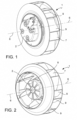
- the keys 10 are formed directly from the hub wall 8 of the impeller 7 and protrude radially inwards ( Figures 3, 4, 5 , 9, 10 ).
- the keys 10 can be made separately from the impeller 7 and then connected to the hub wall 8.
- the first transverse edge 20 and the first stop surface 13 formed thereon face the insertion direction 12.
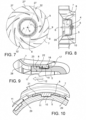
- a radial thickness 22 of the keys 10 protruding from the hub wall 8 is thinner than the radial thickness 23 of the connection wall 5 at the key seats 11, so that the keys 10 can be inserted into the key seats 11 without radially passing through the connection wall 5 ( Figures 9, 10 ).
- the hub wall 8 is preferably formed by a plurality of segments or flaps 21 of a substantially circular cylindrical wall, alternated and spaced apart from one another by gaps or first widening slits 29, and the keys 10 are preferably positioned at a constant angular pitch, for example, four keys 10 are arranged at a 90° pitch, preferably a key 10 positioned at one of the segments or flaps 21 of the substantially circular cylindrical wall, respectively.
- the first widening slits 29 weaken or interrupt the hub wall 8 to allow an elastic widening thereof in the circumferential and/or radial direction with respect to the rotation axis 6.
- the first widening slits 29 can preferably extend in an axial direction, in regions spaced apart from the keys 10 and from the key seats 11, for example, substantially halfway between two consecutive keys 10, respectively.
- the keys 10 can be arranged flush with a rear edge 24 of the hub wall 8 opposite to the transverse edge 20 of the keys 10 ( Figures 4, 5 ).
- the hub wall 8 can form a tubular lead-in portion 28 ( Figure 9 ) which widens radially, preferably by means of a gradual continuous curvature, on one side of the impeller 7 facing the insertion direction 12 or, in other words, on the same side as the first transverse edges 20 of the keys 10.
- This lead-in (or flaring) portion 28 of the hub wall 8 forms a lead-in for a guided insertion of the hub wall 8 onto the connection wall 5 of the rotor 1.
- the keys 10 have a plate-like shape with a thickness (measured in the radial direction with respect to the rotation axis 6) tapered in the insertion direction 12 ( Figure 9 ), thus facilitating the insertion of the hub wall 8 of the impeller 7 onto the connection wall 5 of the rotor 1.
- the key seats 11 can be non-through cavities or through openings (in the radial direction) delimited by two second opposite longitudinal edges 25, extending substantially parallel to the rotation axis 6 or substantially in the insertion direction 12, preferably but not necessarily parallel to one another, and which form the aforesaid second side surfaces 16, as well as with at least a second transverse edge 26 extending in a direction transverse to the insertion direction 12 and forming the aforesaid second stop surface 14.
- the second longitudinal edges 25, and therefore the second side surfaces 16 of the key seat 10 approach each other going towards the second transverse edge 26 or extend along parallel directions with respect to the rotation axis 6.
- the second longitudinal edges 25 can substantially be rectilinear and the second transverse edge 26 can be planar and arc-shaped along a circumference with respect to the rotation axis 6.
- the second transverse edge 26 connects to the second longitudinal edges 25 and, along with the second longitudinal edges 25, results in a U-shaped inner contour of the key seat 11 ( Figures 4, 5 ), which is substantially complementary to the shape of the U-shaped outer contour of the key 10.
- This shape of the key seat 11 can be easily achieved by injection molding and facilitates the insertion of the key 10 into the key seat 11 in the direction of the rotation axis 6.
- the key seats 11 are formed by the connection wall 5 of the rotor 4 ( Figures 3, 4 , 9 ).
- the second transverse edge 26 and the second stop surface 14 formed thereon are positioned on one side of the key seat 11 opposite to the insertion direction 12 but facing the insertion direction 12.
- the key seats 11 can be formed in a portion of the connection wall 5 which is preferably circular cylindrical.
- the key seats 11 can be positioned at a constant angular pitch, for example four key seats 11 arranged at a 90° pitch.
- the coupling portions 17 comprise a plurality of flanges 31 protruding from the hub wall 8 radially inwards, so as to snap-engage corresponding counter-flanges 30 of the connection wall 5 which form the counter-coupling portions 18 ( Figure 9 ).
- the flanges 31 are formed directly on the keys 10 on an opposite side to the first transverse edge 20 of the first stop surface 13, and facing in the opposite direction to the insertion direction 12.
- the counter-flanges 30 are instead formed directly in the key seats 11 on an opposite side to the second transverse edge 26 or the second stop surface 14, and facing the insertion direction 12.
- connection wall 5 and the hub wall 8 are mutually engaged in pressing contact with an elastic preload due to an elastic deformation of the hub wall 8.
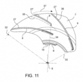
- the impeller 7 forms a plurality of main blades 27 arranged in a circumferential sequence and alternated to secondary blades (splits) 27' of a shorter length than the length of the main blades 27 ( Figures 7 , 11 ).
- the length of the main blades 27 is equal to or greater than twice the length of the secondary blades (splits) 27'.
- Both the main blades 27 and the secondary blades (splits) 27' extend up to the same outer diameter (or circumference) 32 of the impeller 7, but a radially inner end of the primary blades 27 is positioned at a first radial distance 33 from the rotation axis 6 while a radially inner end of the secondary blades 27' is positioned at a second radial distance 34 from the rotation axis 6 which is greater than the first radial distance 33.
- the secondary blades (splits) 27' are not equally spaced apart from the two adjacent primary blades 27 ( Figure 11 ). With respect to a central, equally spaced apart position 35, the secondary blade 27' is offset or moved towards the adjacent frontal main blade 36 with reference to the rotation direction 37 ( Figure 11 ).
- the invention also relates to a heat pump (not shown in the Figures since it is known per se) comprising the motor-fan assembly 1, in particular associated with a heat exchanger of a compressor and/or evaporator of the heat pump.
Landscapes
- Engineering & Computer Science (AREA)
- Mechanical Engineering (AREA)
- General Engineering & Computer Science (AREA)
- Structures Of Non-Positive Displacement Pumps (AREA)
- Cookers (AREA)
- Food-Manufacturing Devices (AREA)
- Control Of Multiple Motors (AREA)
Applications Claiming Priority (1)
| Application Number | Priority Date | Filing Date | Title |
|---|---|---|---|
| IT202021000004088U IT202100004088U1 (it) | 2021-08-06 | 2021-08-06 | Gruppo motore-ventilatore |
Publications (3)
| Publication Number | Publication Date |
|---|---|
| EP4130482A1 true EP4130482A1 (de) | 2023-02-08 |
| EP4130482C0 EP4130482C0 (de) | 2025-06-25 |
| EP4130482B1 EP4130482B1 (de) | 2025-06-25 |
Family
ID=83319177
Family Applications (1)
| Application Number | Title | Priority Date | Filing Date |
|---|---|---|---|
| EP22188355.6A Active EP4130482B1 (de) | 2021-08-06 | 2022-08-02 | Motorgebläsegruppe |
Country Status (3)
| Country | Link |
|---|---|
| EP (1) | EP4130482B1 (de) |
| ES (1) | ES3042355T3 (de) |
| IT (1) | IT202100004088U1 (de) |
Citations (4)
| Publication number | Priority date | Publication date | Assignee | Title |
|---|---|---|---|---|
| DE19829070A1 (de) * | 1998-06-30 | 2000-01-05 | Atlas Copco Electric Tools | Rotationsmaschine |
| US20150125326A1 (en) * | 2012-03-22 | 2015-05-07 | Valeo Systemes Thermiques | Ventilation System |
| US20150176587A1 (en) * | 2013-12-20 | 2015-06-25 | Nidec Corporation | Fan |
| CN205744589U (zh) * | 2016-05-06 | 2016-11-30 | 宁波方太厨具有限公司 | 一种快速拆装的离心风机叶轮 |
-
2021
- 2021-08-06 IT IT202021000004088U patent/IT202100004088U1/it unknown
-
2022
- 2022-08-02 EP EP22188355.6A patent/EP4130482B1/de active Active
- 2022-08-02 ES ES22188355T patent/ES3042355T3/es active Active
Patent Citations (4)
| Publication number | Priority date | Publication date | Assignee | Title |
|---|---|---|---|---|
| DE19829070A1 (de) * | 1998-06-30 | 2000-01-05 | Atlas Copco Electric Tools | Rotationsmaschine |
| US20150125326A1 (en) * | 2012-03-22 | 2015-05-07 | Valeo Systemes Thermiques | Ventilation System |
| US20150176587A1 (en) * | 2013-12-20 | 2015-06-25 | Nidec Corporation | Fan |
| CN205744589U (zh) * | 2016-05-06 | 2016-11-30 | 宁波方太厨具有限公司 | 一种快速拆装的离心风机叶轮 |
Also Published As
| Publication number | Publication date |
|---|---|
| IT202100004088U1 (it) | 2023-02-06 |
| EP4130482C0 (de) | 2025-06-25 |
| ES3042355T3 (en) | 2025-11-20 |
| EP4130482B1 (de) | 2025-06-25 |
Similar Documents
| Publication | Publication Date | Title |
|---|---|---|
| EP3618240B1 (de) | Gebläsemotor und herstellungsverfahren dafür | |
| US6445098B1 (en) | Can for a synthetic pump motor | |
| CN113339320A (zh) | 叶轮及其制造方法 | |
| JP2013064502A (ja) | 軸受けケージ | |
| US11927099B2 (en) | Composite seal structure for a machine, and method of manufacturing the composite seal structure | |
| WO2023161849A1 (en) | Quick connector with verification | |
| EP4130482A1 (de) | Motorgebläsegruppe | |
| US20180258948A1 (en) | Centrifugal blower assemblies having a plurality of airflow guidance fins and method of assembling the same | |
| JP2006518023A (ja) | スペーサ部材を備えたスラスト軸受 | |
| US9651057B2 (en) | Blower assembly including a noise attenuating impeller and method for assembling the same | |
| JP6999068B2 (ja) | シールリング | |
| US20260022755A1 (en) | Anti-vibration ring and motor assembly | |
| EP2365224B1 (de) | Radialer Förderer für Absaughaube | |
| US7938584B2 (en) | Cage for inclined ball bearing | |
| JP2018523776A (ja) | 長手方向シール部材および環状シール部材を備える真空ポンプ | |
| US8616844B2 (en) | Fan and shroud assembly | |
| US7854588B2 (en) | Stamped torque converter stator blades and a torque converter stator with stamped blades | |
| US12168986B2 (en) | Self-priming assembly for use in a multi-stage pump | |
| CN107489840B (zh) | 管路接头、压力管、发动机和车辆 | |
| JP4580711B2 (ja) | 電気モータ式燃料ポンプ | |
| ES2885103T3 (es) | Montaje de ventilador | |
| EP2923096B1 (de) | Lagerschale mit ausrichtungsprojektionsmerkmal | |
| US11193500B2 (en) | Blower device | |
| US12486934B2 (en) | Plug-in insert | |
| US20230243362A1 (en) | Blower |
Legal Events
| Date | Code | Title | Description |
|---|---|---|---|
| PUAI | Public reference made under article 153(3) epc to a published international application that has entered the european phase |
Free format text: ORIGINAL CODE: 0009012 |
|
| STAA | Information on the status of an ep patent application or granted ep patent |
Free format text: STATUS: THE APPLICATION HAS BEEN PUBLISHED |
|
| AK | Designated contracting states |
Kind code of ref document: A1 Designated state(s): AL AT BE BG CH CY CZ DE DK EE ES FI FR GB GR HR HU IE IS IT LI LT LU LV MC MK MT NL NO PL PT RO RS SE SI SK SM TR |
|
| P01 | Opt-out of the competence of the unified patent court (upc) registered |
Effective date: 20230518 |
|
| STAA | Information on the status of an ep patent application or granted ep patent |
Free format text: STATUS: REQUEST FOR EXAMINATION WAS MADE |
|
| 17P | Request for examination filed |
Effective date: 20230728 |
|
| RBV | Designated contracting states (corrected) |
Designated state(s): AL AT BE BG CH CY CZ DE DK EE ES FI FR GB GR HR HU IE IS IT LI LT LU LV MC MK MT NL NO PL PT RO RS SE SI SK SM TR |
|
| GRAP | Despatch of communication of intention to grant a patent |
Free format text: ORIGINAL CODE: EPIDOSNIGR1 |
|
| STAA | Information on the status of an ep patent application or granted ep patent |
Free format text: STATUS: GRANT OF PATENT IS INTENDED |
|
| INTG | Intention to grant announced |
Effective date: 20250408 |
|
| GRAS | Grant fee paid |
Free format text: ORIGINAL CODE: EPIDOSNIGR3 |
|
| GRAA | (expected) grant |
Free format text: ORIGINAL CODE: 0009210 |
|
| STAA | Information on the status of an ep patent application or granted ep patent |
Free format text: STATUS: THE PATENT HAS BEEN GRANTED |
|
| AK | Designated contracting states |
Kind code of ref document: B1 Designated state(s): AL AT BE BG CH CY CZ DE DK EE ES FI FR GB GR HR HU IE IS IT LI LT LU LV MC MK MT NL NO PL PT RO RS SE SI SK SM TR |
|
| REG | Reference to a national code |
Ref country code: GB Ref legal event code: FG4D |
|
| REG | Reference to a national code |
Ref country code: CH Ref legal event code: EP |
|
| REG | Reference to a national code |
Ref country code: CH Ref legal event code: EP |
|
| REG | Reference to a national code |
Ref country code: IE Ref legal event code: FG4D |
|
| REG | Reference to a national code |
Ref country code: DE Ref legal event code: R096 Ref document number: 602022016336 Country of ref document: DE |
|
| U01 | Request for unitary effect filed |
Effective date: 20250724 |
|
| U07 | Unitary effect registered |
Designated state(s): AT BE BG DE DK EE FI FR IT LT LU LV MT NL PT RO SE SI Effective date: 20250731 |
|
| P04 | Withdrawal of opt-out of the competence of the unified patent court (upc) registered |
Free format text: CASE NUMBER: UPC_APP_203538_1/2023 Effective date: 20250731 |
|
| U20 | Renewal fee for the european patent with unitary effect paid |
Year of fee payment: 4 Effective date: 20250825 |
|
| PGFP | Annual fee paid to national office [announced via postgrant information from national office to epo] |
Ref country code: ES Payment date: 20250909 Year of fee payment: 4 |
|
| PG25 | Lapsed in a contracting state [announced via postgrant information from national office to epo] |
Ref country code: NO Free format text: LAPSE BECAUSE OF FAILURE TO SUBMIT A TRANSLATION OF THE DESCRIPTION OR TO PAY THE FEE WITHIN THE PRESCRIBED TIME-LIMIT Effective date: 20250925 Ref country code: GR Free format text: LAPSE BECAUSE OF FAILURE TO SUBMIT A TRANSLATION OF THE DESCRIPTION OR TO PAY THE FEE WITHIN THE PRESCRIBED TIME-LIMIT Effective date: 20250926 |
|
| PG25 | Lapsed in a contracting state [announced via postgrant information from national office to epo] |
Ref country code: HR Free format text: LAPSE BECAUSE OF FAILURE TO SUBMIT A TRANSLATION OF THE DESCRIPTION OR TO PAY THE FEE WITHIN THE PRESCRIBED TIME-LIMIT Effective date: 20250625 |
|
| PG25 | Lapsed in a contracting state [announced via postgrant information from national office to epo] |
Ref country code: RS Free format text: LAPSE BECAUSE OF FAILURE TO SUBMIT A TRANSLATION OF THE DESCRIPTION OR TO PAY THE FEE WITHIN THE PRESCRIBED TIME-LIMIT Effective date: 20250925 |
|
| REG | Reference to a national code |
Ref country code: ES Ref legal event code: FG2A Ref document number: 3042355 Country of ref document: ES Kind code of ref document: T3 Effective date: 20251120 |
|
| PG25 | Lapsed in a contracting state [announced via postgrant information from national office to epo] |
Ref country code: IS Free format text: LAPSE BECAUSE OF FAILURE TO SUBMIT A TRANSLATION OF THE DESCRIPTION OR TO PAY THE FEE WITHIN THE PRESCRIBED TIME-LIMIT Effective date: 20251025 |
|
| PG25 | Lapsed in a contracting state [announced via postgrant information from national office to epo] |
Ref country code: SM Free format text: LAPSE BECAUSE OF FAILURE TO SUBMIT A TRANSLATION OF THE DESCRIPTION OR TO PAY THE FEE WITHIN THE PRESCRIBED TIME-LIMIT Effective date: 20250625 |
|
| PG25 | Lapsed in a contracting state [announced via postgrant information from national office to epo] |
Ref country code: CZ Free format text: LAPSE BECAUSE OF FAILURE TO SUBMIT A TRANSLATION OF THE DESCRIPTION OR TO PAY THE FEE WITHIN THE PRESCRIBED TIME-LIMIT Effective date: 20250625 |
|
| PG25 | Lapsed in a contracting state [announced via postgrant information from national office to epo] |
Ref country code: PL Free format text: LAPSE BECAUSE OF FAILURE TO SUBMIT A TRANSLATION OF THE DESCRIPTION OR TO PAY THE FEE WITHIN THE PRESCRIBED TIME-LIMIT Effective date: 20250625 |
|
| PG25 | Lapsed in a contracting state [announced via postgrant information from national office to epo] |
Ref country code: SK Free format text: LAPSE BECAUSE OF FAILURE TO SUBMIT A TRANSLATION OF THE DESCRIPTION OR TO PAY THE FEE WITHIN THE PRESCRIBED TIME-LIMIT Effective date: 20250625 |
|
| REG | Reference to a national code |
Ref country code: CH Ref legal event code: H13 Free format text: ST27 STATUS EVENT CODE: U-0-0-H10-H13 (AS PROVIDED BY THE NATIONAL OFFICE) Effective date: 20260324 |
|
| PG25 | Lapsed in a contracting state [announced via postgrant information from national office to epo] |
Ref country code: MC Free format text: LAPSE BECAUSE OF FAILURE TO SUBMIT A TRANSLATION OF THE DESCRIPTION OR TO PAY THE FEE WITHIN THE PRESCRIBED TIME-LIMIT Effective date: 20250625 |
|
| PG25 | Lapsed in a contracting state [announced via postgrant information from national office to epo] |
Ref country code: CH Free format text: LAPSE BECAUSE OF NON-PAYMENT OF DUE FEES Effective date: 20250831 |
|
| PLBE | No opposition filed within time limit |
Free format text: ORIGINAL CODE: 0009261 |
|
| STAA | Information on the status of an ep patent application or granted ep patent |
Free format text: STATUS: NO OPPOSITION FILED WITHIN TIME LIMIT |