EP4130493B1 - Agencement de commande hydraulique - Google Patents
Agencement de commande hydraulique Download PDFInfo
- Publication number
- EP4130493B1 EP4130493B1 EP22186950.6A EP22186950A EP4130493B1 EP 4130493 B1 EP4130493 B1 EP 4130493B1 EP 22186950 A EP22186950 A EP 22186950A EP 4130493 B1 EP4130493 B1 EP 4130493B1
- Authority
- EP
- European Patent Office
- Prior art keywords
- valve
- pressure
- control
- proportional valve
- control assembly
- Prior art date
- Legal status (The legal status is an assumption and is not a legal conclusion. Google has not performed a legal analysis and makes no representation as to the accuracy of the status listed.)
- Active
Links
Images
Classifications
-
- F—MECHANICAL ENGINEERING; LIGHTING; HEATING; WEAPONS; BLASTING
- F15—FLUID-PRESSURE ACTUATORS; HYDRAULICS OR PNEUMATICS IN GENERAL
- F15B—SYSTEMS ACTING BY MEANS OF FLUIDS IN GENERAL; FLUID-PRESSURE ACTUATORS, e.g. SERVOMOTORS; DETAILS OF FLUID-PRESSURE SYSTEMS, NOT OTHERWISE PROVIDED FOR
- F15B11/00—Servomotor systems without provision for follow-up action; Circuits therefor
- F15B11/02—Systems essentially incorporating special features for controlling the speed or actuating force of an output member
- F15B11/024—Systems essentially incorporating special features for controlling the speed or actuating force of an output member by means of differential connection of the servomotor lines, e.g. regenerative circuits
-
- F—MECHANICAL ENGINEERING; LIGHTING; HEATING; WEAPONS; BLASTING
- F15—FLUID-PRESSURE ACTUATORS; HYDRAULICS OR PNEUMATICS IN GENERAL
- F15B—SYSTEMS ACTING BY MEANS OF FLUIDS IN GENERAL; FLUID-PRESSURE ACTUATORS, e.g. SERVOMOTORS; DETAILS OF FLUID-PRESSURE SYSTEMS, NOT OTHERWISE PROVIDED FOR
- F15B11/00—Servomotor systems without provision for follow-up action; Circuits therefor
- F15B11/02—Systems essentially incorporating special features for controlling the speed or actuating force of an output member
- F15B11/04—Systems essentially incorporating special features for controlling the speed or actuating force of an output member for controlling the speed
- F15B11/042—Systems essentially incorporating special features for controlling the speed or actuating force of an output member for controlling the speed by means in the feed line, i.e. "meter in"
-
- F—MECHANICAL ENGINEERING; LIGHTING; HEATING; WEAPONS; BLASTING
- F15—FLUID-PRESSURE ACTUATORS; HYDRAULICS OR PNEUMATICS IN GENERAL
- F15B—SYSTEMS ACTING BY MEANS OF FLUIDS IN GENERAL; FLUID-PRESSURE ACTUATORS, e.g. SERVOMOTORS; DETAILS OF FLUID-PRESSURE SYSTEMS, NOT OTHERWISE PROVIDED FOR
- F15B11/00—Servomotor systems without provision for follow-up action; Circuits therefor
- F15B11/02—Systems essentially incorporating special features for controlling the speed or actuating force of an output member
- F15B11/04—Systems essentially incorporating special features for controlling the speed or actuating force of an output member for controlling the speed
- F15B11/044—Systems essentially incorporating special features for controlling the speed or actuating force of an output member for controlling the speed by means in the return line, i.e. "meter out"
-
- F—MECHANICAL ENGINEERING; LIGHTING; HEATING; WEAPONS; BLASTING
- F15—FLUID-PRESSURE ACTUATORS; HYDRAULICS OR PNEUMATICS IN GENERAL
- F15B—SYSTEMS ACTING BY MEANS OF FLUIDS IN GENERAL; FLUID-PRESSURE ACTUATORS, e.g. SERVOMOTORS; DETAILS OF FLUID-PRESSURE SYSTEMS, NOT OTHERWISE PROVIDED FOR
- F15B2211/00—Circuits for servomotor systems
- F15B2211/30—Directional control
- F15B2211/305—Directional control characterised by the type of valves
- F15B2211/30505—Non-return valves, i.e. check valves
-
- F—MECHANICAL ENGINEERING; LIGHTING; HEATING; WEAPONS; BLASTING
- F15—FLUID-PRESSURE ACTUATORS; HYDRAULICS OR PNEUMATICS IN GENERAL
- F15B—SYSTEMS ACTING BY MEANS OF FLUIDS IN GENERAL; FLUID-PRESSURE ACTUATORS, e.g. SERVOMOTORS; DETAILS OF FLUID-PRESSURE SYSTEMS, NOT OTHERWISE PROVIDED FOR
- F15B2211/00—Circuits for servomotor systems
- F15B2211/30—Directional control
- F15B2211/305—Directional control characterised by the type of valves
- F15B2211/30505—Non-return valves, i.e. check valves
- F15B2211/3051—Cross-check valves
-
- F—MECHANICAL ENGINEERING; LIGHTING; HEATING; WEAPONS; BLASTING
- F15—FLUID-PRESSURE ACTUATORS; HYDRAULICS OR PNEUMATICS IN GENERAL
- F15B—SYSTEMS ACTING BY MEANS OF FLUIDS IN GENERAL; FLUID-PRESSURE ACTUATORS, e.g. SERVOMOTORS; DETAILS OF FLUID-PRESSURE SYSTEMS, NOT OTHERWISE PROVIDED FOR
- F15B2211/00—Circuits for servomotor systems
- F15B2211/30—Directional control
- F15B2211/305—Directional control characterised by the type of valves
- F15B2211/3056—Assemblies of multiple valves
- F15B2211/30565—Assemblies of multiple valves having multiple valves for a single output member, e.g. for creating higher valve function by use of multiple valves like two 2/2-valves replacing a 5/3-valve
- F15B2211/3058—Assemblies of multiple valves having multiple valves for a single output member, e.g. for creating higher valve function by use of multiple valves like two 2/2-valves replacing a 5/3-valve having additional valves for interconnecting the fluid chambers of a double-acting actuator, e.g. for regeneration mode or for floating mode
-
- F—MECHANICAL ENGINEERING; LIGHTING; HEATING; WEAPONS; BLASTING
- F15—FLUID-PRESSURE ACTUATORS; HYDRAULICS OR PNEUMATICS IN GENERAL
- F15B—SYSTEMS ACTING BY MEANS OF FLUIDS IN GENERAL; FLUID-PRESSURE ACTUATORS, e.g. SERVOMOTORS; DETAILS OF FLUID-PRESSURE SYSTEMS, NOT OTHERWISE PROVIDED FOR
- F15B2211/00—Circuits for servomotor systems
- F15B2211/30—Directional control
- F15B2211/31—Directional control characterised by the positions of the valve element
- F15B2211/3105—Neutral or centre positions
- F15B2211/3111—Neutral or centre positions the pump port being closed in the centre position, e.g. so-called closed centre
-
- F—MECHANICAL ENGINEERING; LIGHTING; HEATING; WEAPONS; BLASTING
- F15—FLUID-PRESSURE ACTUATORS; HYDRAULICS OR PNEUMATICS IN GENERAL
- F15B—SYSTEMS ACTING BY MEANS OF FLUIDS IN GENERAL; FLUID-PRESSURE ACTUATORS, e.g. SERVOMOTORS; DETAILS OF FLUID-PRESSURE SYSTEMS, NOT OTHERWISE PROVIDED FOR
- F15B2211/00—Circuits for servomotor systems
- F15B2211/30—Directional control
- F15B2211/31—Directional control characterised by the positions of the valve element
- F15B2211/3122—Special positions other than the pump port being connected to working ports or the working ports being connected to the return line
- F15B2211/3127—Floating position connecting the working ports and the return line
-
- F—MECHANICAL ENGINEERING; LIGHTING; HEATING; WEAPONS; BLASTING
- F15—FLUID-PRESSURE ACTUATORS; HYDRAULICS OR PNEUMATICS IN GENERAL
- F15B—SYSTEMS ACTING BY MEANS OF FLUIDS IN GENERAL; FLUID-PRESSURE ACTUATORS, e.g. SERVOMOTORS; DETAILS OF FLUID-PRESSURE SYSTEMS, NOT OTHERWISE PROVIDED FOR
- F15B2211/00—Circuits for servomotor systems
- F15B2211/30—Directional control
- F15B2211/32—Directional control characterised by the type of actuation
- F15B2211/329—Directional control characterised by the type of actuation actuated by fluid pressure
-
- F—MECHANICAL ENGINEERING; LIGHTING; HEATING; WEAPONS; BLASTING
- F15—FLUID-PRESSURE ACTUATORS; HYDRAULICS OR PNEUMATICS IN GENERAL
- F15B—SYSTEMS ACTING BY MEANS OF FLUIDS IN GENERAL; FLUID-PRESSURE ACTUATORS, e.g. SERVOMOTORS; DETAILS OF FLUID-PRESSURE SYSTEMS, NOT OTHERWISE PROVIDED FOR
- F15B2211/00—Circuits for servomotor systems
- F15B2211/30—Directional control
- F15B2211/35—Directional control combined with flow control
- F15B2211/351—Flow control by regulating means in feed line, i.e. meter-in control
-
- F—MECHANICAL ENGINEERING; LIGHTING; HEATING; WEAPONS; BLASTING
- F15—FLUID-PRESSURE ACTUATORS; HYDRAULICS OR PNEUMATICS IN GENERAL
- F15B—SYSTEMS ACTING BY MEANS OF FLUIDS IN GENERAL; FLUID-PRESSURE ACTUATORS, e.g. SERVOMOTORS; DETAILS OF FLUID-PRESSURE SYSTEMS, NOT OTHERWISE PROVIDED FOR
- F15B2211/00—Circuits for servomotor systems
- F15B2211/30—Directional control
- F15B2211/35—Directional control combined with flow control
- F15B2211/353—Flow control by regulating means in return line, i.e. meter-out control
-
- F—MECHANICAL ENGINEERING; LIGHTING; HEATING; WEAPONS; BLASTING
- F15—FLUID-PRESSURE ACTUATORS; HYDRAULICS OR PNEUMATICS IN GENERAL
- F15B—SYSTEMS ACTING BY MEANS OF FLUIDS IN GENERAL; FLUID-PRESSURE ACTUATORS, e.g. SERVOMOTORS; DETAILS OF FLUID-PRESSURE SYSTEMS, NOT OTHERWISE PROVIDED FOR
- F15B2211/00—Circuits for servomotor systems
- F15B2211/60—Circuit components or control therefor
- F15B2211/63—Electronic controllers
- F15B2211/6303—Electronic controllers using input signals
- F15B2211/6336—Electronic controllers using input signals representing a state of the output member, e.g. position, speed or acceleration
-
- F—MECHANICAL ENGINEERING; LIGHTING; HEATING; WEAPONS; BLASTING
- F15—FLUID-PRESSURE ACTUATORS; HYDRAULICS OR PNEUMATICS IN GENERAL
- F15B—SYSTEMS ACTING BY MEANS OF FLUIDS IN GENERAL; FLUID-PRESSURE ACTUATORS, e.g. SERVOMOTORS; DETAILS OF FLUID-PRESSURE SYSTEMS, NOT OTHERWISE PROVIDED FOR
- F15B2211/00—Circuits for servomotor systems
- F15B2211/60—Circuit components or control therefor
- F15B2211/63—Electronic controllers
- F15B2211/6303—Electronic controllers using input signals
- F15B2211/634—Electronic controllers using input signals representing a state of a valve
-
- F—MECHANICAL ENGINEERING; LIGHTING; HEATING; WEAPONS; BLASTING
- F15—FLUID-PRESSURE ACTUATORS; HYDRAULICS OR PNEUMATICS IN GENERAL
- F15B—SYSTEMS ACTING BY MEANS OF FLUIDS IN GENERAL; FLUID-PRESSURE ACTUATORS, e.g. SERVOMOTORS; DETAILS OF FLUID-PRESSURE SYSTEMS, NOT OTHERWISE PROVIDED FOR
- F15B2211/00—Circuits for servomotor systems
- F15B2211/60—Circuit components or control therefor
- F15B2211/665—Methods of control using electronic components
-
- F—MECHANICAL ENGINEERING; LIGHTING; HEATING; WEAPONS; BLASTING
- F15—FLUID-PRESSURE ACTUATORS; HYDRAULICS OR PNEUMATICS IN GENERAL
- F15B—SYSTEMS ACTING BY MEANS OF FLUIDS IN GENERAL; FLUID-PRESSURE ACTUATORS, e.g. SERVOMOTORS; DETAILS OF FLUID-PRESSURE SYSTEMS, NOT OTHERWISE PROVIDED FOR
- F15B2211/00—Circuits for servomotor systems
- F15B2211/60—Circuit components or control therefor
- F15B2211/665—Methods of control using electronic components
- F15B2211/6658—Control using different modes, e.g. four-quadrant-operation, working mode and transportation mode
-
- F—MECHANICAL ENGINEERING; LIGHTING; HEATING; WEAPONS; BLASTING
- F15—FLUID-PRESSURE ACTUATORS; HYDRAULICS OR PNEUMATICS IN GENERAL
- F15B—SYSTEMS ACTING BY MEANS OF FLUIDS IN GENERAL; FLUID-PRESSURE ACTUATORS, e.g. SERVOMOTORS; DETAILS OF FLUID-PRESSURE SYSTEMS, NOT OTHERWISE PROVIDED FOR
- F15B2211/00—Circuits for servomotor systems
- F15B2211/70—Output members, e.g. hydraulic motors or cylinders or control therefor
- F15B2211/705—Output members, e.g. hydraulic motors or cylinders or control therefor characterised by the type of output members or actuators
- F15B2211/7051—Linear output members
- F15B2211/7053—Double-acting output members
-
- F—MECHANICAL ENGINEERING; LIGHTING; HEATING; WEAPONS; BLASTING
- F15—FLUID-PRESSURE ACTUATORS; HYDRAULICS OR PNEUMATICS IN GENERAL
- F15B—SYSTEMS ACTING BY MEANS OF FLUIDS IN GENERAL; FLUID-PRESSURE ACTUATORS, e.g. SERVOMOTORS; DETAILS OF FLUID-PRESSURE SYSTEMS, NOT OTHERWISE PROVIDED FOR
- F15B2211/00—Circuits for servomotor systems
- F15B2211/70—Output members, e.g. hydraulic motors or cylinders or control therefor
- F15B2211/765—Control of position or angle of the output member
Definitions
- the invention relates to a hydraulic control arrangement for actuating a hydraulic actuator/consumer, in particular a differential hydraulic cylinder, according to the preamble of patent claim 1.
- Regeneration is understood to mean a return of fluid from a (piston) rod side of the hydraulic cylinder to a piston side of the hydraulic cylinder by fluidly connecting the two sides to one another.
- a load holding function is understood to mean blocking the movement of a piston of the hydraulic cylinder.
- An internally known control arrangement has a directional control valve that connects two working lines, which are connected to pressure chambers of the actuator (hydraulic cylinder) acting in opposite directions, to a pressure medium source or a pressure medium sink, depending on the switching position.
- a check valve is arranged in each of the two working lines (power pressure lines), which can be unlocked by pressurizing the other working line.
- a load-dependent valve is arranged in a short-circuit line connecting the two working lines, which switches between the functions of load holding and the normal and regeneration circuit. This means that the function switching takes place without electrical control signals.
- the disadvantage of the known control arrangement is that it does not work with switching loads can be used, so that four-quadrant operation is not possible.
- the mutually unlockable check valves cannot have clearly defined circuit states, which severely impairs the control functionality.
- the function switchover of the normal and regeneration circuit must be set mechanically during project planning or during commissioning.
- Another internally known control arrangement also has a directional control valve, which pressurizes or relieves pressure on the two working lines depending on the switching position, as well as a check valve arranged in each of the two working lines.
- a first solenoid valve is used to unlock the check valves and a second solenoid valve is used to short-circuit the two working lines so that the functions of load holding and the normal and regeneration circuit can be switched valve-controlled. This means that the function switching takes place using two electrical control signals.
- the disadvantage of this solution is that two solenoid valves are required, so that this control arrangement is cost-intensive due to the number of solenoid valves and the power electronics required for an output stage for switching.
- the invention is based on the object of providing a hydraulic control arrangement with which the hydraulic functions described can be implemented, but which is at the same time simple, compact and inexpensive.
- the control arrangement according to the invention is used to operate a hydraulic actuator, in particular a differential hydraulic cylinder.
- the control arrangement has two working lines, one of which can be connected to pressure chambers of the actuator acting in opposite directions for actuating the actuator and in each of which an unlockable check valve is arranged, the blocked flow direction of which can be released from the direction of the pressure chambers by hydraulic control becomes.
- the Control arrangement has a proportional valve, through which the two working lines can be connected to a pressure medium source to pressurize the associated pressure chamber with a pressure medium source or to relieve the pressure of the associated pressure chamber with a pressure medium sink, depending on the (switching) position of the proportional valve.
- control arrangement has a short-circuit line which connects the two working lines with the interposition of two check valves with opposite flow directions.
- one of the check valves arranged in the short-circuit line is designed to be lockable and the other of the check valves arranged in the short-circuit line is designed to be unlockable.
- control arrangement has a, preferably magnetically controlled, switching valve, through which the unlockable check valves arranged in the working lines and the lockable check valve arranged in the short-circuit line can be hydraulically controlled in a switching position of the switching valve.
- the control arrangement according to the present invention has a first working line which is connectable (or connected) to a first pressure chamber of an actuator, so that the actuator can be moved by pressurizing the first working line in a first direction, in particular in an extension direction of a hydraulic cylinder, for example of such an actuator, is adjustable, as well as a second working line which can be connected (or is connected) to a second pressure chamber of the actuator, so that the actuator can be moved by pressurizing the second working line in a second direction, in particular a retraction direction of the hydraulic cylinder as an example of such an actuator , is adjustable.
- a first check valve is arranged in the first working line and a second check valve is arranged in the second working line, each of which allows a flow of pressure medium only in the direction of the actuator or the respective pressure chamber and blocks it in a blocking direction/opposite direction/opposite direction.
- the first and second check valves are designed to be unlockable in the sense that the blocking direction is released/unlocked (controlled) when a control port of the respective check valve is pressurized.
- the control arrangement has the proportional valve, which is used to continuously regulate a hydraulic resistance and, depending on the (switching) position, the first working line or second working line for pressurizing with a pump/the Pressure medium source or a tank/the pressure medium sink connects.
- control arrangement has a short-circuit line through which the two working lines are or can be fluidly connected to one another.
- a third check valve arranged in the short-circuit line enables a pressure medium flow in only one flow direction from one working line into the other working line, in particular from the second working line into the first working line, and blocks, in particular, a pressure medium flow in a blocking direction/opposite direction/opposite direction the first work management to the second work management.
- a fourth check valve arranged in the short-circuit line enables a pressure medium flow in only one flow direction from the other working line into one working line, in particular from the first working line into the second working line, and blocks a pressure medium flow in a blocking direction/opposite direction/opposite direction, in particular from the second line into the first line.
- the third check valve is designed to be lockable, i.e. the flow direction is closed/blocked (controlled) when a control port of the third check valve is pressurized.
- the fourth check valve is designed to be unlockable in the sense that the blocking direction is released/unlocked (controlled) when a control port of the fourth check valve is pressurized.
- the control arrangement has a switching valve which controls/switches the first, second and third check valves. This means that in a first switching position the switching valve relieves pressure on the control connections of the first, second and third check valves, i.e. does not control these three check valves (in the above sense), and in a second switching position pressurizes the control connections of the first, second and third check valves, i.e. controls these three check valves (in the above sense).
- control arrangement according to the invention has (only) one switching valve through which three of the four check valves can be controlled hydraulically at the same time.
- the structure of the control arrangement according to the invention has the advantage that the three hydraulic functions of a normal switching/force position control, one Regeneration circuit and load holding can be implemented and at the same time can only be switched between the hydraulic functions in a defined manner using a proportional valve (with integrated controller), a magnetically controlled switching valve and logic elements in the form of lockable/unlockable check valves.
- a proportional valve with integrated controller
- a magnetically controlled switching valve and logic elements in the form of lockable/unlockable check valves.
- the unlockable check valve arranged in the short-circuit line can be hydraulically controlled when a first working line of the two working lines is pressurized. This has the advantage that the pressure caused by frictional force in the first working line can be used to open the unlockable check valve between the two working lines, so that the two working lines can be connected to one another.
- the short-circuit line can be connected to the working lines downstream of the unlockable check valves arranged in the working lines.
- the proportional valve can have a zero position in which the two working lines are pressure-relieved and control positions in which a hydraulic resistance between the working lines on the one hand and the pressure medium source and the pressure medium sink on the other hand can be adjusted. This means that all required hydraulic functions can be implemented with the simply constructed control arrangement.
- a force-position control can be implemented in an actuated switching position of the switching valve and the control positions of the proportional valve
- a regeneration circuit can be implemented in the actuated switching position of the switching valve and the control positions of the proportional valve, and in an unactuated switching position of the switching valve and the Zero position of the proportional valve can be implemented as a load holding function.
- control electronics and power electronics for controlling the proportional valve can be mounted directly on the proportional valve. This allows a particularly compact structure to be implemented.
- the proportional valve can be designed as an integrated axle control valve (IAC valve), so that an already existing component can be used.
- IAC valve integrated axle control valve
- one of the two working lines or both working lines can be connected to the pressure medium sink via a pressure control valve/pressure relief valve.
- the first working line can be connected to the pressure medium sink via a first pressure control valve and/or the second working line can be connected to the pressure medium sink via a second pressure control valve.
- a pressure sensor can be arranged in one of the two working lines or in both working lines. This means that a first pressure sensor is arranged in the first working line and/or a second pressure sensor is arranged in the second working line. By detecting the pressure in the working lines, force-position control can be implemented with the hydraulic control arrangement.
- control arrangement can have a position measuring sensor for detecting the position of the actuator and the proportional valve can have an input for a signal from the position measuring sensor.
- the proportional valve can have a position measuring sensor for detecting the position of a control piston of the proportional valve.
- a position measuring system in which Proportional valve is integrated so that the position data of the control piston can be used for control.
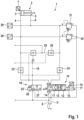
- FIG. 1 a simplified hydraulic circuit diagram of a hydraulic control arrangement.
- Fig. 1 shows a preferred embodiment of a hydraulic control arrangement 1.
- the control arrangement 1 is used to operate a hydraulic actuator 2.
- the actuator 2 which is designed in particular as a differential hydraulic cylinder, can be supplied with pressure medium via a pressure medium source (not shown) and via a pressure medium source (not shown). shown) pressure medium sink can be relieved of pressure.
- a piston-side first pressure chamber 3 of the actuator 2 is connected to a first working line 4 of the control arrangement 1 and a piston rod-side second pressure chamber 5 of the actuator 2 is connected to a second working line 6 of the control arrangement 1.
- the actuator 2 has a displacement sensor 7 for detecting the position of the actuator 2, ie the differential hydraulic cylinder.
- the first working line 4 and the second working line 6 can be connected to the pressure medium source via a pressure connection 8 / P connection of the control arrangement 1 or to the pressure medium sink via a tank connection 9 / T connection of the control arrangement 1.
- the control arrangement 1 has a proportional valve/proportional directional control valve 10, which, depending on the switching position, connects the pressure connection 8 or the tank connection 9 with the first working line 4 (A connection) or with the second working line 6 (B connection).
- a first switching end position 11 of the proportional valve 10 the pressure connection 8 is connected to the first working line 4 and the tank connection 9 is connected to the second working line 6.
- a second switching end position 12 of the proportional valve 10 the tank connection 9 is connected to the first working line 4 and the pressure connection 8 is connected to the second working line 6.
- a switching center position 13 of the proportional valve 10 there is a pressureless circulation between the pressure connection 8 and the tank connection 9, and the first working line 4 and the second working line 6 are relieved towards the tank connection 9.
- the switching center position 13 is a floating position.
- a zero position 14 of the proportional valve 10 the first working line 4 and the second working line 6 are connected to the tank connection 9, and the pressure connection 8 is blocked.
- the zero position 14 is a floating position.
- the proportional valve 10 can be actuated by an electromagnet 15. When unactuated, the proportional valve 10 is in the zero position 14.
- the proportional valve 10 has a position measuring sensor 16 for detecting the position of a control piston of the proportional valve 10.
- the proportional valve 10 has control electronics 17.
- the proportional valve 10 can have an input for a signal from the position measuring sensor 7.
- the control arrangement 1 has a switching valve 18 which, depending on the switching position, connects the pressure connection 8 or the tank connection 9 to a control line 19.
- a switching valve 18 which, depending on the switching position, connects the pressure connection 8 or the tank connection 9 to a control line 19.
- the control line 19 In a first switching position 20 of the switching valve 18, the control line 19 is connected to the tank connection 9.
- a second switching position 21 of the switching valve 18, the control line 19 is connected to the pressure connection 8.
- the switching valve 18 can be actuated by an electromagnet 22. When not actuated, the switching valve 18 is in the first switching position 20.
- a first check valve 23 is arranged in the first working line 4 and is arranged between the proportional valve 10 and the actuator 2.
- the first check valve 23 enables a flow of pressure medium towards the actuator 2/from the proportional valve 10 and blocks a flow of pressure medium from the actuator 2/back to the proportional valve 10.
- the first check valve 23 is designed to be switchable/controllable.
- the first check valve 23 can be controlled hydraulically through the control line 19, i.e. through the switching valve 18.
- the first check valve 23 can be unlocked, so that closing is prevented when hydraulically controlled.
- a second check valve 24 is arranged in the second working line 6 and is arranged between the proportional valve 10 and the actuator 2.
- the second check valve 24 enables a flow of pressure medium in the direction of the actuator 2/from the proportional valve 10 and blocks a flow of pressure medium in the direction out of the actuator 2/back to the proportional valve 10.
- the second check valve 24 is designed to be switchable/controllable.
- the second check valve 24 can be controlled hydraulically through the control line 19, ie through the switching valve 18.
- the Second check valve 24 can be unlocked, so that closing is prevented when hydraulic control is used.
- the control arrangement 1 has a short-circuit line 25, which connects the first working line 4 to the second working line 6.
- the short-circuit line 25 is connected downstream of the first check valve 23 to the first working line 4 and connected downstream of the second check valve 24 to the second working line 6.
- a third check valve 26 is arranged in the short-circuit line 25, which enables a pressure medium flow in the direction of the second working line 6 and blocks it in the direction back into the second working line 6.
- the third check valve 26 is designed to be switchable/controllable.
- the third check valve 26 can be controlled hydraulically through the control line 19, i.e. through the switching valve 18.
- the third check valve 26 can be locked so that opening is prevented when hydraulic control is used.
- a fourth check valve 27 is arranged in the short-circuit line 25, which enables a flow of pressure medium in the direction of the first working line 4 and blocks it in the direction back into the first working line 4.
- the fourth check valve 27 is designed to be switchable/controllable.
- the fourth check valve 27 can be controlled hydraulically by the first working line 4.
- the fourth check valve 27 can be unlocked, so that closing is prevented when hydraulically controlled.
- control arrangement 1 has a first pressure sensor 28 connected to the first working line 4 and a second pressure sensor 29 connected to the second working line 6. Furthermore, the control arrangement 1 has a first pressure relief valve 30 connecting the first working line 4 to the tank connection 9 and a second pressure relief valve 31 connecting the second working line 6 to the tank connection 9.
- the hydraulic control arrangement 1 works according to the following mode of operation: In a first operating state, a hydraulic function of a regeneration circuit is realized, in which the hydraulic cylinder extends and the two pressure chambers 3, 5 of the hydraulic cylinder are hydraulically connected via the short-circuit line 25.
- the proportional valve 1 is in control, that is, the proportional valve 10 connects the pressure connection 8 with the first working line 4, and the switching valve 18 is closed, ie in its first switching position 20.
- the hydraulic cylinder moves out and can be regulated by means of force-position control through the proportional valve 10, while by the pressure caused by friction in the first working line 4 or the first pressure chamber 3 the unlockable fourth check valve 27 is opened between in the short-circuit line 25, so that the first working line 4 and the second working line 6 are connected to one another and the hydraulic cylinder can extend at a higher speed.
- a hydraulic force-position control function is implemented.
- the proportional valve 1 is in control, i.e. that the proportional valve 10 is not in the zero position 14, and the switching valve 18 is open, i.e. in its second switching position 21.
- the force-position control is carried out by the proportional valve 10, in particular also by the Distance measuring sensor 16 and the input for the signal of the distance measuring sensor 7.
- the lockable third check valve 26 is hydraulically controlled by the switching valve 18, so that the first working line 4 and the second working line 6 are separated from one another.
- the unlockable first check valve 23 and the unlockable second check valve 24 are hydraulically controlled by the switching valve 18, so that they are open in a defined manner and four-quadrant operation is possible.
- a hydraulic function of a load holding circuit is implemented.
- the proportional valve 1 is not in control, i.e. that the proportional valve 10 is in the zero position 14, and the switching valve 18 is closed, i.e. in a first switching position 20.
- the check valves 23, 24, 26, 27 are not hydraulically controlled and are located in their basic position. The connection between the first working line 4 and the second working line 6 is closed in a defined manner and the unlockable first check valve 23 and the unlockable second check valves 24 are closed in a defined manner by the load.
- the check valves 23, 24, 26, 27 are preferably designed in a seat valve design, so that no leakage and therefore no gradual hydraulic cylinder movement is possible.
Landscapes
- Engineering & Computer Science (AREA)
- Physics & Mathematics (AREA)
- Fluid Mechanics (AREA)
- Mechanical Engineering (AREA)
- General Engineering & Computer Science (AREA)
- Fluid-Pressure Circuits (AREA)
Claims (10)
- Agencement de commande hydraulique (1) permettant d'actionner un actionneur hydraulique (2), en particulier un vérin hydraulique différentiel, comprenantdeux conduites de travail (4, 6) dont respectivement l'une peut, pour l'actionnement de l'actionneur (2), être reliée à des chambres de pression (3, 5) de l'actionneur (2), agissant dans des sens opposés et dans lesquelles est disposé respectivement un clapet antiretour (23, 24) déverrouillable de manière contrôlée dont le sens d'écoulement verrouillé peut être libéré du côté des chambres de pression (3, 5) par pilotage hydraulique ; une vanne proportionnelle (10) qui permet de relier les deux conduites de travail (4, 6) respectivement en fonction de la position de la vanne proportionnelle (10) à une source de fluide sous pression pour la mise sous pression de la chambre de pression (3, 5) associée, ou à un collecteur de fluide sous pression pour la décompression de la chambre de pression (3, 5) associée ; etune conduite de court-circuit (25) qui relie entre elles les deux conduites de travail (4, 6) en interposant deux clapets antiretour (26, 27) présentant des sens d'écoulement opposés,caractérisé en ce queledit un des clapets antiretour (26) disposés dans la conduite de court-circuit (25) est réalisé en étant verrouillable de manière contrôlée, et ledit autre des clapets antiretour (27) disposés dans la conduite de court-circuit (25) est réalisé en étant déverrouillable de manière contrôlée, etl'agencement de commande présente une vanne de commutation (18) qui pilote hydrauliquement les clapets antiretour (23, 24) déverrouillables de manière contrôlée et disposés dans les conduites de travail (4, 6), ainsi que ledit un clapet antiretour (26) verrouillable de manière contrôlée et disposé dans la conduite de court-circuit (25), dans une seule position de commutation (21) de la vanne de commutation (18).
- Agencement de commande (1) selon la revendication 1, caractérisé en ce que le clapet antiretour (27) déverrouillable de manière contrôlée et disposé dans la conduite de court-circuit (25) est piloté hydrauliquement en cas de mise sous pression d'une première conduite de travail (4) des deux conduites de travail (4, 6).
- Agencement de commande (1) selon la revendication 1 ou 2, caractérisé en ce que la conduite de court-circuit (25) est reliée aux conduites de travail (4, 6) en aval des clapets antiretour (23, 24) déverrouillables de manière contrôlée et disposés dans les conduites de travail (4, 6).
- Agencement de commande (1) selon l'une quelconque des revendications 1 à 3, caractérisé en ce que la vanne proportionnelle présente une position neutre (14) dans laquelle les deux conduites de travail (4, 6) sont décompressées, et des positions de réglage (11, 12, 13) dans lesquelles une résistance hydraulique entre les conduites de travail (4, 6) d'une part et la source de fluide sous pression d'autre part est réglable.
- Agencement de commande (1) selon la revendication 4, caractérisé en ce qu'une régulation force/position est réalisée dans une position de commutation (21) actionnée de la vanne de commutation (18) et les positions de réglage (11, 12, 13) de la vanne proportionnelle (10), une commutation de régénération est réalisée dans la position de commutation (21) actionnée de la vanne de commutation (18) et les positions de réglage (11, 12, 13) de la vanne proportionnelle (10), et une fonction de maintien de charge est réalisée dans une position de commutation (20) non actionnée de la vanne de commutation (18) et la position neutre (14) de la vanne proportionnelle (10).
- Agencement de commande (1) selon l'une quelconque des revendications 1 à 5, caractérisé en ce qu'une électronique de réglage et une électronique de puissance pour commander la vanne proportionnelle (10) sont montées directement sur la vanne proportionnelle (10).
- Agencement de commande (1) selon l'une quelconque des revendications 1 à 6, caractérisé en ce que l'une des deux conduites de travail (4, 6) ou les deux conduites de travail (4, 6) peuvent être reliées au collecteur de fluide sous pression par l'intermédiaire d'une vanne de réglage de pression (30, 31).
- Agencement (1) selon l'une quelconque des revendications 1 à 7, caractérisé en ce qu'un capteur de pression (28, 29) est disposé dans l'une des deux conduites de travail (4, 6) ou dans les deux conduites de travail (4, 6).
- Agencement de commande (1) selon l'une quelconque des revendications 1 à 8, caractérisé en ce que l'agencement de commande présente un capteur de position (7) pour détecter la position de l'actionneur (2), et la vanne proportionnelle (10) présente une entrée pour un signal du capteur de position (7).
- Agencement (1) selon l'une quelconque des revendications 1 à 9, caractérisé en ce que la vanne proportionnelle (10) présente un capteur de position (16) pour détecter la position d'un piston de commande de la vanne proportionnelle (10).
Applications Claiming Priority (1)
| Application Number | Priority Date | Filing Date | Title |
|---|---|---|---|
| DE102021208330.7A DE102021208330B3 (de) | 2021-08-02 | 2021-08-02 | Hydraulische Steueranordnung |
Publications (2)
| Publication Number | Publication Date |
|---|---|
| EP4130493A1 EP4130493A1 (fr) | 2023-02-08 |
| EP4130493B1 true EP4130493B1 (fr) | 2024-03-27 |
Family
ID=82742616
Family Applications (1)
| Application Number | Title | Priority Date | Filing Date |
|---|---|---|---|
| EP22186950.6A Active EP4130493B1 (fr) | 2021-08-02 | 2022-07-26 | Agencement de commande hydraulique |
Country Status (3)
| Country | Link |
|---|---|
| EP (1) | EP4130493B1 (fr) |
| CN (1) | CN115701492A (fr) |
| DE (1) | DE102021208330B3 (fr) |
Family Cites Families (4)
| Publication number | Priority date | Publication date | Assignee | Title |
|---|---|---|---|---|
| JP2009001137A (ja) * | 2007-06-21 | 2009-01-08 | Shin Meiwa Ind Co Ltd | コンテナ荷役車両用荷役装置 |
| DE102016106616B4 (de) | 2016-04-11 | 2023-07-06 | Schwing Gmbh | Elektrohydraulischer Steuerkreis für einen Großmanipulator |
| DE102018004769A1 (de) * | 2018-06-13 | 2019-12-19 | Hydac Mobilhydraulik Gmbh | Steuervorrichtung |
| JP6859411B2 (ja) * | 2019-09-26 | 2021-04-14 | 古河ユニック株式会社 | 増速弁装置 |
-
2021
- 2021-08-02 DE DE102021208330.7A patent/DE102021208330B3/de not_active Expired - Fee Related
-
2022
- 2022-07-26 EP EP22186950.6A patent/EP4130493B1/fr active Active
- 2022-08-01 CN CN202210916157.3A patent/CN115701492A/zh active Pending
Also Published As
| Publication number | Publication date |
|---|---|
| EP4130493A1 (fr) | 2023-02-08 |
| DE102021208330B3 (de) | 2022-12-22 |
| CN115701492A (zh) | 2023-02-10 |
Similar Documents
| Publication | Publication Date | Title |
|---|---|---|
| EP1915538B1 (fr) | Montage pour commander un cylindre d'entrainement hydraulique a double effet | |
| DE3347000C2 (fr) | ||
| DE2651325A1 (de) | Lastgesteuertes stroemungsmittelsystem | |
| EP1588057A1 (fr) | Systeme hydraulique pour entrainements lineaires commandes par des elements deplaceurs | |
| EP0555857B1 (fr) | Direction pour les roues arrière | |
| DE2642337B2 (de) | Steuereinrichtung für einen doppeltwirkenden hydraulischen Motor | |
| DE3604410A1 (de) | Hydraulischer steuerblock | |
| DE112017003054T5 (de) | Hydraulisches ansteuersystem | |
| DE4140408A1 (de) | Elektrohydraulische steuereinrichtung | |
| DE69623958T2 (de) | Antriebsvorrichtung für einen hydraulischen motor | |
| DE102006003414B3 (de) | Hydraulische Schaltungsanordnung | |
| EP2171289A1 (fr) | Dispositif de commande pour au moins deux commandes hydrauliques | |
| EP2157320B1 (fr) | Commande hydraulique pour un moteur hydraulique | |
| EP4130493B1 (fr) | Agencement de commande hydraulique | |
| DE3225132A1 (de) | Hydraulisches sicherheitsbremsventil | |
| DE9111569U1 (de) | Steuervorrichtung für wenigstens einen Hydromotor | |
| DE10340506B4 (de) | Ventilanordnung zur Steuerung eines Hydraulikantriebes | |
| EP2157319B1 (fr) | Commande hydraulique pour un moteur hydraulique | |
| AT396618B (de) | Hydraulisches dreiwege-stetigventil für blockeinbau | |
| DE4418881A1 (de) | Hubwerkregelsystem mit Regelventil | |
| DE10011016A1 (de) | Verfahren und hydraulische Lenkeinrichtung zur Notlenkung mit einem Lenkhandrad | |
| EP2466153A1 (fr) | Dispositif de commande hydroélectrique | |
| DE2046461C3 (de) | Steuereinrichtung für einen zwei Pumpen und mehrere Verbraucher besitzenden hydraulischen Antrieb, vorzugsweise für Universalbagger | |
| DE102006046854A1 (de) | Hydrostatische Verstelleinheit mit einem Servosystem und einer das Servosystem steuernden Ventileinheit | |
| DE102017102307B3 (de) | Kraftfahrzeug mit offener Fahrgastzelle |
Legal Events
| Date | Code | Title | Description |
|---|---|---|---|
| PUAI | Public reference made under article 153(3) epc to a published international application that has entered the european phase |
Free format text: ORIGINAL CODE: 0009012 |
|
| STAA | Information on the status of an ep patent application or granted ep patent |
Free format text: STATUS: THE APPLICATION HAS BEEN PUBLISHED |
|
| AK | Designated contracting states |
Kind code of ref document: A1 Designated state(s): AL AT BE BG CH CY CZ DE DK EE ES FI FR GB GR HR HU IE IS IT LI LT LU LV MC MK MT NL NO PL PT RO RS SE SI SK SM TR |
|
| STAA | Information on the status of an ep patent application or granted ep patent |
Free format text: STATUS: REQUEST FOR EXAMINATION WAS MADE |
|
| 17P | Request for examination filed |
Effective date: 20230808 |
|
| RBV | Designated contracting states (corrected) |
Designated state(s): AL AT BE BG CH CY CZ DE DK EE ES FI FR GB GR HR HU IE IS IT LI LT LU LV MC MK MT NL NO PL PT RO RS SE SI SK SM TR |
|
| GRAJ | Information related to disapproval of communication of intention to grant by the applicant or resumption of examination proceedings by the epo deleted |
Free format text: ORIGINAL CODE: EPIDOSDIGR1 |
|
| STAA | Information on the status of an ep patent application or granted ep patent |
Free format text: STATUS: GRANT OF PATENT IS INTENDED |
|
| GRAP | Despatch of communication of intention to grant a patent |
Free format text: ORIGINAL CODE: EPIDOSNIGR1 |
|
| INTG | Intention to grant announced |
Effective date: 20231219 |
|
| GRAS | Grant fee paid |
Free format text: ORIGINAL CODE: EPIDOSNIGR3 |
|
| GRAA | (expected) grant |
Free format text: ORIGINAL CODE: 0009210 |
|
| STAA | Information on the status of an ep patent application or granted ep patent |
Free format text: STATUS: THE PATENT HAS BEEN GRANTED |
|
| AK | Designated contracting states |
Kind code of ref document: B1 Designated state(s): AL AT BE BG CH CY CZ DE DK EE ES FI FR GB GR HR HU IE IS IT LI LT LU LV MC MK MT NL NO PL PT RO RS SE SI SK SM TR |
|
| REG | Reference to a national code |
Ref country code: GB Ref legal event code: FG4D Free format text: NOT ENGLISH |
|
| REG | Reference to a national code |
Ref country code: CH Ref legal event code: EP |
|
| REG | Reference to a national code |
Ref country code: DE Ref legal event code: R096 Ref document number: 502022000662 Country of ref document: DE |
|
| REG | Reference to a national code |
Ref country code: IE Ref legal event code: FG4D Free format text: LANGUAGE OF EP DOCUMENT: GERMAN |
|
| PG25 | Lapsed in a contracting state [announced via postgrant information from national office to epo] |
Ref country code: LT Free format text: LAPSE BECAUSE OF FAILURE TO SUBMIT A TRANSLATION OF THE DESCRIPTION OR TO PAY THE FEE WITHIN THE PRESCRIBED TIME-LIMIT Effective date: 20240327 |
|
| REG | Reference to a national code |
Ref country code: LT Ref legal event code: MG9D |
|
| PG25 | Lapsed in a contracting state [announced via postgrant information from national office to epo] |
Ref country code: GR Free format text: LAPSE BECAUSE OF FAILURE TO SUBMIT A TRANSLATION OF THE DESCRIPTION OR TO PAY THE FEE WITHIN THE PRESCRIBED TIME-LIMIT Effective date: 20240628 |
|
| PG25 | Lapsed in a contracting state [announced via postgrant information from national office to epo] |
Ref country code: RS Free format text: LAPSE BECAUSE OF FAILURE TO SUBMIT A TRANSLATION OF THE DESCRIPTION OR TO PAY THE FEE WITHIN THE PRESCRIBED TIME-LIMIT Effective date: 20240627 Ref country code: HR Free format text: LAPSE BECAUSE OF FAILURE TO SUBMIT A TRANSLATION OF THE DESCRIPTION OR TO PAY THE FEE WITHIN THE PRESCRIBED TIME-LIMIT Effective date: 20240327 |
|
| PG25 | Lapsed in a contracting state [announced via postgrant information from national office to epo] |
Ref country code: RS Free format text: LAPSE BECAUSE OF FAILURE TO SUBMIT A TRANSLATION OF THE DESCRIPTION OR TO PAY THE FEE WITHIN THE PRESCRIBED TIME-LIMIT Effective date: 20240627 Ref country code: NO Free format text: LAPSE BECAUSE OF FAILURE TO SUBMIT A TRANSLATION OF THE DESCRIPTION OR TO PAY THE FEE WITHIN THE PRESCRIBED TIME-LIMIT Effective date: 20240627 Ref country code: LT Free format text: LAPSE BECAUSE OF FAILURE TO SUBMIT A TRANSLATION OF THE DESCRIPTION OR TO PAY THE FEE WITHIN THE PRESCRIBED TIME-LIMIT Effective date: 20240327 Ref country code: HR Free format text: LAPSE BECAUSE OF FAILURE TO SUBMIT A TRANSLATION OF THE DESCRIPTION OR TO PAY THE FEE WITHIN THE PRESCRIBED TIME-LIMIT Effective date: 20240327 Ref country code: GR Free format text: LAPSE BECAUSE OF FAILURE TO SUBMIT A TRANSLATION OF THE DESCRIPTION OR TO PAY THE FEE WITHIN THE PRESCRIBED TIME-LIMIT Effective date: 20240628 Ref country code: FI Free format text: LAPSE BECAUSE OF FAILURE TO SUBMIT A TRANSLATION OF THE DESCRIPTION OR TO PAY THE FEE WITHIN THE PRESCRIBED TIME-LIMIT Effective date: 20240327 Ref country code: BG Free format text: LAPSE BECAUSE OF FAILURE TO SUBMIT A TRANSLATION OF THE DESCRIPTION OR TO PAY THE FEE WITHIN THE PRESCRIBED TIME-LIMIT Effective date: 20240327 |
|
| REG | Reference to a national code |
Ref country code: NL Ref legal event code: MP Effective date: 20240327 |
|
| PG25 | Lapsed in a contracting state [announced via postgrant information from national office to epo] |
Ref country code: SE Free format text: LAPSE BECAUSE OF FAILURE TO SUBMIT A TRANSLATION OF THE DESCRIPTION OR TO PAY THE FEE WITHIN THE PRESCRIBED TIME-LIMIT Effective date: 20240327 Ref country code: LV Free format text: LAPSE BECAUSE OF FAILURE TO SUBMIT A TRANSLATION OF THE DESCRIPTION OR TO PAY THE FEE WITHIN THE PRESCRIBED TIME-LIMIT Effective date: 20240327 |
|
| PG25 | Lapsed in a contracting state [announced via postgrant information from national office to epo] |
Ref country code: NL Free format text: LAPSE BECAUSE OF FAILURE TO SUBMIT A TRANSLATION OF THE DESCRIPTION OR TO PAY THE FEE WITHIN THE PRESCRIBED TIME-LIMIT Effective date: 20240327 |
|
| PG25 | Lapsed in a contracting state [announced via postgrant information from national office to epo] |
Ref country code: NL Free format text: LAPSE BECAUSE OF FAILURE TO SUBMIT A TRANSLATION OF THE DESCRIPTION OR TO PAY THE FEE WITHIN THE PRESCRIBED TIME-LIMIT Effective date: 20240327 |
|
| PG25 | Lapsed in a contracting state [announced via postgrant information from national office to epo] |
Ref country code: IS Free format text: LAPSE BECAUSE OF FAILURE TO SUBMIT A TRANSLATION OF THE DESCRIPTION OR TO PAY THE FEE WITHIN THE PRESCRIBED TIME-LIMIT Effective date: 20240727 |
|
| PG25 | Lapsed in a contracting state [announced via postgrant information from national office to epo] |
Ref country code: SM Free format text: LAPSE BECAUSE OF FAILURE TO SUBMIT A TRANSLATION OF THE DESCRIPTION OR TO PAY THE FEE WITHIN THE PRESCRIBED TIME-LIMIT Effective date: 20240327 Ref country code: PT Free format text: LAPSE BECAUSE OF FAILURE TO SUBMIT A TRANSLATION OF THE DESCRIPTION OR TO PAY THE FEE WITHIN THE PRESCRIBED TIME-LIMIT Effective date: 20240729 |
|
| PG25 | Lapsed in a contracting state [announced via postgrant information from national office to epo] |
Ref country code: ES Free format text: LAPSE BECAUSE OF FAILURE TO SUBMIT A TRANSLATION OF THE DESCRIPTION OR TO PAY THE FEE WITHIN THE PRESCRIBED TIME-LIMIT Effective date: 20240327 |
|
| PG25 | Lapsed in a contracting state [announced via postgrant information from national office to epo] |
Ref country code: CZ Free format text: LAPSE BECAUSE OF FAILURE TO SUBMIT A TRANSLATION OF THE DESCRIPTION OR TO PAY THE FEE WITHIN THE PRESCRIBED TIME-LIMIT Effective date: 20240327 Ref country code: EE Free format text: LAPSE BECAUSE OF FAILURE TO SUBMIT A TRANSLATION OF THE DESCRIPTION OR TO PAY THE FEE WITHIN THE PRESCRIBED TIME-LIMIT Effective date: 20240327 |
|
| PG25 | Lapsed in a contracting state [announced via postgrant information from national office to epo] |
Ref country code: PL Free format text: LAPSE BECAUSE OF FAILURE TO SUBMIT A TRANSLATION OF THE DESCRIPTION OR TO PAY THE FEE WITHIN THE PRESCRIBED TIME-LIMIT Effective date: 20240327 |
|
| PG25 | Lapsed in a contracting state [announced via postgrant information from national office to epo] |
Ref country code: SK Free format text: LAPSE BECAUSE OF FAILURE TO SUBMIT A TRANSLATION OF THE DESCRIPTION OR TO PAY THE FEE WITHIN THE PRESCRIBED TIME-LIMIT Effective date: 20240327 |
|
| PG25 | Lapsed in a contracting state [announced via postgrant information from national office to epo] |
Ref country code: SM Free format text: LAPSE BECAUSE OF FAILURE TO SUBMIT A TRANSLATION OF THE DESCRIPTION OR TO PAY THE FEE WITHIN THE PRESCRIBED TIME-LIMIT Effective date: 20240327 Ref country code: SK Free format text: LAPSE BECAUSE OF FAILURE TO SUBMIT A TRANSLATION OF THE DESCRIPTION OR TO PAY THE FEE WITHIN THE PRESCRIBED TIME-LIMIT Effective date: 20240327 Ref country code: RO Free format text: LAPSE BECAUSE OF FAILURE TO SUBMIT A TRANSLATION OF THE DESCRIPTION OR TO PAY THE FEE WITHIN THE PRESCRIBED TIME-LIMIT Effective date: 20240327 Ref country code: PT Free format text: LAPSE BECAUSE OF FAILURE TO SUBMIT A TRANSLATION OF THE DESCRIPTION OR TO PAY THE FEE WITHIN THE PRESCRIBED TIME-LIMIT Effective date: 20240729 Ref country code: PL Free format text: LAPSE BECAUSE OF FAILURE TO SUBMIT A TRANSLATION OF THE DESCRIPTION OR TO PAY THE FEE WITHIN THE PRESCRIBED TIME-LIMIT Effective date: 20240327 Ref country code: IS Free format text: LAPSE BECAUSE OF FAILURE TO SUBMIT A TRANSLATION OF THE DESCRIPTION OR TO PAY THE FEE WITHIN THE PRESCRIBED TIME-LIMIT Effective date: 20240727 Ref country code: ES Free format text: LAPSE BECAUSE OF FAILURE TO SUBMIT A TRANSLATION OF THE DESCRIPTION OR TO PAY THE FEE WITHIN THE PRESCRIBED TIME-LIMIT Effective date: 20240327 Ref country code: EE Free format text: LAPSE BECAUSE OF FAILURE TO SUBMIT A TRANSLATION OF THE DESCRIPTION OR TO PAY THE FEE WITHIN THE PRESCRIBED TIME-LIMIT Effective date: 20240327 Ref country code: CZ Free format text: LAPSE BECAUSE OF FAILURE TO SUBMIT A TRANSLATION OF THE DESCRIPTION OR TO PAY THE FEE WITHIN THE PRESCRIBED TIME-LIMIT Effective date: 20240327 |
|
| REG | Reference to a national code |
Ref country code: DE Ref legal event code: R097 Ref document number: 502022000662 Country of ref document: DE |
|
| PG25 | Lapsed in a contracting state [announced via postgrant information from national office to epo] |
Ref country code: DK Free format text: LAPSE BECAUSE OF FAILURE TO SUBMIT A TRANSLATION OF THE DESCRIPTION OR TO PAY THE FEE WITHIN THE PRESCRIBED TIME-LIMIT Effective date: 20240327 |
|
| PG25 | Lapsed in a contracting state [announced via postgrant information from national office to epo] |
Ref country code: DK Free format text: LAPSE BECAUSE OF FAILURE TO SUBMIT A TRANSLATION OF THE DESCRIPTION OR TO PAY THE FEE WITHIN THE PRESCRIBED TIME-LIMIT Effective date: 20240327 |
|
| PG25 | Lapsed in a contracting state [announced via postgrant information from national office to epo] |
Ref country code: MC Free format text: LAPSE BECAUSE OF FAILURE TO SUBMIT A TRANSLATION OF THE DESCRIPTION OR TO PAY THE FEE WITHIN THE PRESCRIBED TIME-LIMIT Effective date: 20240327 |
|
| PLBE | No opposition filed within time limit |
Free format text: ORIGINAL CODE: 0009261 |
|
| STAA | Information on the status of an ep patent application or granted ep patent |
Free format text: STATUS: NO OPPOSITION FILED WITHIN TIME LIMIT |
|
| 26N | No opposition filed |
Effective date: 20250103 |
|
| PG25 | Lapsed in a contracting state [announced via postgrant information from national office to epo] |
Ref country code: LU Free format text: LAPSE BECAUSE OF NON-PAYMENT OF DUE FEES Effective date: 20240726 |
|
| PG25 | Lapsed in a contracting state [announced via postgrant information from national office to epo] |
Ref country code: LU Free format text: LAPSE BECAUSE OF NON-PAYMENT OF DUE FEES Effective date: 20240726 |
|
| PG25 | Lapsed in a contracting state [announced via postgrant information from national office to epo] |
Ref country code: SI Free format text: LAPSE BECAUSE OF FAILURE TO SUBMIT A TRANSLATION OF THE DESCRIPTION OR TO PAY THE FEE WITHIN THE PRESCRIBED TIME-LIMIT Effective date: 20240327 Ref country code: BE Free format text: LAPSE BECAUSE OF NON-PAYMENT OF DUE FEES Effective date: 20240731 |
|
| PG25 | Lapsed in a contracting state [announced via postgrant information from national office to epo] |
Ref country code: FR Free format text: LAPSE BECAUSE OF NON-PAYMENT OF DUE FEES Effective date: 20240731 |
|
| REG | Reference to a national code |
Ref country code: BE Ref legal event code: MM Effective date: 20240731 |
|
| PG25 | Lapsed in a contracting state [announced via postgrant information from national office to epo] |
Ref country code: IE Free format text: LAPSE BECAUSE OF NON-PAYMENT OF DUE FEES Effective date: 20240726 |
|
| PGFP | Annual fee paid to national office [announced via postgrant information from national office to epo] |
Ref country code: DE Payment date: 20250924 Year of fee payment: 4 |
|
| PGFP | Annual fee paid to national office [announced via postgrant information from national office to epo] |
Ref country code: IT Payment date: 20250731 Year of fee payment: 4 |
|
| PGFP | Annual fee paid to national office [announced via postgrant information from national office to epo] |
Ref country code: AT Payment date: 20251020 Year of fee payment: 4 |
|
| PG25 | Lapsed in a contracting state [announced via postgrant information from national office to epo] |
Ref country code: CY Free format text: LAPSE BECAUSE OF FAILURE TO SUBMIT A TRANSLATION OF THE DESCRIPTION OR TO PAY THE FEE WITHIN THE PRESCRIBED TIME-LIMIT; INVALID AB INITIO Effective date: 20220726 |
|
| REG | Reference to a national code |
Ref country code: CH Ref legal event code: H13 Free format text: ST27 STATUS EVENT CODE: U-0-0-H10-H13 (AS PROVIDED BY THE NATIONAL OFFICE) Effective date: 20260224 |
|
| PG25 | Lapsed in a contracting state [announced via postgrant information from national office to epo] |
Ref country code: HU Free format text: LAPSE BECAUSE OF FAILURE TO SUBMIT A TRANSLATION OF THE DESCRIPTION OR TO PAY THE FEE WITHIN THE PRESCRIBED TIME-LIMIT; INVALID AB INITIO Effective date: 20220726 |
|
| PG25 | Lapsed in a contracting state [announced via postgrant information from national office to epo] |
Ref country code: CH Free format text: LAPSE BECAUSE OF NON-PAYMENT OF DUE FEES Effective date: 20250731 |