EP4130509A1 - Bord terminal pour un bloc-ressort - Google Patents
Bord terminal pour un bloc-ressort Download PDFInfo
- Publication number
- EP4130509A1 EP4130509A1 EP22183348.6A EP22183348A EP4130509A1 EP 4130509 A1 EP4130509 A1 EP 4130509A1 EP 22183348 A EP22183348 A EP 22183348A EP 4130509 A1 EP4130509 A1 EP 4130509A1
- Authority
- EP
- European Patent Office
- Prior art keywords
- elements
- tension spring
- spring
- tension
- spread
- Prior art date
- Legal status (The legal status is an assumption and is not a legal conclusion. Google has not performed a legal analysis and makes no representation as to the accuracy of the status listed.)
- Pending
Links
- 230000009467 reduction Effects 0.000 claims description 2
- 230000037431 insertion Effects 0.000 claims 1
- 238000003780 insertion Methods 0.000 claims 1
- 230000007480 spreading Effects 0.000 description 4
- 238000004519 manufacturing process Methods 0.000 description 3
- 239000011324 bead Substances 0.000 description 2
- 230000015572 biosynthetic process Effects 0.000 description 2
- 238000005755 formation reaction Methods 0.000 description 2
- 230000003993 interaction Effects 0.000 description 2
- 239000000463 material Substances 0.000 description 2
- 238000011282 treatment Methods 0.000 description 2
- 230000000712 assembly Effects 0.000 description 1
- 238000000429 assembly Methods 0.000 description 1
- 230000004888 barrier function Effects 0.000 description 1
- 230000008859 change Effects 0.000 description 1
- 230000001419 dependent effect Effects 0.000 description 1
- 238000005553 drilling Methods 0.000 description 1
- 230000000694 effects Effects 0.000 description 1
- 238000009434 installation Methods 0.000 description 1
- 239000002184 metal Substances 0.000 description 1
- 230000004048 modification Effects 0.000 description 1
- 238000012986 modification Methods 0.000 description 1
- 230000000717 retained effect Effects 0.000 description 1
- 230000006641 stabilisation Effects 0.000 description 1
- 238000011105 stabilization Methods 0.000 description 1
Images


Classifications
-
- F—MECHANICAL ENGINEERING; LIGHTING; HEATING; WEAPONS; BLASTING
- F16—ENGINEERING ELEMENTS AND UNITS; GENERAL MEASURES FOR PRODUCING AND MAINTAINING EFFECTIVE FUNCTIONING OF MACHINES OR INSTALLATIONS; THERMAL INSULATION IN GENERAL
- F16F—SPRINGS; SHOCK-ABSORBERS; MEANS FOR DAMPING VIBRATION
- F16F3/00—Spring units consisting of several springs, e.g. for obtaining a desired spring characteristic
- F16F3/02—Spring units consisting of several springs, e.g. for obtaining a desired spring characteristic with springs made of steel or of other material having low internal friction
- F16F3/04—Spring units consisting of several springs, e.g. for obtaining a desired spring characteristic with springs made of steel or of other material having low internal friction composed only of wound springs
-
- F—MECHANICAL ENGINEERING; LIGHTING; HEATING; WEAPONS; BLASTING
- F16—ENGINEERING ELEMENTS AND UNITS; GENERAL MEASURES FOR PRODUCING AND MAINTAINING EFFECTIVE FUNCTIONING OF MACHINES OR INSTALLATIONS; THERMAL INSULATION IN GENERAL
- F16F—SPRINGS; SHOCK-ABSORBERS; MEANS FOR DAMPING VIBRATION
- F16F1/00—Springs
- F16F1/02—Springs made of steel or other material having low internal friction; Wound, torsion, leaf, cup, ring or the like springs, the material of the spring not being relevant
- F16F1/04—Wound springs
- F16F1/12—Attachments or mountings
- F16F1/122—Attachments or mountings where coils, e.g. end coils, of the spring are rigidly clamped or similarly fixed
-
- F—MECHANICAL ENGINEERING; LIGHTING; HEATING; WEAPONS; BLASTING
- F16—ENGINEERING ELEMENTS AND UNITS; GENERAL MEASURES FOR PRODUCING AND MAINTAINING EFFECTIVE FUNCTIONING OF MACHINES OR INSTALLATIONS; THERMAL INSULATION IN GENERAL
- F16F—SPRINGS; SHOCK-ABSORBERS; MEANS FOR DAMPING VIBRATION
- F16F1/00—Springs
- F16F1/02—Springs made of steel or other material having low internal friction; Wound, torsion, leaf, cup, ring or the like springs, the material of the spring not being relevant
- F16F1/04—Wound springs
- F16F1/12—Attachments or mountings
- F16F1/123—Attachments or mountings characterised by the ends of the spring being specially adapted, e.g. to form an eye for engagement with a radial insert
Definitions
- the invention relates to an end closure for a spring assembly consisting of several tension springs, in which the tension springs to be connected are connected to one another at the ends by holding elements.
- a spring assembly can be removed, which consists of at least two or a larger number of individual, but jointly connected tension spring elements, which are connected to one another via end areas by means of a common holding element.
- the holding element enters into a positive and non-positive connection with the outer diameters of the tension spring elements in some areas, with this connection area between the holding element and the tension spring elements being achieved by at least one connection element or by means of a common crowning end piece.
- a tension spring arrangement consisting of a tension spring element or two tension spring elements arranged one inside the other is DE 20 2018 107 343 U1 disclosed.
- a termination device is provided in the spring end regions, through which one or both tension spring elements have at least one of their spring end regions stretched in the rest position, consisting essentially of adjacent spring coils, with the end coils of the tension spring elements remaining in their original configuration following the stretching.
- a connection between the tension spring elements and the terminating device is achieved over the region of stretching of the spring coils.
- the US 5,692,737A describes a coil spring device used to relieve stress.
- several concentrically arranged coil springs are used, each of which extends between two end pieces.
- These coil springs are highly flexible with a low spring stiffness to mass ratio and each have different diameters.
- the end pieces have an inner part and an outer part, with the inner part having a slot.
- the ends of the coil springs are passed through the slots so that they are positioned between the inner and outer members.
- the ends are secured in place by a fastener, such as a screw, extending between the inner and outer members.
- a tension spring with a spirally or helically wound body made of a spring material is known, which is equipped at its straight spring ends with interchangeable secured adapters for connection to a component or the like.
- the end elements are made of sheet metal as a stamped and bent part, as are the additional connecting elements.
- all three tension springs have been modified in their end areas during the manufacturing process.
- the outer tension spring has been spread or stretched between the adjacent end turns of the turns that are otherwise close together, so that the same geometry of the tension spring is retained at the end of the tension spring.
- the area of the spread and the end area of the diameter of the outer tension spring it is also possible for the area of the spread and the end area of the diameter of the outer tension spring to be reduced compared to the existing diameter. In such an embodiment, the entire outside diameter of the spring assembly would be approximately the same after the assembly of the end elements.
- the second tension spring which is inserted directly into the outer tension spring, undergoes a similar final treatment with a spreading of coils.
- the terminating elements attached to the outer tension spring from the outside, which face each other after assembly and are connected to one another in an upper section, are designed in such a way that the terminating elements connect the middle and inner tension springs by existing brackets between the expanded and the constricted end coils.
- the outer upper part of the end elements can be designed in different ways, i.e. rotating rollers or also hooks or other necessary fastening devices can be attached. In this way, the attachment part is also designed to save space, because the end formations are practically in line with the entire spring assembly.
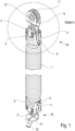
- a complete spring assembly is shown, which is formed from an outer tension spring 1, a middle tension spring 3 and an inner tension spring 2.
- end terminations 35 are arranged at both ends, which are the same in the end attachment of the spring assembly, namely with termination elements 4, 5, which are connected to one another on the outside by connecting elements 6.
- An end closure 35 with a rotatable roller 11 is shown at the upper end of the spring assembly outside of the closure elements 4 , 5 .
- the roller 11 has been shown arranged on an axle 12 and journaled in axle bearings 13 located in the upper section.
- a hook 31 is formed here with an end bend 32; other end formations are possible.
- FIG 2 is reproduced in an enlarged detail view A of the upper end of the spring assembly.
- the interaction of the end elements 4 , 5 with connecting elements 6 to be inserted in openings 16 can be seen in particular from this illustration.
- the connecting elements 6 engage in a spread 19 of the outer tension spring 1 in its end area with its locks 25 .
- the terminating elements 4, 5 have connecting lugs 8 on the upper side, over which a curved hook 31 or the end termination 35 can be formed.
- FIG. 7 In a single representation according to figure 7 the design of a closing element 4, 5 is given in a perspective view.
- the connecting straps 8 contain bores 9 which connect the two closing elements 4, 5 with one another in a non-positive and positive manner after assembly in the upper outer area using suitable connecting means.
- An opening 33 is worked into the connecting lug 8, from the bent material of which an upper holder 10 is formed, which is used for fastening the inner tension spring 2 at the end.
- the inner tension spring 2 has a constriction 22 for this purpose.
- the figure 3 shows the overall design of the spring assembly in a rotated representation compared to the figure 1 .
- a cut BB is in the figure 4 only one of the connection areas of the tension spring package is shown.
- the virtual embracing of the terminating elements 4, 5, but with only one of the terminating elements 4 or 5, is visible, with the constriction 22 at the upper end 34 of the inner tension spring 2 enclosing this by embracing the upper two holders 10 of the terminating elements 4 , 5 has assumed a fastening position.
- the middle tension spring 3 lying around the inner tension spring 2 is visible in the end area of the spread 21 .
- the central tension spring 3 receives its holding position via the lower brackets 14 of the two end elements 4, 5.
- the outer tension spring 1 is held by the closing elements 4, 5 and in connection with the connecting elements 6 engaging in the openings 16. Through the engagement of the locks 25 of the connecting element 6 in the spread 19 of the end area of the outer tension spring 1, the outer tension spring 1 is held in place and at the same time the closing elements 4, 5 are held together in the lower area.
- the terminating elements 4, 5 are placed around a reduction in an outer diameter 20, thereby protruding terminating parts are avoided, which enables better assembly of the spring assembly even in narrow building gaps or the like.
- the connecting element 6 is in the figure 8 reproduced in a single representation.
- the connecting element 6 has a back 7 which is formed in the upper part in a connecting manner between the two cantilevered and angled locks 25 .
- the back 7 has an opening 24 on the underside, which is connected on the outside by legs 29 and an inwardly bent bend 23 .
- the two barriers 25 which are spaced apart from one another, have on the upper side a substantially straight section 26 or a section 26 that rises slightly outwards, which at the end merges into a bevel 27 that falls in the direction of the back 7 .
- a hook 28 is formed at the end of the bevel 27 .
- the lock 25 penetrates between the spread 19 of the outer diameter of the outer tension spring 1 via the sections 26 and hooks by means of the hook 28 with a lower coil of the outer tension spring 1. At the same time, the bend 23 lies against the adjacent one spring coil on.
- end-side terminating elements 36, 43 Another preferred embodiment of the placement of end-side terminating elements 36, 43 give the figures 9 and 10 again.
- the terminating elements 36, 43 essentially correspond in structure to the terminating elements 4, 5. Modifications were carried out in the first bends from the straight base, in that the side lines have a shoulder 38. This shoulder 38 also serves to strengthen the positioning by the hooks 28 because a connecting element 39 used in this embodiment is provided with stops 41 which engage in the shoulders 38 .
- the connecting element 39 consists of a substantially straight base 42 from which laterally angled holding arms 40 extend, which lie around the ends of the end elements 36 and 43 on the outside.
- the projecting retaining arms 40 have a further bend with the stop 41 for close contact with the closing elements 36, 43.
- the hooks 28 are formed in the same design as in the connection element 6 .
Landscapes
- Engineering & Computer Science (AREA)
- General Engineering & Computer Science (AREA)
- Mechanical Engineering (AREA)
- Springs (AREA)
Applications Claiming Priority (1)
| Application Number | Priority Date | Filing Date | Title |
|---|---|---|---|
| DE102021117572.0A DE102021117572A1 (de) | 2021-07-07 | 2021-07-07 | Endabschluss für ein Federpaket |
Publications (1)
| Publication Number | Publication Date |
|---|---|
| EP4130509A1 true EP4130509A1 (fr) | 2023-02-08 |
Family
ID=82446518
Family Applications (1)
| Application Number | Title | Priority Date | Filing Date |
|---|---|---|---|
| EP22183348.6A Pending EP4130509A1 (fr) | 2021-07-07 | 2022-07-06 | Bord terminal pour un bloc-ressort |
Country Status (2)
| Country | Link |
|---|---|
| EP (1) | EP4130509A1 (fr) |
| DE (1) | DE102021117572A1 (fr) |
Citations (6)
| Publication number | Priority date | Publication date | Assignee | Title |
|---|---|---|---|---|
| US5692737A (en) | 1996-06-25 | 1997-12-02 | Perlsweig; Leon | Helical spring amusement device and stress reliever |
| DE202014100474U1 (de) * | 2013-02-05 | 2014-02-25 | Brandholding Kg | Federpaket mit mehreren, ineinander angeordneten Schraubenfedern und zwei Federendenaufnahmen |
| DE102012109477A1 (de) | 2012-10-05 | 2014-04-10 | Doco International B.V. | Zugfeder |
| DE202018107343U1 (de) | 2018-12-20 | 2019-01-14 | Alcomex Beheer Bv | Zugfederanordnung |
| DE202018107342U1 (de) | 2018-12-20 | 2019-01-14 | Alcomex Beheer Bv | Federpaket |
| DE202018107344U1 (de) * | 2018-12-20 | 2019-01-14 | Alcomex Beheer Bv | Zugfeder, sowie Federpaket mit einer inneren und äußeren Zugfeder |
Family Cites Families (1)
| Publication number | Priority date | Publication date | Assignee | Title |
|---|---|---|---|---|
| DE202018102225U1 (de) | 2018-04-20 | 2018-07-09 | Alcomex Beheer Bv | Anschlusselement für ein Zugfederelement, sowie Zugfederelement mit einem Anschlusselement |
-
2021
- 2021-07-07 DE DE102021117572.0A patent/DE102021117572A1/de active Pending
-
2022
- 2022-07-06 EP EP22183348.6A patent/EP4130509A1/fr active Pending
Patent Citations (6)
| Publication number | Priority date | Publication date | Assignee | Title |
|---|---|---|---|---|
| US5692737A (en) | 1996-06-25 | 1997-12-02 | Perlsweig; Leon | Helical spring amusement device and stress reliever |
| DE102012109477A1 (de) | 2012-10-05 | 2014-04-10 | Doco International B.V. | Zugfeder |
| DE202014100474U1 (de) * | 2013-02-05 | 2014-02-25 | Brandholding Kg | Federpaket mit mehreren, ineinander angeordneten Schraubenfedern und zwei Federendenaufnahmen |
| DE202018107343U1 (de) | 2018-12-20 | 2019-01-14 | Alcomex Beheer Bv | Zugfederanordnung |
| DE202018107342U1 (de) | 2018-12-20 | 2019-01-14 | Alcomex Beheer Bv | Federpaket |
| DE202018107344U1 (de) * | 2018-12-20 | 2019-01-14 | Alcomex Beheer Bv | Zugfeder, sowie Federpaket mit einer inneren und äußeren Zugfeder |
Also Published As
| Publication number | Publication date |
|---|---|
| DE102021117572A1 (de) | 2023-01-12 |
Similar Documents
| Publication | Publication Date | Title |
|---|---|---|
| DE3617911C2 (fr) | ||
| DE102008032964B4 (de) | Gassackanordnung für ein Fahrzeuginsassen-Rückhaltesystem | |
| DE102012209272A1 (de) | Befestigungsvorrichtung für Solarpaneele | |
| WO2007131557A1 (fr) | Rail de tension ou de guidage avec sécurité antiperte pour boulon de retenue | |
| DE202007015605U1 (de) | Verbindungsbeschlag und Montageanordnung | |
| DE202013007519U1 (de) | Montageplatte für Möbelstellantriebe | |
| DE102012209267A1 (de) | Montageanordnung | |
| DE4244395C2 (de) | Nutenstein zum Einsatz in eine Längsnut eines Profilstabes sowie Profilverbinder | |
| DE9317983U1 (de) | Element zum Befestigen an einer hinterschnittenen Öffnung | |
| DE2726683C2 (de) | In vorgegebenen Grenzen drehbewegliche Verankerung eines Umlenkbeschlages für einen Sicherheitsgurt | |
| DE2026331A1 (de) | Brillengestell | |
| EP0020943A1 (fr) | Pinces de suspension pour conducteurs et faisceaux de conducteurs isolés | |
| DE202018100613U1 (de) | Anordnung mit zwei über einen Anreihverbinder miteinander verbundenen Schaltschrankrahmengestellen | |
| DE102019114002B3 (de) | Bedieneinheit für ein Fahrzeug | |
| DE102010024419A1 (de) | Verfahren zur Befestigung von einem ersten Bauteil an einem zweiten Bauteil eines Fahrzeugs sowie entsprechende Befestigungsvorrichtung | |
| DE102021117572A1 (de) | Endabschluss für ein Federpaket | |
| DE10334050A1 (de) | Vorrichtung zur Befestigung eines Anschlussfittings an einem Gegenstand, insbesondere an einer Wand | |
| DE20004939U1 (de) | Zweiteiliges Scharnier mit außenliegender Scharnierachse und Montagehilfe | |
| DE4309210B4 (de) | Installationselement und Installationsprofil | |
| EP4019819A1 (fr) | Dispositif à deux composants, en particulier collier doté d'un anneau de collier | |
| DE102018107083A1 (de) | Befestigungseinrichtung und Verfahren zur Befestigung eines Anbauteils an einem Tragteil, Bauteilsystem und Kraftfahrzeug | |
| DE10133677A1 (de) | Rohrbefestigung | |
| CH626683A5 (en) | Hinge for a window or door | |
| DE202018102226U1 (de) | Endbefestigungsvorrichtung für ein Zugfederelement, sowie ein Zugfederelement mit einer Endbefestigungsvorrichtung | |
| DE29907394U1 (de) | Bandhälfte eines Bandes für Fenster, Türen o.dgl. |
Legal Events
| Date | Code | Title | Description |
|---|---|---|---|
| PUAI | Public reference made under article 153(3) epc to a published international application that has entered the european phase |
Free format text: ORIGINAL CODE: 0009012 |
|
| STAA | Information on the status of an ep patent application or granted ep patent |
Free format text: STATUS: THE APPLICATION HAS BEEN PUBLISHED |
|
| AK | Designated contracting states |
Kind code of ref document: A1 Designated state(s): AL AT BE BG CH CY CZ DE DK EE ES FI FR GB GR HR HU IE IS IT LI LT LU LV MC MK MT NL NO PL PT RO RS SE SI SK SM TR |
|
| STAA | Information on the status of an ep patent application or granted ep patent |
Free format text: STATUS: REQUEST FOR EXAMINATION WAS MADE |
|
| 17P | Request for examination filed |
Effective date: 20230804 |
|
| RBV | Designated contracting states (corrected) |
Designated state(s): AL AT BE BG CH CY CZ DE DK EE ES FI FR GB GR HR HU IE IS IT LI LT LU LV MC MK MT NL NO PL PT RO RS SE SI SK SM TR |