EP4130631B1 - Verfahren und steuergerät zum testen einer zweiphasigen kühlvorrichtung, computerprogramm und computerlesbares medium - Google Patents
Verfahren und steuergerät zum testen einer zweiphasigen kühlvorrichtung, computerprogramm und computerlesbares medium Download PDFInfo
- Publication number
- EP4130631B1 EP4130631B1 EP21189808.5A EP21189808A EP4130631B1 EP 4130631 B1 EP4130631 B1 EP 4130631B1 EP 21189808 A EP21189808 A EP 21189808A EP 4130631 B1 EP4130631 B1 EP 4130631B1
- Authority
- EP
- European Patent Office
- Prior art keywords
- temperature
- cooling device
- cooling medium
- cooling
- graph
- Prior art date
- Legal status (The legal status is an assumption and is not a legal conclusion. Google has not performed a legal analysis and makes no representation as to the accuracy of the status listed.)
- Active
Links
Images



Classifications
-
- F—MECHANICAL ENGINEERING; LIGHTING; HEATING; WEAPONS; BLASTING
- F28—HEAT EXCHANGE IN GENERAL
- F28D—HEAT-EXCHANGE APPARATUS, NOT PROVIDED FOR IN ANOTHER SUBCLASS, IN WHICH THE HEAT-EXCHANGE MEDIA DO NOT COME INTO DIRECT CONTACT
- F28D15/00—Heat-exchange apparatus with the intermediate heat-transfer medium in closed tubes passing into or through the conduit walls ; Heat-exchange apparatus employing intermediate heat-transfer medium or bodies
- F28D15/02—Heat-exchange apparatus with the intermediate heat-transfer medium in closed tubes passing into or through the conduit walls ; Heat-exchange apparatus employing intermediate heat-transfer medium or bodies in which the medium condenses and evaporates, e.g. heat pipes
- F28D15/06—Control arrangements therefor
-
- G—PHYSICS
- G01—MEASURING; TESTING
- G01M—TESTING STATIC OR DYNAMIC BALANCE OF MACHINES OR STRUCTURES; TESTING OF STRUCTURES OR APPARATUS, NOT OTHERWISE PROVIDED FOR
- G01M99/00—Subject matter not provided for in other groups of this subclass
- G01M99/002—Thermal testing
-
- F—MECHANICAL ENGINEERING; LIGHTING; HEATING; WEAPONS; BLASTING
- F28—HEAT EXCHANGE IN GENERAL
- F28D—HEAT-EXCHANGE APPARATUS, NOT PROVIDED FOR IN ANOTHER SUBCLASS, IN WHICH THE HEAT-EXCHANGE MEDIA DO NOT COME INTO DIRECT CONTACT
- F28D15/00—Heat-exchange apparatus with the intermediate heat-transfer medium in closed tubes passing into or through the conduit walls ; Heat-exchange apparatus employing intermediate heat-transfer medium or bodies
- F28D15/02—Heat-exchange apparatus with the intermediate heat-transfer medium in closed tubes passing into or through the conduit walls ; Heat-exchange apparatus employing intermediate heat-transfer medium or bodies in which the medium condenses and evaporates, e.g. heat pipes
- F28D15/0283—Means for filling or sealing heat pipes
-
- F—MECHANICAL ENGINEERING; LIGHTING; HEATING; WEAPONS; BLASTING
- F28—HEAT EXCHANGE IN GENERAL
- F28D—HEAT-EXCHANGE APPARATUS, NOT PROVIDED FOR IN ANOTHER SUBCLASS, IN WHICH THE HEAT-EXCHANGE MEDIA DO NOT COME INTO DIRECT CONTACT
- F28D20/00—Heat storage plants or apparatus in general; Regenerative heat-exchange apparatus not covered by groups F28D17/00 or F28D19/00
- F28D20/02—Heat storage plants or apparatus in general; Regenerative heat-exchange apparatus not covered by groups F28D17/00 or F28D19/00 using latent heat
- F28D20/021—Heat storage plants or apparatus in general; Regenerative heat-exchange apparatus not covered by groups F28D17/00 or F28D19/00 using latent heat the latent heat storage material and the heat-exchanging means being enclosed in one container
-
- F—MECHANICAL ENGINEERING; LIGHTING; HEATING; WEAPONS; BLASTING
- F28—HEAT EXCHANGE IN GENERAL
- F28F—DETAILS OF HEAT-EXCHANGE AND HEAT-TRANSFER APPARATUS, OF GENERAL APPLICATION
- F28F2200/00—Prediction; Simulation; Testing
-
- F—MECHANICAL ENGINEERING; LIGHTING; HEATING; WEAPONS; BLASTING
- F28—HEAT EXCHANGE IN GENERAL
- F28F—DETAILS OF HEAT-EXCHANGE AND HEAT-TRANSFER APPARATUS, OF GENERAL APPLICATION
- F28F2200/00—Prediction; Simulation; Testing
- F28F2200/005—Testing heat pipes
Definitions
- the invention relates to the field of two-phase cooling devices.
- the invention relates to a method and a controller for testing a two-phase cooling device, to a computer program for operating the controller, and to a computer-readable medium in which the computer program is stored.
- Advanced two-phase cooling devices e.g. 3D-cooling devices, like 2D vapor chambers, and/or 2D-cooling devices, like 2D heat pipes or thermosyphons, for power electronic applications are made from a material having a high thermal conductivity, e.g. from metal, e.g. copper, and rely on using a cooling medium, e.g. water, as a working fluid for its optimal thermal properties.
- a cooling medium e.g. water
- the cooling device 20 is symmetric with respect to a symmetry axis 34.
- the cooling device 20 is rotationally symmetric with respect to the symmetry axis 34.
- the cooling device 20 may be mirror-symmetric, wherein the symmetry axis 34 may be representative for a corresponding symmetry plane.
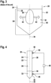
- the liquid cooling medium 36 begins to be surrounded by frozen cooling medium 40, in particular if the upper surface 38 of the liquid cooling medium 32 is closed, the pool of liquid cooling medium 36 is transformed into a pocket of enclosed liquid cooling medium 36 and high pressures on the inner walls 26 of the housing 22 appear, which ultimately cause a bulging of the housing 22 and/or a leakage of the cooling medium 32 in the bottom region 30, and as a consequence a loss of cooling performance.
- Fig. 3 shows the bottom region 30 of Fig. 2 , wherein the cooling medium 32 is frozen such that the pocket of liquid cooling medium 36 is enclosed by the frozen cooling medium 40.
- the pressure acting on the housing 22 because of the expansion of the frozen cooling medium 40 and the presence of the pocket of liquid cooling medium 32 completely within the frozen cooling medium of 40 is represented by two arrows illustrating the direction 42 of the corresponding expansion force.
- the bulging of the housing 22 may in turn cause the leakage, through which the liquid cooling medium 36 may leak outside of the housing 22, and/or a loss of contact with the electronic component to be cooled, because of a deformed outer wall of the housing 22. Both cases will result in a failure of the cooling device 20 and/or the electronic component to be cooled.
- the correct amount of liquid cooling medium 36 is a tradeoff between the cooling performance and the reliability of the cooling device 20.
- the cooling performance has its optimum with a specific predefined amount of water, wherein the reliability of the cooling device 20 drops, if the amount of liquid cooling medium 36 is more than may be accommodated by the porous structure.
- the manufactures of the cooling devices 20 tend to fill a little bit more cooling medium 32 into the cavity 24, as needed in order to be on the safe side regarding the cooling performance of the cooling device 20.
- the cooling device 20 is overfilled, the above disadvantages may arise. Therefore, it is important to find out whether the correct amount of liquid cooling medium 36 is within the cavity 24.
- thermal energy storage systems comprising battery assemblies containing phase change materials and a monitoring system therefor.
- thermal stores comprising battery assemblies having integral control means for management of the thermal energy provided by the battery assembly are described.
- an objective of the present invention is achieved by a method for testing a two-phase cooling device.
- the cooling device has a housing surrounding a cavity and a cooling medium within the cavity.
- the method comprises: controlling a temperature of ambient air of the cooling device such that the cooling medium within the cavity transitions from its liquid state to its solid state and/or from its solid state to its liquid state, while monitoring a first temperature of the cooling device over a predetermined amount of time; determining whether the monitored first temperature fulfills a predetermined criterion; and determining that the cooling device is overfilled with the cooling medium if the criterion is fulfilled.
- the cooling device if the cooling device is overfilled, the pool of liquid cooling medium is formed in the bottom region. If the cooling device is cooled down to a freezing temperature of the cooling medium or below, the enclosed pocket of liquid cooling medium is formed within the frozen cooling medium. The pool as well as the pocket of liquid cooling medium result in that the cooling device has a much larger latent heat within the bottom region than in the top region. This effect can accurately be seen from the monitored first temperature at the phase transitions. In addition, measuring and monitoring the first temperature may be carried out in an easy way. Further, the method may be carried out without the need to open the cooling device and/or to measure the amount of cooling medium within the cooling device, e.g. by removing the cooling medium and measuring its volume.
- the above method for testing the two-phase cooling device in particular for testing whether the cooling device is overfilled or not, may be carried out easily, may be carried out without the need to open the cooling device and/or to measure the amount of cooling medium within the cooling device, e.g. by removing the cooling medium and measuring its volume, and/or is very accurate.
- the two-phase cooling device may be a 3D-cooling device, like a 3D vapor chamber, and/or a 2D-cooling device, like a 2D heat pipe or thermosyphon.
- the housing may comprise or may be made of a metal having a high thermal conductivity, e.g. copper.
- the cooling medium may for example be water.
- the predetermined criterion may be a predetermined temperature pattern over time.
- the first temperature of the cooling device may be monitored by receiving a signal from a first sensor, which may be arranged at the outside of the housing in thermal contact with the housing, which may be thermally isolated against the ambient air, and which may be arranged at the bottom region.
- a neuronal network may be trained and used to differentiate temperature patterns of cooling devices, which are overfilled, from temperature patterns of cooling devices, which are not overfilled.
- the training may be carried out with the help of a training set of temperature patterns of correspondingly overfilled and properly filled cooling devices.
- the monitored first temperature fulfills the at least one predetermined criterion by determining at least one graph, which represents the monitored first temperature over the time, during which the first temperature is monitored, and determining whether the graph fulfills the predetermined criterion. For example, if the first temperature is measured for a give duration, e.g. during at least one of the phase transitions, the first temperature may not be measured continuously but at regular time intervals, e.g. at time intervals of a view seconds, e.g. every 6 or 8 seconds. Then, a trendline or average line may be determined from the measured temperature values, wherein the graph may correspond to the determined trendline or, respectively, average line.
- the graph enables in an easy way to see the temperature behaviour of the cooling device on the first side. Further, the graph enables an easy mathematical analysis of the temperature behaviour of the cooling device.
- the graph may be composed of a plurality of temperature measurements at consecutive time points.
- the graph fulfills the predetermined criterion by determining a first derivative of the graph; and determining an amount of extreme values of the derivate of the graph during one of the phase transitions and/or within the third section; wherein the predetermined criterion is fulfilled, if the derivate of the signal has at least two extreme values.
- the positions of the extreme values of the derivative correspond to the positions of turning points of the original graph.
- the extreme values each may be a local maximum or a local minimum of the derivative, and/or may be referred to as "peak".
- the cooling medium is absorbed within the porous structure having a relatively even thickness and porosity.
- the phase transition continues in the bottom region of the cooling device.
- overfilled cooling devices have a tendency to go along with a long phase transitions, during freezing as well as during melting.
- the duration of the phase transition is reflected in the width of the graph showing the phase transition. So, determining the width of the graph during at least one of the phase transitions of the cooling medium and/or within the third section, and determining that the predetermined criterion is fulfilled, if the determined width is larger than a predetermined width threshold, contributes to accurately and easily determining whether the cooling device is overfilled or not.
- the cooling device has a much larger latent heat within the bottom region than in the top region. Therefore, with an overfilled cooling device, the difference between the first temperature and the second temperature is quite big. So, it may be determined that the cooling device is overfilled, if the difference is larger than the predetermined difference threshold.
- the cooling device is overfilled or not by counting the amount of extreme values of the first derivative or by analysing the width of the graph, it is advantageous, if the first temperature is only monitored for one of the phase transitions or if the first temperature is monitored all over the test but only those values are analysed which are monitored during one of the phase transitions. If it is determined whether the cooling device is overfilled or not by counting the amount of extreme values of the first derivative, the criterion of having at least two extreme values refers to one of the phase transitions only. In other words, when analysing the first derivative of the graph during both phase transitions the corresponding derivative must have at least four extreme values in order to being able to classify the cooling device is being overfilled.
- the method further comprises arranging the cooling device in a temperature chamber, which encloses the ambient air and which enables the control of the temperature of the ambient air, prior to controlling the temperature of the ambient air.
- the method further comprises arranging the first sensor at the housing such that the first sensor has the thermal contact to the housing and is thermally isolated against the ambient air, prior to controlling the temperature of the ambient air.
- the first sensor is arranged at a bottom region of the housing.
- the effects of the overfilling of the cooling device may be seen at best within the bottom region, because of the formation of the pocket and the pool. Therefore, the effects on the first temperature are the strongest within the bottom region. Therefore, arranging the first sensor at the bottom region and correspondingly sensing the first temperature in the bottom region may contribute to a very easy and accurate determination of whether the cooling device is overfilled or not.
- the above features, advantages and/or effects of the method for testing the two-phase cooling device may be transferred to the controller for testing the two-phase cooling device, the computer program for operating the controller, and/or to the computer-readable medium on which the computer program is stored, as explained in the following. Therefore, a repetition of these features, advantages and/or effects is omitted and it is referred to the above explanations only in order to provide a concise description.
- the controller for testing the two-phase cooling device.
- the controller comprises a processor and a memory.
- the processor is configured to carry out the above method.
- An objective of the present invention is achieved by the computer program for operating the controller, which, when being executed by a processor, is adapted for performing the above method.
- An objective of the present invention is achieved by the computer-readable medium on which the above computer program is stored.
- the formation of the pocket of liquid cooling medium 36 and the associated bulging of the housing 22 and in case the leakage of the housing 22 may be avoided, if only those cooling devices 20 are used for applications at or below the freezing temperature of the cooling medium 32, which are not overfilled and/or in which the whole liquid cooling medium 36 may be absorbed by the porous structure.
- a very small amount of excess cooling medium i.e. more liquid cooling medium 36 than may be absorbed by the porous structure, may be tolerable.
- the corresponding cooling device 20 may be classified as not being overfilled, because such a very small amount of excess cooling medium does not harm the cooling device 20, if the cooling medium 32 freezes, because of the elasticity of the material of the housing 22 of the cooling device 20.
- the inventors of the present invention have recognized that a temperature behaviour of the cooling device 20 during a phase transition of the cooling medium 32 from its liquid state to its frozen state or vice versa may be representative for whether the cooling device 20 is overfilled or not.
- a first sensor 44 for measuring a first temperature of the cooling device 20 may be arranged at an outer circumference of the housing 22.
- the first sensor 44 may be arranged at the housing 22 in the bottom region 30.
- the first sensor 44 may be in thermal and/or direct contact with the housing 22.
- the first sensor 44 may be fixed to the housing 22 by a thin layer of a thermally conductive glue.
- the first sensor 44 may be thermally isolated against the ambient air by a first insulation 46.
- a second sensor 50 for measuring a second temperature of the cooling device 20 may be arranged at an outer circumference of the housing 22.
- the second sensor 44 may be arranged at the housing 22 above the first sensor 44, e.g. in the top region 28.
- the second sensor 50 may be in thermal and/or direct contact with the housing 22.
- the second sensor 50 may be fixed to the housing 22 by a thin layer of a thermally conductive glue.
- the second sensor 50 may be thermally isolated against the ambient air by a second insulation 52.
- the first and in case the second sensor 44, 50 may be electrically coupled to a controller 48.
- the controller 48 may be arranged for receiving a first signal from the first sensor 44 and in case a second signal of the second sensor 50.
- the first signal may be representative for the first temperature.
- the second signal may be representative for a second temperature.
- the controller 48 may be configured to monitor the first and/or second temperature over the predetermined amount of time, e.g. during the whole test, during a transition of the cooling medium from its liquid state to its solid state and afterwards from its solid state to its liquid state, or during one of these phase transitions only. Further, the controller 48 may be configured to analyse the monitored first and/or second temperature regarding whether the cooling device 20 is overfilled or not.
- the controller 48 may be configured to carry out a method for testing the cooling device 20, in particular regarding whether the cooling device 20 is overfilled or not. Furthermore, the controller 48 may be configured to control the temperature of the ambient air in the temperature chamber.
- the controller 48 may comprise a processor and a memory.
- the controller 48 may be regarded as and/or may be coupled to a computer. If the controller 48 is coupled to a computer, one or more of the above tasks of the controller 48 may be outsourced to the computer.
- Fig. 5 shows a first diagram comprising several graphs, which represent temperatures of the cooling devices 20 of the same type, which have different amounts of cooling medium 32, during freezing and melting of the corresponding cooling medium 32.
- the cooling devices 20 may correspond to the above cooling device 20.
- the cooling devices 20 are arranged in the above temperature chamber, in which the temperature of the ambient air may be controlled.
- the temperatures of the ambient air and of the cooling devices 20 are represented by corresponding graphs within the first diagram. According to figure 5 , the temperature of the ambient air drops from 10°C to -10°C within the first five minutes. All other graphs, representing the temperatures of the cooling devices 20, roughly show a similar behaviour. In particular, all temperatures except for the temperature of the ambient air drop down to -4°C to -8°C in first sections of the corresponding graphs. This behaviour may be called supercooling effect and takes place before the cooling medium 32 starts freezing. The amount of supercooling does not correlate with the amount of the cooling medium 32 within the cooling devices 20 and may slightly vary for different test cycles.
- the temperatures start going down again in a third section.
- freezing is complete in the vicinity of the first sensor 44 but not yet complete in the bottom region 30, where there is the pool of liquid cooling medium 36.
- the housing 22, which normally has a high thermal conductivity and/or which for example may be made from copper, provides a thermal link between the firs sensor 44 and the freezing liquid cooling medium 36 at the bottom. That is why the temperature measured by the first sensor 44 never reaches the ambient temperature as long as some cooling medium 32 is in its liquid state at the bottom.
- the freezing is completed everywhere within the cavity 24, and there is no more liquid cooling medium 36 in the cavity 24, signalling the completion of freezing.
- the curves of temperatures within this third section strongly vary depending on the amount of cooling medium 32 within the cooling devices 20, if the cooling devices 20 are overfilled. Therefore, this third section may be used for determining whether the cooling devices 20 are overfilled or not, as explained below.
- the melting of the cooling medium 32 starts and the temperatures stay around 0°C for about 5 to 10 minutes, corresponding to the second section of the cooling process.
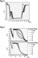
- Fig. 6 shows a second and a third diagram each comprising several graphs, which represent temperatures of the same cooling devices 20 having different amounts of cooling medium 32 during freezing of the cooling medium.
- the second diagram shown in figure 6 above the third diagram is a detailed view of the temperature graphs of an overfilled cooling device 20, i.e. a first cooling device S1, shown in figure 5 .
- the third diagram is a detailed view of the temperature graphs of a properly filled cooling device 20, i.e. a second cooling device S2, shown in figure 5 .
- These detailed views refer to the cooling process only.
- the detailed views of the melting process are shown in figure 7 .
- the second as well as the third diagram show graphs of an ambient temperature T_amb within the temperature chamber, an internal temperature T_in within the corresponding cooling device 20, and first, second, third, and fourth temperatures T1, T2, T3, T4 measured with sensors at the housing 22 of the corresponding cooling device 20.
- the first temperature T1 and the second temperature T2 may be sensed by the corresponding first sensors 44 and, respectively, the corresponding second sensors 50.
- the third and the fourth temperature T3, T4 may be sensed with corresponding further sensors (not shown) attached at the housings 22 in the top regions 28 with increasing distance to the corresponding bottom regions 30.
- the ambient temperature T_amb drops to -10°C within the first five minutes. All other temperatures T_in, T1, T2, T3, T4 drop down to -4°C to - 8°C in first sections of both diagrams due to the above supercooling effect.
- the freezing of the cooling medium 32 starts and the temperatures T_in, T1, T2, T3, T4 simultaneously jump up to 0°C.
- This jump is followed by the second sections of the graphs, which represents the period of evenly freezing of the cooling medium 32 and during which the temperatures remain close to 0°C.
- the second diagram representing the temperatures of the overfilled cooling device 20
- the duration of the second section varies depending on position of the corresponding sensor 44, 50 at the housing 22. This is because the cooling medium 32 finishes freezing first within the top region 28 of the cooling devices 20, in which the cooling medium is evenly distributed within the porous structure. In contrast, within the bottom region 28, where the additional cooling medium 32 is accumulated, e.g. with the pool, the freezing finishes last.
- the temperatures T_in, T1, T2, T3, T4 drop down again, there is a significant difference between the properly filled cooling device 20 represented by the third diagram and the overfilled cooling device 20 represented by the second diagram.
- the temperatures T_in, T1, T2, T3, T4 drop down quite evenly.
- the first to fourth temperatures T1, T2, T3, T4 measured at the housing 22 of the corresponding cooling device 20 drop down unevenly, wherein the corresponding graphs show at least two turning points.
- the liquid cooling medium 32 is basically absorbed within the porous structure having a relatively even thickness and porosity. Therefore, a latent heat density along the cooling device 20 is relatively constant.
- the heat flux is relatively evenly distributed across an outer surface of the cooling device 20. Therefore, the freezing of the liquid cooling medium 36 or the melting of the frozen cooling medium 40 (explained with respect to figure 8 ) within the porous structure begins and ends approximately simultaneously.
- liquid cooling medium 36 within the vertically oriented overfilled cooling device 20 forms the pool or the pocket of liquid cooling medium 36 within the bottom region 30.
- the cooling device 20 has a much larger latent heat within the bottom region 30 compared to the top region 28 of the same cooling device 20.
- the cooling or heating across 0°C even if the phase transition is already completed for cooling medium 32 within the porous structure, the freezing/melting continues within the bottom region 30 of the cooling device 20. Therefore and due to high thermal conductivity of the walls and the porous structure of the cooling device 20, the temperature of the wall cannot change freely until the pool and/or the pocket within the bottom region 30 is completely frozen or, respectively, melted.
- a width threshold may be determined in advance such that it may be determined that the cooling device 20 is overfilled, if the width of at least one of its temperature graphs within the third section is larger than the predetermined width threshold.
- a difference threshold may be determined in advance such that it may be determined that the cooling device 20 is overfilled, if a difference between the temperatures measured in the top region 28, e.g.
- the fourth temperature T4 and the temperatures measured in the bottom region 30, e.g. the first temperature T1, within the third section is larger than the predetermined difference threshold.
- the amount of turning points of at least one of the temperature graphs corresponding to the temperature in the bottom region 30, e.g. the first temperature T1 may be determined and it may be determined that the cooling device 20 is overfilled, if there are two or more turning points of the corresponding temperature graph within the third section.
- the turning points may be determined directly or may be derived from the first derivative of the corresponding temperature graph, wherein the positions of local extreme values of the derivative correspond to the positions of the turning points of the original graph.
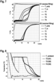
- Fig. 7 shows a fourth and a fifth diagram each comprising several graphs, which represent temperatures of the same cooling device 20 having different amounts of cooling medium 32 during melting of the cooling medium 32.
- the fourth diagram shown in figure 7 above the fifth diagram is a detailed view of the temperature graphs of the overfilled cooling device 20 shown in figure 5 .
- the fifth diagram is a detailed view of the temperature graphs of the properly filled cooling device 20 shown in figure 5 .
- These detailed views refer to the melting process only.
- the detailed views of the freezing process are shown above in figure 6 .
- the different sections of the graphs during the melting process widely correspond to the inverse freezing process.
- the graphs of the first to fourth temperatures T1, T2, T3, T4 show the same uneven behaviour in the section corresponding to the third section, i.e.
- cooling device 20 may be determined whether the cooling device 20 is overfilled or not by analysing the temperatures, in particular the graphs representing the temperatures, during the melting process, in accordance with the above determination during the freezing process.
- a width threshold may be determined in advance such that it may be determined that the cooling device 20 is overfilled, if the width of at least one of its temperature graphs within the corresponding melting section is larger than the predetermined width threshold.
- a difference threshold may be determined in advance such that it may be determined that the cooling device 20 is overfilled, if a difference between the temperatures measured in the top region 28, e.g.
- the fourth temperature T4 and the temperatures measured in the bottom region 30 within the corresponding melting section is larger than the predetermined difference threshold.
- the amount of turning points of at least one of the temperature graphs corresponding to the temperature in the bottom region 30, e.g. the first temperature T1 may be determined and it may be determined that the cooling device 20 is overfilled, if there are two or more turning points of the corresponding temperature graph within the corresponding melting section.
- the turning points may be determined directly or may be derived from the first derivative of the corresponding temperature graph, wherein the positions of local extreme values of the derivative correspond to the positions of the turning points of the original graph.
- Fig. 8 shows a sixth diagram comprising several graphs, which represent temperatures of different cooling devices 20 having different amounts of cooling medium 32 during freezing.
- the first cooling device S1 is overfilled
- the second cooling device S2 has the proper amount of cooling medium 32
- a third cooling device S3 has an amount of cooling medium 32 as provided from the manufacturer of the cooling devices 20.
- the cooling devices S1, S2, S3 correspond to the cooling device 20 and only differ from each other by the contained amount of cooling medium 32.
- only the temperature graph of the overfilled first cooling device S1 shows the broad phase transition and the two turning points within the third section.
- Fig. 9 shows a seventh diagram comprising first derivatives of the graphs representative for the temperatures of the different cooling devices 20 according to figure 8 .
- the derivative of the graph of the overfilled first cooling device S1 shows the two extreme values, in this case local minima, within the third section.
- Fig. 10 shows an eighth diagram comprising several graphs, which represent temperatures of different cooling devices 20 having different amounts of cooling medium 32 during melting.
- the first to third cooling devices S1, S2, S3 correspond to the above first to third cooling devices S1, S2, S3.
- the temperature graph of the overfilled first cooling device S1 shows the broad phase transition and the two turning points within the third section.
- Fig. 11 shows a nineth diagram comprising first derivatives of the graphs representative for the temperatures of the different cooling devices 20 according to figure 10 .
- the derivative of the graph of the overfilled first cooling device S1 shows the two extreme values, in this case local maxima, within the third section.
- the first to fourth temperature graphs T1, T2, T3, T4 and their derivatives shown in figures 5 to 11 correspond to different temperature patterns. These patterns vary depending on whether the corresponding cooling device 20 is overfilled or not and on the position of the housing 22 at which the corresponding temperature is measured. Therefore, all temperature graphs of overfilled cooling devices 20 with the corresponding temperature not being measured at the top or close to the top of the corresponding cooling device 20 show the same or at least a similar temperature pattern.
- a template of the temperature pattern may be determined in advanced and may be used for differentiating temperature patterns of overfilled cooling devices 20 from temperature patterns of properly filled cooling devices 20, e.g. by a neural network.
- the predetermined temperature pattern may comprise the width of the corresponding graph being larger than the above width threshold and/or the two or more turning points, each within the third section.
- Fig. 12 shows a flow chart of an exemplary embodiment of a method for testing a two-phase cooling device, according to the present invention, in particular for testing one of the above cooling devices 20, S1, S2, S3.
- the method may be used for testing whether the corresponding cooling device 20 is overfilled by the cooling medium 32 or not.
- an overfilling up to about 5% may be regarded as not being critical and/or as not being overfilled, because in these cases the pool and/or the pocket of liquid cooling medium 36, which is formed in the 5% overfilled cooling device 20, do not harm the cooling device 20 during freezing.
- the elasticity of the material of the housing 22 may allow a slight deformation caused by the pool and/or pocket of the housing such that the corresponding disadvantages and/or damages may not occur.
- the temperature sensors e.g. the first and second sensor 44, 50 are attached to the housing 22 of the cooling device 20 to be tested, e.g. as explained above with respect to figure 4 . If the test is carried out by analysing the width of the temperature graphs and/or the amount of turning points of the graphs or the extreme values of the corresponding derivates, the first sensor 44 is sufficient for carrying out the method. If the test is carried out by analysing the differences of the temperatures measured at different positions of the housing 22, the second sensor 50 is needed for carrying out the method.
- the cooling device 20 comprising the sensor(s) 44, 50 may be arranged in the temperature chamber.
- the cooling device 20 is arranged vertically, as it would be during normal usage and as it is shown with respect to figures 1 to 4 .
- the temperature of the ambient air e.g. the above ambient temperature T_amb
- the temperature of the ambient air may be controlled such that the cooling medium 32 within the cooling device 20 to be tested undergoes a phase transition from its liquid state to its solid state and afterwards from its solid state to its liquid state, from its liquid state to its solid state only, or from its solid state to its liquid state only.
- the method easily may be extended to monitoring and analysing both phase transitions, or only the phase transition from the solid state to the liquid state.
- the ambient temperature T_amb may be controlled such that it crosses 0°C, e.g. from 10°C to -10°C, e.g. by the controller 48.
- the temperature of the cooling device 20 may be monitored, e.g. the first temperature T1. Additionally, another temperature of the cooling device 20 may be monitored, e.g. the second, the third, and/or the fourth temperature T2, T3, T4. In particular, the temperature(s) may be monitored during the third section, which corresponds to the freezing section of the corresponding graph.
- the graph(s) representing the monitored temperature(s) may be determined.
- the graph representing the first temperature T1 may be determined.
- step A12 it is determined whether the monitored temperature fulfills the predetermined criterion.
- step A14 it is determined that the cooling device 20 under test is overfilled.
- step A16 it is determined that the cooling device 20 under test is not overfilled.
- Fig. 13 shows a flow chart of an exemplary embodiment of a method for determining whether the predetermined criterion is fulfilled, according to the present invention.
- the method of figure 13 may be implemented, e.g. as a subroutine, in the method explained with respect to figure 12 .
- the method of figure 13 may be carried out as the step A12 of the method of figure 12 .
- step A20 the derivative of the graph, which has been determined in step A10 of the method of figure 12 , may be determined, e.g. by a corresponding mathematical application.
- step A22 the amount of extreme values of the derivative is determined, e.g. within the duration of at least one of the phase transitions, e.g. within the third section.
- step A24 it is determined whether the amount of extreme values is 2 or more, in case the extreme values are determined for one phase transition only. If the amount of extreme values is 2 or more, the method proceeds in step A26. If the amount of extreme values is less than 2, the method proceeds in step A28. Alternatively, if both phase transitions are monitored, it is determined whether the amount of extreme values is 4 or more.
- step A26 it is determined that the predetermined criterion is fulfilled.
- step A28 it is determined that the predetermined criterion is not fulfilled.
- Fig. 14 shows a flow chart of an exemplary embodiment of a method for determining whether the predetermined criterion is fulfilled, according to the present invention.
- the method of figure 14 may be implemented, e.g. as a subroutine, in the method explained with respect to figure 12 .
- the method of figure 14 may be carried out as the step A12 of the method of figure 12 .
- step A30 the width of the graph, which has been determined in step A10 of the method of figure 12 , during at least one of the phase transitions, e.g. within the third section, is determined.
- step A32 it is determined whether the width of the graph is larger than the predetermined width threshold. If the width of the graph is larger than the predetermined width threshold, the method proceeds in step A34. If the width of the graph is not larger than the predetermined width threshold, the method proceeds in step A36.
- step A34 it is determined that the predetermined criterion is fulfilled.
- step A36 it is determined that the predetermined criterion is not fulfilled.
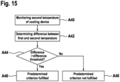
- Fig. 15 shows a flow chart of an exemplary embodiment of a method for determining whether the predetermined criterion is fulfilled, according to the present invention.
- the method of figure 15 may be implemented, e.g. as a subroutine, in the method explained with respect to figure 12 .
- the method of figure 15 may be carried out as the step A12 of the method of figure 12 .
- step A40 the second temperature T2, which has been sensed by the second sensor 50 in the top region 28, may be monitored.
- step A42 the difference between the monitored first and second temperature T1, T2 is determined, e.g. within the duration of at least one of the phase transitions, e.g. within the third section.
- step A44 it is determined whether the determined difference is larger than the predetermined difference threshold. If the determined difference is larger than the predetermined difference threshold, the method proceeds in step A46. If the determined difference is not larger than the predetermined difference threshold, the method proceeds in step A48.
- step A46 it is determined that the predetermined criterion is fulfilled.
- step A48 it is determined that the predetermined criterion is not fulfilled.
Landscapes
- Engineering & Computer Science (AREA)
- Physics & Mathematics (AREA)
- Thermal Sciences (AREA)
- Mechanical Engineering (AREA)
- General Engineering & Computer Science (AREA)
- Life Sciences & Earth Sciences (AREA)
- Sustainable Development (AREA)
- General Physics & Mathematics (AREA)
- Investigating Or Analyzing Materials Using Thermal Means (AREA)
Claims (12)
- Verfahren zum Prüfen einer Zweiphasenkühlvorrichtung (20), wobei die Kühlvorrichtung (20) ein Gehäuse (22) aufweist, das einen Hohlraum (24) und ein Kühlmedium (32) in dem Hohlraum (24) umgibt, wobei das Verfahren Folgendes umfasst:Steuern einer Temperatur von Umgebungsluft der Kühlvorrichtung (20) derart, dass das Kühlmedium (32) in dem Hohlraum (24) von seinem flüssigen Zustand in seinen festen Zustand und/oder von seinem festen Zustand in seinen flüssigen Zustand übergeht, während eines Überwachens der ersten Temperatur (T1) der Kühlvorrichtung (20) über eine vorbestimmte Zeitdauer;Bestimmen, ob die überwachte erste Temperatur (T1) ein vorbestimmtes Kriterium erfüllt; undBestimmen, dass die Kühlvorrichtung (20) mit dem Kühlmedium (32) überfüllt ist, wenn das vorbestimmte Kriterium erfüllt wird.
- Verfahren nach Anspruch 1, wobei durch Folgendes bestimmt wird, ob die überwachte erste Temperatur (T1) das mindestens eine vorbestimmte Kriterium erfüllt,Bestimmen mindestens einer Kurve, die die überwachte erste Temperatur (T1) über die Zeit darstellt, während derer die erste Temperatur (T1) überwacht wird, undBestimmen, ob die Kurve das vorbestimmte Kriterium erfüllt.
- Verfahren nach Anspruch 2, wobeidie Kurve der überwachten ersten Temperatur (T1) einen ersten Abschnitt mit fallender Temperatur umfasst, der eine Unterkühlung des Kühlmediums (32) in seinem flüssigen Zustand in der Kühlvorrichtung (20) anzeigt, wobei die Kurve danach einen Sprung auf eine Gefriertemperatur des Kühlmediums (32) umfasst, der den Beginn eines Einfrierens des Kühlmediums (32) anzeigt,wobei danach die Kurve einen zweiten Abschnitt bei der Gefriertemperatur des Kühlmediums (32) umfasst, der das Einfrieren des Kühlmediums (32) anzeigt, und wobei danach die Kurve einen dritten Abschnitt mit fallender Temperatur umfasst; wobei das vorbestimmte Kriterium in dem dritten Abschnitt gesucht wird.
- Verfahren nach einem der Ansprüche 2 oder 3, wobei durch Folgendes bestimmt wird, ob die Kurve das vorbestimmte Kriterium erfüllt,Bestimmen einer ersten Ableitung der Kurve; und Bestimmen einer Anzahl an Extremwerten der Ableitung der Kurve während eines der Phasenübergänge und/oder in dem dritten Abschnitt;wobei das vorbestimmte Kriterium erfüllt wird, wenn die Ableitung des Signals mindestens zwei Extremwerte aufweist.
- Verfahren nach einem der Ansprüche 2 oder 3, wobei durch Bestimmen einer Breite der Kurve während mindestens eines der Phasenübergänge des Kühlmediums (32) und/oder in dem dritten Abschnitt bestimmt wird, ob die Kurve das vorbestimmte Kriterium erfüllt; wobei das vorbestimmte Kriterium erfüllt wird, wenn die bestimmte Breite größer als ein vorbestimmter Breitenschwellenwert ist.
- Verfahren nach Anspruch 1, wobei die erste Temperatur (T1) an einem unteren Bereich (30) des Gehäuses (22) erfasst wird, wobei das Verfahren ferner Folgendes umfasst:Überwachen einer zweiten Temperatur (T2) der Kühlvorrichtung (20), wobei die zweite Temperatur (T2) in einem oberen Bereich (28) des Gehäuses (22) erfasst wird, während die erste Temperatur (T1) überwacht wird; undBestimmen einer Differenz zwischen der überwachten ersten und zweiten Temperatur (T1, T2) während mindestens eines der Phasenübergänge des Kühlmediums (32);wobei das vorbestimmte Kriterium erfüllt wird, wenn die bestimmte Differenz größer als ein vorbestimmter Differenzschwellenwert ist.
- Verfahren nach einem der vorhergehenden Ansprüche, ferner umfassend:
Anordnen der Kühlvorrichtung (20) in einer Temperaturkammer, die die Umgebungsluft umschließt und die die Steuerung der Temperatur der Umgebungsluft ermöglicht, bevor die Temperatur der Umgebungsluft gesteuert wird. - Verfahren nach einem der vorhergehenden Ansprüche, ferner umfassend:
Anordnen des ersten Sensors (44) an dem Gehäuse (22) derart, dass der erste Sensor (44) den thermischen Kontakt mit dem Gehäuse (22) aufweist und thermisch von der Umgebungsluft isoliert ist, bevor die Temperatur der Umgebungsluft gesteuert wird. - Verfahren nach Anspruch 8,
wobei der erste Sensor (44) an einem unteren Bereich (30) des Gehäuses (22) angeordnet ist. - Steuerung (48) zum Prüfen einer Zweiphasenkühlvorrichtung (20), wobei die Steuerung (48) einen Prozessor und einen Speicher umfasst, wobei der Prozessor dazu ausgelegt ist, das Verfahren nach einem der Ansprüche 1 bis 6 auszuführen.
- Computerprogramm zum Betreiben einer Steuerung (48) zum Prüfen einer Zweiphasenkühlvorrichtung (20), das, wenn es von einem Prozessor ausgeführt wird, dazu eingerichtet ist, das Verfahren nach einem der Ansprüche 1 bis 6 durchzuführen.
- Computerlesbares Medium, in dem ein Computerprogramm nach Anspruch 11 gespeichert ist.
Priority Applications (4)
| Application Number | Priority Date | Filing Date | Title |
|---|---|---|---|
| EP21189808.5A EP4130631B1 (de) | 2021-08-05 | 2021-08-05 | Verfahren und steuergerät zum testen einer zweiphasigen kühlvorrichtung, computerprogramm und computerlesbares medium |
| US18/292,197 US20240353293A1 (en) | 2021-08-05 | 2022-06-08 | Method and controller for testing a two-phase cooling device, computer program, and computer-readable medium |
| PCT/EP2022/065444 WO2023011780A1 (en) | 2021-08-05 | 2022-06-08 | Method and controller for testing a two-phase cooling device, computer program, and computer-readable medium |
| CN202280048255.8A CN117716197A (zh) | 2021-08-05 | 2022-06-08 | 用于测试两相冷却设备的方法和控制器、计算机程序和计算机可读介质 |
Applications Claiming Priority (1)
| Application Number | Priority Date | Filing Date | Title |
|---|---|---|---|
| EP21189808.5A EP4130631B1 (de) | 2021-08-05 | 2021-08-05 | Verfahren und steuergerät zum testen einer zweiphasigen kühlvorrichtung, computerprogramm und computerlesbares medium |
Publications (3)
| Publication Number | Publication Date |
|---|---|
| EP4130631A1 EP4130631A1 (de) | 2023-02-08 |
| EP4130631B1 true EP4130631B1 (de) | 2024-10-02 |
| EP4130631C0 EP4130631C0 (de) | 2024-10-02 |
Family
ID=77226663
Family Applications (1)
| Application Number | Title | Priority Date | Filing Date |
|---|---|---|---|
| EP21189808.5A Active EP4130631B1 (de) | 2021-08-05 | 2021-08-05 | Verfahren und steuergerät zum testen einer zweiphasigen kühlvorrichtung, computerprogramm und computerlesbares medium |
Country Status (4)
| Country | Link |
|---|---|
| US (1) | US20240353293A1 (de) |
| EP (1) | EP4130631B1 (de) |
| CN (1) | CN117716197A (de) |
| WO (1) | WO2023011780A1 (de) |
Family Cites Families (13)
| Publication number | Priority date | Publication date | Assignee | Title |
|---|---|---|---|---|
| US6866092B1 (en) * | 1981-02-19 | 2005-03-15 | Stephen Molivadas | Two-phase heat-transfer systems |
| US5579828A (en) * | 1996-01-16 | 1996-12-03 | Hudson Products Corporation | Flexible insert for heat pipe freeze protection |
| US6119729A (en) * | 1998-09-14 | 2000-09-19 | Arise Technologies Corporation | Freeze protection apparatus for fluid transport passages |
| WO2002012814A1 (de) * | 2000-08-03 | 2002-02-14 | Globe Thermal Energy Ag | Latentwärmespeicher |
| EP2584876A1 (de) * | 2011-10-21 | 2013-04-24 | Thales Nederland B.V. | System zum schnellen und genauen Auffüllen einer Vorrichtung zur zweiphasigen Kühlung, insbesondere eines Wärmerohrs, das zur Verwendung in einem automatischen Verfahren angepasst ist |
| JP5771168B2 (ja) * | 2012-08-28 | 2015-08-26 | 株式会社東芝 | 蓄熱装置、空調装置及び蓄熱方法 |
| GB201309757D0 (en) * | 2013-05-31 | 2013-07-17 | Sunamp Ltd | Heat battery assemblies and monitoring system therefor |
| US20160109156A1 (en) * | 2014-10-21 | 2016-04-21 | A. O. Smith Corporation | Internal condenser for heat pump water heater |
| EP2974635A1 (de) * | 2015-02-02 | 2016-01-20 | Kuhn Rikon AG | Fehlererkennung bei einem Schnellkochtopf |
| CN106226633B (zh) * | 2016-09-09 | 2020-01-03 | 中国电力科学研究院 | 热管式绝缘套管试验装置 |
| AT518791B1 (de) * | 2016-12-14 | 2018-01-15 | Ait Austrian Inst Tech Gmbh | Verfahren zum bestimmen eines ladezustandes eines latentwärmespeichers |
| DE102017200524A1 (de) * | 2017-01-13 | 2018-07-19 | Siemens Aktiengesellschaft | Kühlvorrichtung mit einem Wärmerohr und einem Latentwärmespeicher, Verfahren zum Herstellen derselben und elektronische Schaltung |
| US11191190B2 (en) * | 2020-03-31 | 2021-11-30 | GM Cruise Holdings, LLC | Two-phase cooling systems for autonomous driving super computers |
-
2021
- 2021-08-05 EP EP21189808.5A patent/EP4130631B1/de active Active
-
2022
- 2022-06-08 CN CN202280048255.8A patent/CN117716197A/zh active Pending
- 2022-06-08 US US18/292,197 patent/US20240353293A1/en active Pending
- 2022-06-08 WO PCT/EP2022/065444 patent/WO2023011780A1/en not_active Ceased
Also Published As
| Publication number | Publication date |
|---|---|
| US20240353293A1 (en) | 2024-10-24 |
| EP4130631A1 (de) | 2023-02-08 |
| WO2023011780A1 (en) | 2023-02-09 |
| EP4130631C0 (de) | 2024-10-02 |
| CN117716197A (zh) | 2024-03-15 |
Similar Documents
| Publication | Publication Date | Title |
|---|---|---|
| Li et al. | Examining temporal and spatial variations of internal temperature in large-format laminated battery with embedded thermocouples | |
| US20220359946A1 (en) | Battery module gas sensor for battery cell monitoring | |
| Gulsoy et al. | In-situ temperature monitoring of a lithium-ion battery using an embedded thermocouple for smart battery applications | |
| Anthony et al. | Non-invasive measurement of internal temperature of a cylindrical Li-ion cell during high-rate discharge | |
| US9209494B2 (en) | Monitoring/managing electrochemical energy device using detected intercalation stage changes | |
| US9583796B2 (en) | Method for monitoring/managing electrochemical energy device by detecting intercalation stage changes | |
| Li et al. | A smart Li-ion battery with self-sensing capabilities for enhanced life and safety | |
| US9377341B1 (en) | Electronic liquid level sensing device and gauge for liquid-immersed power transformers, reactors and similar equipment | |
| Anthony et al. | Improved thermal performance of a Li-ion cell through heat pipe insertion | |
| US8641271B2 (en) | Method for testing heat pipes | |
| EP4130631B1 (de) | Verfahren und steuergerät zum testen einer zweiphasigen kühlvorrichtung, computerprogramm und computerlesbares medium | |
| US20230152259A1 (en) | Calorimeter for in operando measuring of the overall heat released by a battery cell | |
| CN110534831B (zh) | 电池内部温度测量方法 | |
| US20240288316A1 (en) | Apparatus and method for non-invasively sensing internal temperature of a fluid contained in a housing | |
| US9672303B2 (en) | System and method of predicting initial cooling of superconducting magnet | |
| JP2009281910A (ja) | 熱物性測定装置 | |
| Sologubenko et al. | Wall damage of cylindrical heat pipes caused by water freezing | |
| JP4175388B2 (ja) | 蓄熱装置及びエンジン | |
| KR101306422B1 (ko) | 오일 레벨 감지장치 | |
| US8739620B1 (en) | Liquid-sensing probe and methods for using the same | |
| JP7728965B2 (ja) | 電気化学デバイスの健全状態の推定 | |
| Egea et al. | Advanced electrothermal model validated by internal temperature measurements in cylindrical lithium-ion batteries | |
| CN115062468B (zh) | 一种电池包故障检测方法、装置、设备及介质 | |
| Alujjage et al. | Unraveling the Thermo-Electrochemical Behavior of Lithium-Ion Batteries Under Operational Extremes | |
| Wang | In-situ temperature sensing of lithium-ion cells under different conditions |
Legal Events
| Date | Code | Title | Description |
|---|---|---|---|
| PUAI | Public reference made under article 153(3) epc to a published international application that has entered the european phase |
Free format text: ORIGINAL CODE: 0009012 |
|
| STAA | Information on the status of an ep patent application or granted ep patent |
Free format text: STATUS: THE APPLICATION HAS BEEN PUBLISHED |
|
| AK | Designated contracting states |
Kind code of ref document: A1 Designated state(s): AL AT BE BG CH CY CZ DE DK EE ES FI FR GB GR HR HU IE IS IT LI LT LU LV MC MK MT NL NO PL PT RO RS SE SI SK SM TR |
|
| STAA | Information on the status of an ep patent application or granted ep patent |
Free format text: STATUS: REQUEST FOR EXAMINATION WAS MADE |
|
| 17P | Request for examination filed |
Effective date: 20230725 |
|
| RBV | Designated contracting states (corrected) |
Designated state(s): AL AT BE BG CH CY CZ DE DK EE ES FI FR GB GR HR HU IE IS IT LI LT LU LV MC MK MT NL NO PL PT RO RS SE SI SK SM TR |
|
| GRAP | Despatch of communication of intention to grant a patent |
Free format text: ORIGINAL CODE: EPIDOSNIGR1 |
|
| STAA | Information on the status of an ep patent application or granted ep patent |
Free format text: STATUS: GRANT OF PATENT IS INTENDED |
|
| INTG | Intention to grant announced |
Effective date: 20240425 |
|
| GRAS | Grant fee paid |
Free format text: ORIGINAL CODE: EPIDOSNIGR3 |
|
| GRAA | (expected) grant |
Free format text: ORIGINAL CODE: 0009210 |
|
| STAA | Information on the status of an ep patent application or granted ep patent |
Free format text: STATUS: THE PATENT HAS BEEN GRANTED |
|
| AK | Designated contracting states |
Kind code of ref document: B1 Designated state(s): AL AT BE BG CH CY CZ DE DK EE ES FI FR GB GR HR HU IE IS IT LI LT LU LV MC MK MT NL NO PL PT RO RS SE SI SK SM TR |
|
| REG | Reference to a national code |
Ref country code: GB Ref legal event code: FG4D |
|
| REG | Reference to a national code |
Ref country code: CH Ref legal event code: EP |
|
| REG | Reference to a national code |
Ref country code: IE Ref legal event code: FG4D |
|
| REG | Reference to a national code |
Ref country code: DE Ref legal event code: R096 Ref document number: 602021019525 Country of ref document: DE |
|
| U01 | Request for unitary effect filed |
Effective date: 20241025 |
|
| U07 | Unitary effect registered |
Designated state(s): AT BE BG DE DK EE FI FR IT LT LU LV MT NL PT RO SE SI Effective date: 20241107 |
|
| PG25 | Lapsed in a contracting state [announced via postgrant information from national office to epo] |
Ref country code: HR Free format text: LAPSE BECAUSE OF FAILURE TO SUBMIT A TRANSLATION OF THE DESCRIPTION OR TO PAY THE FEE WITHIN THE PRESCRIBED TIME-LIMIT Effective date: 20241002 Ref country code: IS Free format text: LAPSE BECAUSE OF FAILURE TO SUBMIT A TRANSLATION OF THE DESCRIPTION OR TO PAY THE FEE WITHIN THE PRESCRIBED TIME-LIMIT Effective date: 20250202 |
|
| PG25 | Lapsed in a contracting state [announced via postgrant information from national office to epo] |
Ref country code: ES Free format text: LAPSE BECAUSE OF FAILURE TO SUBMIT A TRANSLATION OF THE DESCRIPTION OR TO PAY THE FEE WITHIN THE PRESCRIBED TIME-LIMIT Effective date: 20241002 |
|
| PG25 | Lapsed in a contracting state [announced via postgrant information from national office to epo] |
Ref country code: NO Free format text: LAPSE BECAUSE OF FAILURE TO SUBMIT A TRANSLATION OF THE DESCRIPTION OR TO PAY THE FEE WITHIN THE PRESCRIBED TIME-LIMIT Effective date: 20250102 |
|
| PG25 | Lapsed in a contracting state [announced via postgrant information from national office to epo] |
Ref country code: GR Free format text: LAPSE BECAUSE OF FAILURE TO SUBMIT A TRANSLATION OF THE DESCRIPTION OR TO PAY THE FEE WITHIN THE PRESCRIBED TIME-LIMIT Effective date: 20250103 |
|
| PG25 | Lapsed in a contracting state [announced via postgrant information from national office to epo] |
Ref country code: PL Free format text: LAPSE BECAUSE OF FAILURE TO SUBMIT A TRANSLATION OF THE DESCRIPTION OR TO PAY THE FEE WITHIN THE PRESCRIBED TIME-LIMIT Effective date: 20241002 Ref country code: CZ Free format text: LAPSE BECAUSE OF FAILURE TO SUBMIT A TRANSLATION OF THE DESCRIPTION OR TO PAY THE FEE WITHIN THE PRESCRIBED TIME-LIMIT Effective date: 20241002 |
|
| PG25 | Lapsed in a contracting state [announced via postgrant information from national office to epo] |
Ref country code: RS Free format text: LAPSE BECAUSE OF FAILURE TO SUBMIT A TRANSLATION OF THE DESCRIPTION OR TO PAY THE FEE WITHIN THE PRESCRIBED TIME-LIMIT Effective date: 20250102 |
|
| PG25 | Lapsed in a contracting state [announced via postgrant information from national office to epo] |
Ref country code: SM Free format text: LAPSE BECAUSE OF FAILURE TO SUBMIT A TRANSLATION OF THE DESCRIPTION OR TO PAY THE FEE WITHIN THE PRESCRIBED TIME-LIMIT Effective date: 20241002 |
|
| PG25 | Lapsed in a contracting state [announced via postgrant information from national office to epo] |
Ref country code: SK Free format text: LAPSE BECAUSE OF FAILURE TO SUBMIT A TRANSLATION OF THE DESCRIPTION OR TO PAY THE FEE WITHIN THE PRESCRIBED TIME-LIMIT Effective date: 20241002 |
|
| PLBE | No opposition filed within time limit |
Free format text: ORIGINAL CODE: 0009261 |
|
| STAA | Information on the status of an ep patent application or granted ep patent |
Free format text: STATUS: NO OPPOSITION FILED WITHIN TIME LIMIT |
|
| 26N | No opposition filed |
Effective date: 20250703 |
|
| U20 | Renewal fee for the european patent with unitary effect paid |
Year of fee payment: 5 Effective date: 20250827 |
|
| REG | Reference to a national code |
Ref country code: CH Ref legal event code: H13 Free format text: ST27 STATUS EVENT CODE: U-0-0-H10-H13 (AS PROVIDED BY THE NATIONAL OFFICE) Effective date: 20260324 |
|
| PG25 | Lapsed in a contracting state [announced via postgrant information from national office to epo] |
Ref country code: MC Free format text: LAPSE BECAUSE OF FAILURE TO SUBMIT A TRANSLATION OF THE DESCRIPTION OR TO PAY THE FEE WITHIN THE PRESCRIBED TIME-LIMIT Effective date: 20241002 |
|
| PG25 | Lapsed in a contracting state [announced via postgrant information from national office to epo] |
Ref country code: CH Free format text: LAPSE BECAUSE OF NON-PAYMENT OF DUE FEES Effective date: 20250831 |