EP4130678B1 - Sichere kamerabasierte kalibrierung von trägheitsmesseinheiten für stationäre systeme - Google Patents
Sichere kamerabasierte kalibrierung von trägheitsmesseinheiten für stationäre systeme Download PDFInfo
- Publication number
- EP4130678B1 EP4130678B1 EP22171782.0A EP22171782A EP4130678B1 EP 4130678 B1 EP4130678 B1 EP 4130678B1 EP 22171782 A EP22171782 A EP 22171782A EP 4130678 B1 EP4130678 B1 EP 4130678B1
- Authority
- EP
- European Patent Office
- Prior art keywords
- imu
- camera
- vehicle
- calibration
- coordinate system
- Prior art date
- Legal status (The legal status is an assumption and is not a legal conclusion. Google has not performed a legal analysis and makes no representation as to the accuracy of the status listed.)
- Active
Links
Images


Classifications
-
- G—PHYSICS
- G06—COMPUTING OR CALCULATING; COUNTING
- G06T—IMAGE DATA PROCESSING OR GENERATION, IN GENERAL
- G06T7/00—Image analysis
- G06T7/70—Determining position or orientation of objects or cameras
-
- G—PHYSICS
- G01—MEASURING; TESTING
- G01C—MEASURING DISTANCES, LEVELS OR BEARINGS; SURVEYING; NAVIGATION; GYROSCOPIC INSTRUMENTS; PHOTOGRAMMETRY OR VIDEOGRAMMETRY
- G01C25/00—Manufacturing, calibrating, cleaning, or repairing instruments or devices referred to in the other groups of this subclass
- G01C25/005—Manufacturing, calibrating, cleaning, or repairing instruments or devices referred to in the other groups of this subclass initial alignment, calibration or starting-up of inertial devices
-
- G—PHYSICS
- G01—MEASURING; TESTING
- G01C—MEASURING DISTANCES, LEVELS OR BEARINGS; SURVEYING; NAVIGATION; GYROSCOPIC INSTRUMENTS; PHOTOGRAMMETRY OR VIDEOGRAMMETRY
- G01C21/00—Navigation; Navigational instruments not provided for in groups G01C1/00 - G01C19/00
- G01C21/10—Navigation; Navigational instruments not provided for in groups G01C1/00 - G01C19/00 by using measurements of speed or acceleration
- G01C21/12—Navigation; Navigational instruments not provided for in groups G01C1/00 - G01C19/00 by using measurements of speed or acceleration executed aboard the object being navigated; Dead reckoning
- G01C21/16—Navigation; Navigational instruments not provided for in groups G01C1/00 - G01C19/00 by using measurements of speed or acceleration executed aboard the object being navigated; Dead reckoning by integrating acceleration or speed, i.e. inertial navigation
- G01C21/183—Compensation of inertial measurements, e.g. for temperature effects
-
- G—PHYSICS
- G06—COMPUTING OR CALCULATING; COUNTING
- G06T—IMAGE DATA PROCESSING OR GENERATION, IN GENERAL
- G06T7/00—Image analysis
- G06T7/80—Analysis of captured images to determine intrinsic or extrinsic camera parameters, i.e. camera calibration
-
- G—PHYSICS
- G06—COMPUTING OR CALCULATING; COUNTING
- G06T—IMAGE DATA PROCESSING OR GENERATION, IN GENERAL
- G06T7/00—Image analysis
- G06T7/97—Determining parameters from multiple pictures
-
- B—PERFORMING OPERATIONS; TRANSPORTING
- B60—VEHICLES IN GENERAL
- B60W—CONJOINT CONTROL OF VEHICLE SUB-UNITS OF DIFFERENT TYPE OR DIFFERENT FUNCTION; CONTROL SYSTEMS SPECIALLY ADAPTED FOR HYBRID VEHICLES; ROAD VEHICLE DRIVE CONTROL SYSTEMS FOR PURPOSES NOT RELATED TO THE CONTROL OF A PARTICULAR SUB-UNIT
- B60W50/00—Details of control systems for road vehicle drive control not related to the control of a particular sub-unit, e.g. process diagnostic or vehicle driver interfaces
- B60W50/02—Ensuring safety in case of control system failures, e.g. by diagnosing, circumventing or fixing failures
- B60W50/0205—Diagnosing or detecting failures; Failure detection models
- B60W2050/0215—Sensor drifts or sensor failures
-
- B—PERFORMING OPERATIONS; TRANSPORTING
- B60—VEHICLES IN GENERAL
- B60W—CONJOINT CONTROL OF VEHICLE SUB-UNITS OF DIFFERENT TYPE OR DIFFERENT FUNCTION; CONTROL SYSTEMS SPECIALLY ADAPTED FOR HYBRID VEHICLES; ROAD VEHICLE DRIVE CONTROL SYSTEMS FOR PURPOSES NOT RELATED TO THE CONTROL OF A PARTICULAR SUB-UNIT
- B60W50/00—Details of control systems for road vehicle drive control not related to the control of a particular sub-unit, e.g. process diagnostic or vehicle driver interfaces
- B60W50/02—Ensuring safety in case of control system failures, e.g. by diagnosing, circumventing or fixing failures
- B60W50/0205—Diagnosing or detecting failures; Failure detection models
-
- G—PHYSICS
- G06—COMPUTING OR CALCULATING; COUNTING
- G06T—IMAGE DATA PROCESSING OR GENERATION, IN GENERAL
- G06T2207/00—Indexing scheme for image analysis or image enhancement
- G06T2207/30—Subject of image; Context of image processing
- G06T2207/30204—Marker
- G06T2207/30208—Marker matrix
-
- G—PHYSICS
- G06—COMPUTING OR CALCULATING; COUNTING
- G06T—IMAGE DATA PROCESSING OR GENERATION, IN GENERAL
- G06T2207/00—Indexing scheme for image analysis or image enhancement
- G06T2207/30—Subject of image; Context of image processing
- G06T2207/30248—Vehicle exterior or interior
- G06T2207/30252—Vehicle exterior; Vicinity of vehicle
Definitions
- IMU inertial measurement unit
- OEM original equipment manufacturer
- PCB printed circuit board
- IMU calibration occurs when a calibration system determines the vehicle is parked in a controlled environment; calibration targets are positioned at different viewing angles to vehicle cameras to act as sources of optical patterns of encoded data. Features of the patterns are for security as well as for alignment functionality. Images of the calibration targets enable inference of a vehicle coordinate system, from which calculations for IMU mounting error compensations are performed. A relative rotation between the IMU and the vehicle coordinate system are applied to IMU data to compensate for relative rotations between the vehicle and the IMU, thereby improving vehicle slope and bank metrics.
- a method includes receiving, from a first camera of a stationary vehicle, an image of a first calibration target within a first camera field of view of the first camera, and receiving, from a second camera of the stationary vehicle, an image of a second calibration target within a second camera field of view of the second camera.
- the second camera field of view is opposite the first camera field of view.
- the method further includes determining, based on data encoded in the image of the first calibration target and data encoded in the image of the second calibration target, whether the first and second calibration targets are valid for calibrating an inertial measurement unit (IMU) of the stationary vehicle, and responsive to determining that the first and second calibration targets are valid for calibrating the IMU, establishing, based on the image of the first calibration target and the image of the second calibration target, a vehicle coordinate system with respect to ground-truth conditions outside the vehicle.
- the method further includes outputting information to enable the stationary vehicle to compensate for IMU mounting errors in the vehicle by calibrating the IMU to align IMU data output from the IMU with the vehicle coordinate system.
- a computer-readable storage media may have instructions stored thereon and that when executed configure a processor to perform the described techniques.
- a system may include means for performing the described techniques.
- a processor or processor unit may be part of a system that is configured to execute the methods and techniques described herein.
- secure and accurate IMU calibration can be achieved to eliminate IMU mounting irregularities, for example, in vehicles (e.g., trucks, automobiles), as further made clear from the Detailed Description and Drawings.
- This Summary introduces simplified concepts for secure camera based IMU calibration for stationary systems. This Summary is not intended to identify essential features of the claimed subject matter, nor is it intended for use in determining the scope of the claimed subject matter.
- IMU data may be used to enable some vehicle functions. IMU positional mountings are specified with great precision to ensure alignment with a vehicle coordinate system. Accurate IMU data is particularly important to enable safe autonomous and semi-autonomous driving, as well as to provide reliable active safety features. Because even a slight mounting error in a vehicle IMU installation can induce significant errors in IMU data, IMU calibration may be needed after installation in and among other parts of the vehicle.
- Some existing techniques enable IMU calibration when a vehicle is under motion.
- these techniques are complex, rely on expensive computers, are time consuming, and may even make a vehicle inoperable at times, for instance, when waiting until an IMU calibration can be derived.
- These techniques are of limited use for removing mounting errors between the IMU and the vehicle coordinate system.
- Still some other techniques enable IMU calibration when a vehicle is stationary and not moving.
- Vehicles often include camera systems having multiple cameras. Images captured by a camera system are used to calibrate the IMU; however, this form of calibration has security concerns.
- Existing camera based IMU calibration techniques are susceptible to hackers. Vehicle cameras can be fooled when calibration targets are spoofed outside the parked vehicle. If the IMU calibration of a vehicle is hacked and the IMU calibrated differently, autonomous, or semi-autonomous controls may malfunction, resulting in erratic or unsafe vehicle behavior.
- Existing vehicle camera installations are employed for stationary IMU calibration with enhanced security. Rather than be performed whenever the vehicle is parked, this calibration occurs only when the vehicle is parked in a controlled calibration environment (e.g., at a vehicle factory, a vehicle service facility, or other controlled environment) where secure vehicle data (e.g., IMU calibration mappings) of the parked vehicle, which includes an IMU mounted to a PCB assembly, is accessible.
- a controlled calibration environment e.g., at a vehicle factory, a vehicle service facility, or other controlled environment
- secure vehicle data e.g., IMU calibration mappings
- IMU calibration is restricted to being executed by a computer either within the vehicle itself, or with access to the vehicle and the calibration environment. For example, a consumer is not allowed to recalibrate the IMU of their vehicle in their own garage. Special equipment acts as a calibration system and is required to communicate with components of the vehicle to align the IMU with the vehicle coordinate system.
- calibration targets are positioned outside the vehicle, at different viewing angles to the existing camera system of the vehicle.
- the calibration targets can include computer-controlled sources of optical patterns, which are sensed by the cameras of the vehicle.
- each camera has a corresponding, well-calibrated, optical liquid crystal display (LCD) screen placed near it.
- the generated optical patterns may each be encoded in a manner that specifically prevents spoofing attempts (e.g., in the event of an IMU calibration hack).
- the calibration targets may enable the vehicle to keep certain functions and information (e.g., IMU calibrations) uniquely privileged to certain vehicle-serial numbers, certain vehicle service facilities, and the like. This can be in addition to other identifying or encoded features that can be embedded in the optical patterns captured by the vehicle cameras.
- the camera system includes at least two cameras, which are generally mounted at different locations and heights; additional cameras can improve calibration results.
- the cameras themselves are well-spaced apart on the vehicle.
- At least a first camera e.g., a front-facing camera
- At least a second camera e.g., a rear-facing camera
- At least a second camera has an opposite field of view, which projects from a second side of the vehicle (e.g., the rear end) that is opposite the first side. From collecting images from two or more cameras located at opposing parts, sides, or ends of the vehicle, precise checking and compensation of mounting errors associated with an IMU are performed.
- the calibration system obtains respective heights of the cameras (e.g., from a vehicle controller). These respective heights are used by the calibration system to ascertain a vehicle coordinate system with respect to ground-truth conditions. This works even when tire-inflations or other vehicle components cause the vehicle coordinate system to be imperfect. Variations between the IMU coordinate system and the true, vehicle coordinate system can be applied to IMU data as it is generated to compensate for relative rotations that exists directly between the vehicle and the IMU. The compensation aligns the IMU data with the vehicle coordinate system, irrespective of irregularities in alignment between either the IMU or the vehicle coordinate system and the ground-truth conditions. Accuracy of vehicle metrics derived from IMU readings, such as vehicle slope and bank, are improved.
- an IMU mounting calibration at one half degree precision is achievable on a four meter long vehicle when two opposing (e.g., front and rear) cameras are selected, which have a small relative height difference.
- the relative height difference can be approximately 34.9 millimeters as computed from multiplying four meters by the tangent of one half degree.
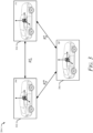
- FIG. 1 illustrates a conceptual diagram of an example environment 100 for secure camera based IMU calibration for stationary systems.
- the environment 100 includes a vehicle 102 that is undergoing IMU mounting calibration by a calibration system 104.
- the environment 100 represents a controlled environment, such as a vehicle factory or vehicle service station, where components of the vehicle 102 are initialized to an original baseline of settings or are reprogrammed with official updates to the initial settings.
- the vehicle 102 can represent other types of vehicles including other types of road vehicles (e.g., a car, motorcycle, bus, tractor, semi-trailer truck), railed vehicles (e.g., a train), watercraft (e.g., a boat), aircraft (e.g., an airplane), spacecraft (e.g., satellite), and the like.
- road vehicles e.g., a car, motorcycle, bus, tractor, semi-trailer truck
- railed vehicles e.g., a train
- watercraft e.g., a boat
- aircraft e.g., an airplane
- spacecraft e.g., satellite
- the vehicle 102 includes an IMU 106 and a camera system 108.
- the IMU 106 generates IMU data, which is compensated with IMU calibration data 110 that has been produced by analyzing camera images 112 captured by at least two cameras of the camera system 108.
- the IMU 106 is described as being a single IMU.
- the vehicle 102 includes multiple IMUs.
- the IMU 106 may include more than one IMU, each positioned at different locations on the vehicle 102 to obtain precise IMU data for different vehicle regions.
- multiple IMUs of the IMU 106 may be positioned at same locations of the vehicle 102, for increased safety, e.g., providing redundancy in the IMU data generated on-vehicle.
- the camera system 108 is used by the vehicle 102 for detecting objects from the camera images 112 that are present on or near a roadway that can impact how or whether the vehicle 102 can continue to travel or park.
- Each camera of the camera system 108 is configured to capture images for a particular region of interest at least partially surrounding the vehicle 102, which is referred to as a field of view.
- components of the camera system 108 can be installed on, mounted to, or integrated with any part of the vehicle 102, such as in a front, back, top, bottom, corner, or side portion of the vehicle 102, a bumper, a side mirror, part of a headlight and/or taillight, a tailgate, a trunk lid, or at any other exterior facing location of the vehicle 102.
- the camera system 108 includes a camera 108-1, a camera 108-2, a camera 108-3, a camera 108-4, and a camera 108- n .
- the camera 108-1 is a first end (e.g., front end) facing camera of the vehicle 102
- the camera 108-2 is a second, opposite end (e.g., rear end) facing camera of the vehicle 102.
- the camera 108-3 is a first side (e.g., driver side) facing camera of the vehicle 102
- the camera 108-4 is a second, opposite side (e.g., passenger side) facing camera of the vehicle 102.
- the camera 108- n is a center positioned camera of the vehicle 102.
- the cameras 108-1 and 108-2 or the cameras 108-3 and 108-4 are corner cameras placed at different corner positions of the vehicle 102.
- the camera 108-1 and the camera 108-2 are positioned at opposite corners of the vehicle 102.
- the camera 108-3 and the camera 108-4 may be positioned at different, opposite, corners.
- opposite corners refers to a combination of front passenger side and rear driver side corners of the vehicle 102 or a combination of front driver side and rear passenger side corners of the vehicle 102.
- Opposite sides include a combination of front and rear ends or passenger and driver sides of the vehicle 102.
- the camera 108-1 is configured to provide a field of view 120-1
- the camera 108-2 is configured to provide a field of view 120-2
- the camera 108- n configured to provide a field of view 120- n (not shown).
- the camera system 108 can have more than five cameras or fewer cameras.
- the camera system 108 can be used to calibrate the IMU 106, e.g., to compensate for mounting errors that misalign the IMU 106 with respect to a vehicle coordinate system of the vehicle 102. However, careful selection of cameras to be used for capturing the camera images 112 is needed.
- the camera system 108 includes at least two cameras with opposing field of views. Opposing field of views are considered to be field of views that project from cameras positioned at opposite sides or opposite corners of the vehicle 102.
- the camera 108-1 and the camera 108-2 project opposing field of views in that the field of view 120-1 projects in front of the vehicle 102 and the field of view 120-2 projects out the rear end of the vehicle 102.
- Other considerations in selecting the cameras for the camera system 108 to allow the IMU calibration data 110 to be computed include choosing cameras that have a minimum separation distance and/or a maximum separation height between them. This is described in greater detail in view of the other FIGS. 2-4 .
- the camera system 108 can include its own computer hardware or may be at least partially controlled by computer hardware of the vehicle 102, which can be same or different than vehicle components that control the IMU 106. For simplicity of the drawings, these components are not shown in the drawings.
- the vehicle 102 includes computer hardware (e.g., a controller, a control unit, a processor, programmable logic) configured to control the camera system 108 and the IMU 106 in a coordinated manner to capture and manage the camera images 112 stored on the vehicle 102.
- the IMU calibration data 110 may be stored by the vehicle 102 in a different CRM than the camera images 112.
- the vehicle 102 can maintain the camera images 112 and the IMU calibration data 110 on the same CRM, in other examples.
- the computer hardware of the vehicle 102 can calibrate the IMU 106 with the IMU calibration data 110 after the IMU calibration data 110 is generated based on the camera images 112.
- the vehicle 102 may include hardware or logic to generate the IMU calibration data 110 on the vehicle 102.
- the IMU calibration data 110 is generated offline (e.g., outside the vehicle 102 computer hardware) using different hardware within the environment 100.
- Computer hardware of the calibration system 104 is configured to obtain the camera images 112 from the vehicle 102 and generate the IMU calibration data 110 that it sends back to the vehicle 102 enabling the computer hardware of the vehicle 102 to calibrate the IMU 106.
- the IMU 106 can produce IMU data, and the IMU calibration data 110 can be used by the computer hardware of the vehicle 102 to compensate the IMU data before being output for use by vehicle functions.
- the computer hardware of the vehicle 102 can execute operations that cause the generation of IMU data, which is closely aligned to a vehicle coordinate system of the vehicle 102, thereby preventing any mounting errors associated with the IMU 106 from corrupting the IMU data.
- Compensated IMU data from the IMU 106 is output ready for use in performing other functions of the vehicle 102.
- the calibration system 104 includes a calibration unit 114, a communication link 116, and a plurality of calibration targets 118.
- the communication link 116 enables transmission of data between computer hardware of the vehicle 102 and the calibration system 104.
- the communication link 116 may be wired or wireless.
- the communication link 116 may be a secure link utilizing encryption and authentication techniques that prevent malicious access to the vehicle 102 and/or to the calibration system 104. With the communication link 116 established, the vehicle 102 can send the camera images 112 captured with the camera system 108, and in response, receive the IMU calibration data 110 generated by the calibration system 104.
- the calibration targets 118 are shown as calibration target 118-1, calibration target 118-2, calibration target 118-3, and calibration target 118-4. Each of the calibration targets 118 is placed in a field of view of a different camera of the camera system 108.
- the calibration target 118-1 is in the field of view 120-1
- the calibration target 118-2 is positioned in the field of view 120-2
- the calibration target 118-3 is positioned in the field of view 120-3
- the calibration target 118-4 is positioned in the field of view 120-4.
- Each of the calibration targets 118 is configured to display content, including optically encoded data, which enables recalibration of the IMU 106.
- the content is displayed by each of the calibration targets 118 at a precise position relative the vehicle 102 and the cameras of the camera system 108. This allows alignment markers within the encoded data to be used for determining the vehicle coordinate system from the camera images 112.
- the encoded data prevents spoofing of the calibration targets 118 and further prevents the calibration system 104 from incorrectly generating the IMU calibration data 110 for a wrong type (e.g., make, model, year, serial number, vehicle identification number) of the vehicle 102 and/or the IMU 106.
- a wrong type e.g., make, model, year, serial number, vehicle identification number
- the calibration system 104 may refrain from communicating with the vehicle 102 and not generate the IMU calibration data 110.
- the calibration unit 114 of the calibration system 104 controls the content presented on the calibration targets 118 and generates the IMU calibration data 110 from the camera images 112 of the content.
- the calibration unit 114 is configured to receive the camera images 112 of the calibration targets 118 captured by the camera system 108. Based on the camera images 112 received via the communication link 116, the calibration unit 114 is configured to determine a realignment of a coordinate system of the IMU 106.
- the realignment includes rotational corrections to axis of the IMU coordinate system to bring a frame of reference of the IMU 106 into agreement with that of the vehicle 102.
- the calibration unit 114 causes the IMU calibration data 110 to be conveyed to the IMU 106 over the communication link 116.
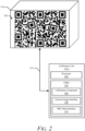
- FIG. 2 illustrates a conceptual diagram of a calibration unit 114-1 configured to perform secure camera based IMU calibration for stationary systems.
- the calibration unit 114-1 is an example of the calibration unit 114 and is described in the context of FIG. 1 .
- the calibration unit 114-1 is shown operatively and communicatively coupled to at least two of the calibration targets 118, each having its own respective screen 200 for displaying graphical or other optically recognizable content.
- the calibration unit 114-1 obtains sufficient information from content on the screens 200 to improve calculations (e.g., vehicle metrics) inferred using the IMU 106.
- calculations e.g., vehicle metrics
- both, vehicle slope and vehicle bank calculations can be improved.
- the calibration unit 114-1 includes a processor 202 and a CRM 204.
- the CRM 204 stores instructions and/or data, that when executed by the processor 202, implements a calibration component 206, a camera image interface 208, and an IMU data interface 210.
- the calibration unit 114-1 shares a communication link 212 with each of the calibration targets 118.
- the camera image interface 208 configures the calibration unit 114-1 to receive images of the calibration targets 118 as they appear in two opposing field of views of at least two cameras from the camera system 108. For example, via the communication link 116, the camera image interface 208 receives one of the camera images 112 captured by the camera 108-1 that is of the calibration target 118-1 within the field of view 120-1. In addition, as captured by the camera 108-2, the camera image interface 208 receives at least one more of the camera images 112, which is an image of the calibration target 118-2 within the field of view 120-2, which is opposite the field of view 120-1. Similarly, the camera image interface 208 can receive images of the other calibration targets 118, as they appear in images captured by the cameras 108-3 and 108-4, as the calibration targets 118-3 and 118-4 appear, respectively, in the field of views 120-3 and 120-4.
- the IMU data interface 210 configures the calibration unit 114-1 to send the IMU calibration data 110 to the vehicle 102 over the communication link 116.
- the calibration component 206 generates the IMU calibration data 110 based on the camera images 112 received at the camera image interface 208.
- the IMU calibration data 110 is transmitted by the IMU data interface 210 to the vehicle 102 for use in compensating IMU data produced from the IMU 106.
- the calibration component 206 is responsible for generating the IMU calibration data 110 to fill an output buffer of the IMU data interface 210 based on information analyzed from an input buffer of the camera image interface 208.
- the calibration component 206 selects certain cameras to be used for IMU mounting calibration, causes certain content to be displayed in their respective fields of view, and, based on data encoded in the camera images 112 taken of the calibration targets 118, precisely aligns the IMU 106 to the vehicle coordinate system of the vehicle 102.
- the calibration component 206 obtains information about position, viewing angle, and field of view size, of each camera of the camera system 108 to identify suitable pairs of cameras with opposing or opposite field of views. Not all cameras of the camera system 108 may be suitable pairings; a minimum height-similarity between the two cameras may be used to ensure that, because of trigonometry math, their relative positioning can satisfactorily resolve a small mounting error (e.g., angle error) in the IMU 106.
- the calibration component 206 can obtain a relative separation height between the camera 108-1 and the camera 108-2.
- the calibration component 206 can obtain a relative separation distance between the camera 108-1 and the camera 108-2, as well.
- the cameras 108-1 and 108-2 are too close in separation distance (e.g., not on opposite sides, not on opposite corners, not on opposite ends) on the vehicle 102, they may not be suitable for calibrating the IMU 106 for improving vehicle bank and roll computations. Likewise, if the cameras 108-1 and 108-2 are too far apart in height relative the vehicle coordinate system, they may not be suitable for calibrating the IMU 106 for improving vehicle bank and roll computations. However, if sufficiently far apart in distance, and sufficiently close in height, the cameras 108-1 and 108-2 may be selected for calibration for improving vehicle bank and roll computations of the IMU 106.
- the calibration component 206 may select, from among multiple different cameras 108-1 to 108- n of the vehicle 102, the camera 108-1 and the camera 108-2 to use for calibrating the IMU 106 based on whether the relative separation height between the camera 108-1 and the camera 108-2 satisfies a height threshold (e.g., less than one hundredth of a meter).
- a height threshold e.g., less than one hundredth of a meter.
- the calibration component 206 may select, from among multiple different cameras 108-1 to 108- n of the vehicle 102, the camera 108-1 and the camera 108-2 to use for calibrating the IMU based on whether the relative separation distance between the camera 108-1 and the camera 108-2 satisfies a distance threshold (e.g., more than several meters).
- the calibration component 206 communicates with the calibration targets 118 to display content on the respective screens 200, which appear in the field of views 120 of the selected cameras from the camera system 108 and in the camera images 112.
- the calibration component 206 controls the presentation and format of the content displayed at each calibration target 118.
- Each of the respective screens 200 can display the same, similar, or different content.
- the calibration component 206 may output, for display on a respective screen 200 of the calibration target 118-1, a first optical pattern.
- the calibration component 206 may output, for display on a respective screen 200 of the calibration target 118-2, a second optical pattern.
- the optical patterns may be different from one calibration target 118 to the next, however, each may include a portion of encoded data. When captured by the cameras 108-1 and 108-2 and/or 108-3 and 108-4, the encoded data appears in pixels of the camera images 112.
- the encoded data serves multiple purposes. A comparison of the expected encoded data with the detected encoded data in the camera images 112 activates or conditions the IMU 106 calibration. In addition, the encoded data is used as alignment features to generate the IMU calibration data 110 to calibrate the IMU 106. As such, the content that appears on the respective screens 200 of the calibration targets 118 provides a security purpose to prevent unintentional or malicious calibrations, as well as a functional purpose for calibrating the IMU 106.
- the calibration targets 118 can be controlled by the calibration component to display content like that shown in FIG. 2 .
- Included in this optical pattern example is encoded data, including reference alignment regions interspersed with embedded security features, including extra regions of noise.
- the alignment regions can be used to generate the IMU calibration data 110.
- the optical pattern may be displayed or projected by the calibration targets 118 on a plane that is perpendicular to horizontal plane that includes the vehicle 102 and one of the cameras 108-1, 108-2, ..., and so forth. This can optimize the detection of vehicle bank and roll angles during the vehicle coordinate system and the IMU coordinate system alignment and the IMU 106 calibration.
- the embedded security features can be used to authenticate the underlying calibration being performed.
- an embedded key can be presented by the calibration target 118 to use as a public key for authenticating and verifying that the calibration process is allowed to execute.
- a barcode or QR code can indicate a secure website or internet protocol (IP) address for allowing bidirectional communication between the calibration component 206 and the vehicle 102.
- Additional security measures can include changing the calibration targets 118, periodically, to further prevent unauthorized reprogramming or calibration of the IMU 106. This ensures the IMU 106 is not recalibrated unless the calibration component 206 can validate certain parameters are verifiable from the camera images 112. In this way, the calibration component 206 is less likely to be compromised by a spoofing attack that tries to mimic the encoded data on false calibration targets positioned around the vehicle 102, e.g., when the vehicle 102 is parked outside the environment 100.
- FIG. 3 illustrates a conceptual diagram of a calibration component 206-1 configured to perform secure camera based IMU calibration for stationary systems.
- the calibration component 206-1 is an example of the calibration component 206 and described in the context of FIGS. 1 and 2 .
- the calibration component 206-1 is configured to compensate for IMU mounting errors in the vehicle 102 by generating the IMU calibration data 110 to calibrate the IMU 106.
- the calibration component 206-1 checks whether to continue or refrain from generating the IMU calibration data 110. Based on data encoded in the image of the calibration target 118-1 and data encoded in the image of the calibration target 118-2, it is determined whether the calibration targets 118-1 and 118-2 are valid for calibrating the IMU 106 of the vehicle 102.
- the calibration component 206-1 Responsive to determining that the calibration targets 118-1 and 118-2 are not valid for calibrating the IMU 106 (e.g., one of more of the camera images 112 does not include the encoded data the calibration component 206-1 expects to see), the calibration component 206-1 refrains from executing a function to generate the IMU calibration data 110. Otherwise, e.g., responsive to validating the calibration targets 118-1 and 118-2 from the camera images 112, the calibration component 206-1 calls on the function to generate the IMU calibration data 110.
- the IMU calibration data 110 is generated by the calibration component 206-1 to remove relative rotation between an IMU coordinate system 302 and a vehicle coordinate system 304, irrespective of ground-truth conditions 306 of the environment 100.
- the IMU calibration data 110 can include adjustments to parameters of the IMU 106 to rotationally align the IMU coordinate system 302 with the vehicle coordinate system 304 after isolating relative rotations that each has to the ground-truth conditions 306 (e.g., a gravity vector).
- the ground-truth conditions 306 includes the true gravitational vector for the environment 100, for instance, as measured by a highly calibrated IMU located in the environment 100 outside the vehicle 102, and operatively coupled to the calibration component 206-1.
- the ground-truth conditions 306 may be obtained by the calibration component 206-1 in one or more ways (e.g., from input by a technician, from input from a file about the environment 100, from other equipment in the environment 100 or the calibration system 104).
- the calibration component 206-1 obtains IMU data from the IMU 106 as a frame of reference to determine the IMU coordinate system 302 with respect to the ground-truth conditions 306. Based on the image of the calibration target 118-1 and the image of the calibration target 118-2, the vehicle coordinate system 304 is likewise established with respect to the ground-truth conditions 306. By comparing the vehicle coordinate system 304 to the IMU coordinate system 302, a relative rotation between the two coordinate systems 304 and 302 can be computed, which is isolated from the influence of the ground-truth conditions 306. For example, a first relative rotation R g m between the IMU coordinate system 302 ( m ) and the ground-truth conditions 306 ( g ) is computed.
- a second relative rotation R g v between the vehicle coordinate system 304 ( v ) and the ground-truth conditions 306 ( g ) is computed.
- a third relative rotation R m v between just the vehicle coordinate system 304 ( v ) and the IMU coordinate system 302 ( m ) is computed.
- This third relative rotation R m v removes the relative rotation influence of the ground-truth conditions 306 ( g ) and indicates a relative rotation between axis of the IMU coordinate system 302 and axis the vehicle coordinate system 304 alone.
- the IMU calibration data 110 is determined by determining adjustments to the parameters of the IMU 106 that reduce this third relative rotation between the IMU coordinate system 302 and the vehicle coordinate system 304 as much as possible, or at least, to within an acceptable level of tolerance, such as one half degree in any direction.
- the IMU calibration data 110 is provided to the vehicle 102 to allow the vehicle 102 to align IMU data output from the IMU 106 for use by functions that are aligned with the vehicle coordinate system 304.
- the calibration component 206-1 can cause the calibration system 104 to transmit the IMU calibration data 110 to the vehicle 102 over the communication link 116.
- the IMU calibration data 110 indicates how to compensate IMU data to align the IMU coordinate system 302 of the IMU 106 with the vehicle coordinate system 304 of the vehicle 102, which can effectively prevent erroneous IMU data caused by mounting errors in the installation of parts of the vehicle 102 and/or the IMU 106.
- the computer hardware of the vehicle 102 can reprogram settings and parameters of the IMU 106 to compensate for IMU mounting errors by calibrating the IMU 106 using the IMU calibration data 110. After the IMU data is aligned to the vehicle coordinate system 304 and compensated for the IMU mounting errors in the vehicle 102, the vehicle 102 may use the IMU data output from the IMU 106 for executing vehicle functions that act on the IMU data.
- FIG. 4 illustrates a flow diagram of an example process 400 for performing secure camera based IMU calibration for stationary systems.
- the process 400 is described primarily in the context of being performed by the calibration system 104 using the communication link 116 to exchange information with the vehicle 102, which is parked and stationary in the environment 100.
- the processor 202 with access to the CRM 204 can execute instructions to perform the process 400 and executing the calibration components 206 and 206-1, the camera image interface 208, and the IMU data interface 210.
- Operations (also referred to as steps) of the process 400 are numbered in this example from 402 to 414. However, this numbering does not necessarily imply a specific order of operations.
- the steps of the process 400 may be rearranged, skipped, repeated, or performed in different ways than the specific way it is shown in the diagram of FIG. 4 .
- an image of a first calibration target within a first camera field of view is received from a first camera of a stationary vehicle.
- an image of a second calibration target within a second camera field of view that is opposite the first camera field of view is received from a second camera of the stationary vehicle.
- the calibration system 104 can select at least one pair of cameras from the vehicle 102 to calibrate the IMU 106.
- the calibration system 104 selects the camera 108-1, which is front facing, and has the calibration target 118-1 within the field of view 120-1.
- the calibration system selects the camera 108-2 that is rear facing and has the calibration target 118-1 within the field of view 120-2, which is opposite the field of view 120-1.
- more than two calibration targets 118 and/or more than two cameras of the camera system 108 are used. With a minimum of two images employed, and preferably three images for discerning both slope and bank angles, the vehicle coordinate system 304 can be accurately determined. For example, at 402, an image of a third calibration target within the first camera field of view may be received by the processor 202. An image of the third calibration target or a fourth calibration target within the second camera field of view may be received by the processor 202. Using two, three, or even more images of calibration targets can cause the vehicle coordinate system 304 to be computed with a higher degree of precision and/or a higher degree of confidence because of the additional alignment reference indicators and encoded data available from the additional camera images.
- data encoded in the image of the first calibration target and data encoded in the image of the second calibration target is identified.
- the calibration system 104 communicates over the communication link 116 to cause the vehicle 102 to control the camera system 108 to capture the camera images 112.
- the calibration system 104 identifies features within optical patterns of the calibration targets 118-1 and 118-2, which include encoded data used for determining the vehicle coordinate system 304.
- the camera 108-1 may have a first viewing angle to the calibration target 118-1
- the camera 108-2 may have a second viewing angle to the calibration target 118-2.
- the optical pattern appears different in the camera images 112.
- the first and second viewing angles can be the same or different.
- the first and second viewing angles are set by the calibration system 104 to precise angles that cause a unique, respective optical pattern in the camera images 112. By setting the viewing angles to precise angles, spoofing of calibration targets and the calibration system 104 is prevented, and a precise vehicle coordinate system can be inferred as a frame of reference for calibrating the IMU 106.
- the calibration system 104 compares the respective optical pattern at each of the calibration targets 118-1 and 118-2 with a corresponding expected pattern for that particular calibration target to determine whether that particular calibration target is valid for calibrating the IMU. If the calibration targets 118-1 and 118-2 are not precisely positioned near the cameras 108-1 and 108-2, with precise viewing angles applied, the optical patterns within the camera images 112 may not include recognizable features that can be used to determine the vehicle coordinate system.
- the encoded data may indicate a make, model, serial number, vehicle identification number, or other identifier of the vehicle 102 and the IMU 106 being calibrated. If the encoded data within the camera images 112 is not validated by the calibration system 104 as being authentic, then the IMU 106 is not re-calibrated. For example, if at 408, it is determined that the first and second calibration targets are valid for calibrating the IMU, then the YES branch is taken and the process 400 continues to step 410. Otherwise, if it is determined that the first and second calibration targets are not valid for calibrating the IMU, then the NO branch is taken and the process 400 continues to step 414. Calibration of the IMU 106 can be conditioned like this, e.g., based on whether the information received from the controller of the vehicle 102 satisfies entry conditions for IMU calibration, in one or more ways.
- the computer hardware of the vehicle 102 sends information to the calibration system 104 that indicates whether the vehicle 102 is in a state that is acceptable for IMU calibration.
- the vehicle 102 When in the environment 100, the vehicle 102 is in a controlled environment where the vehicle 102 can be placed in a special programming mode, which cannot be accessed from outside the environment 100 or without using special equipment, such as the calibration system 104.
- Information about the vehicle conditions e.g., whether the vehicle 102 is a parked state, whether the controller and or the vehicle 102 is in programming mode, whether the vehicle 102 is in the environment 100
- the calibration system 104 is authorized when the information satisfies entry conditions for IMU calibration.
- the calibration system 104 refrains from generating the IMU calibration data 110 for calibrating the IMU 106, unless it is absolutely safe to do so.
- the IMU 106 can be calibrated to align the IMU data output from the IMU 106 with the vehicle coordinate system 304.
- a vehicle coordinate system with respect to ground-truth conditions outside the vehicle is determined. For example, a first relative rotation R g m between the IMU coordinate system 302 and the ground-truth conditions 306 is computed, in addition to a second relative rotation R g v between the vehicle coordinate system 304 and the ground-truth conditions 306.
- a third relative rotation R m v between the vehicle coordinate system 304 and the IMU coordinate system 302 is computed, which provides a direct relationship between the IMU 106 and the vehicle frame of reference, regardless of deviations in each with respect to the ground-truth conditions 306.
- the vehicle frame of reference i.e., the vehicle coordinate system 304
- the vehicle coordinate system 304 is related to the vehicle chassis (e.g., the vehicle frame). Therefore, the vehicle coordinate system 304 is independent of changes in vehicle part positions due to variable suspensions, uneven tire inflations, variable torquing, or other variables that do not cause relative mounting errors between the IMU 106 and the vehicle chassis and the vehicle coordinate system 304.
- a relative rotation between axis of the IMU coordinate system 302 and the vehicle coordinate system 304 is computed to generate the IMU calibration data 110, which when applied by the vehicle 102 to the parameters of the IMU 106, causes IMU data to be output aligned to the vehicle coordinate system 304, regardless of mounting errors in the installation of the IMU 106.
- information is output to enable the stationary vehicle to calibrate the IMU to align IMU data output from the IMU with the vehicle coordinate system by compensating for IMU mounting errors in the vehicle.
- the calibration system 104 is configured to output information to the vehicle 102.
- the information output includes the IMU calibration data 110, which is transmitted from the calibration system 104 to the vehicle 102 where the computer hardware of the vehicle 102 adjusts the IMU 106 to be rotationally aligned with the vehicle coordinate system 304.
- IMU data output from the IMU 106 during operation of the vehicle 102 is compensated to be aligned to the vehicle coordinate system 304, which allows functions of the vehicle 102 to use the IMU data directly, with confidence that it is free from errors. This is true even if the IMU 106 is mounted outside tolerances specified for mounting the IMU 106 to a PCB assembly of the vehicle 102.
- "at least one of: a, b, or c” is intended to cover a, b, c, a-b, a-c, b-c, and a-b-c, as well as any combination with multiples of the same element (e.g., a-a, a-a-a, a-a-b, a-a-c, a-b-b, a-c-c, b-b, b-b-b, b-b-c, c-c, and c-c-c or any other ordering of a, b, and c).
Landscapes
- Engineering & Computer Science (AREA)
- Physics & Mathematics (AREA)
- General Physics & Mathematics (AREA)
- Radar, Positioning & Navigation (AREA)
- Remote Sensing (AREA)
- Computer Vision & Pattern Recognition (AREA)
- Theoretical Computer Science (AREA)
- Manufacturing & Machinery (AREA)
- Automation & Control Theory (AREA)
- Closed-Circuit Television Systems (AREA)
Claims (15)
- Verfahren, umfassend, dass:von einer ersten Kamera (108-1, 108-3) eines stationären Fahrzeugs (102) ein Bild eines ersten Kalibrierungsziels (118-1, 118-3) innerhalb eines ersten Kamerasichtfelds (120-1, 120-3) der ersten Kamera empfangen (402) wird;von einer zweiten Kamera (108-2, 108-4) des stationären Fahrzeugs ein Bild eines zweiten Kalibrierungsziels (118-2, 118-4) innerhalb eines zweiten Kamerasichtfelds (120-2, 120-4) der zweiten Kamera empfangen (404) wird, wobei das zweite Kamerasichtfeld dem ersten Kamerasichtfeld entgegengesetzt ist;auf Basis der codierten Daten im Bild des ersten Kalibrierungsziels und codierten Daten im Bild des zweiten Kalibrierungsziels bestimmt (408) wird, ob das erste und zweite Kalibrierungsziel zum Kalibrieren einer Trägheitsmesseinheit (106) IMU des stationären Fahrzeugs gültig sind;als Reaktion auf das Bestimmen, dass das erste und zweite Kalibrierungsziel zum Kalibrieren der IMU gültig sind, auf Basis des Bildes des ersten Kalibrierungsziels und des Bildes des zweiten Kalibrierungsziels, ein Fahrzeugkoordinatensystem in Bezug auf Bodenwahrheitsbedingungen außerhalb des Fahrzeugs erstellt (410) wird; undInformationen ausgegeben werden, um es dem stationären Fahrzeug zu ermöglichen, IMU-Montagefehler im Fahrzeug durch Kalibrieren der IMU zu kompensieren (412), um die von der IMU ausgegebenen IMU-Daten mit dem Fahrzeugkoordinatensystem auszurichten.
- Verfahren nach Anspruch 1, wobei die erste Kamera eine nach vorne gerichtete Kamera des Fahrzeugs umfasst und die zweite Kamera eine nach hinten gerichtete Kamera des Fahrzeugs umfasst.
- Verfahren nach einem der Ansprüche 1 oder 2, wobei die erste Kamera eine erste zur Seite gerichtete Kamera des Fahrzeugs umfasst und die zweite Kamera eine zur entgegengesetzten Seite gerichtete Kamera des Fahrzeugs umfasst.
- Verfahren nach einem der Ansprüche 1 -3, wobei die erste Kamera eine erste zur vorderen Ecke gerichtete Kamera des Fahrzeugs umfasst und die zweite Kamera eine zur hinteren Ecke gerichtete Kamera des Fahrzeugs umfasst.
- Verfahren nach einem der Ansprüche 1 -4, ferner umfassend, dass:von einer dritten Kamera des stationären Fahrzeugs ein Bild eines dritten Kalibrierungsziels innerhalb eines dritten Kamerasichtfelds empfangen wird; von einer vierten Kamera des stationären Fahrzeugs ein Bild eines vierten Kalibrierungsziels innerhalb eines vierten Kamerasichtfelds empfangen wird, das dem dritten Kamerasichtfeld gegenüberliegt;auf Basis der codierten Daten im Bild des dritten Kalibrierungsziels und codierten Daten im Bild des vierten Kalibrierungsziels bestimmt wird, ob das dritte und vierte Kalibrierungsziel zum Kalibrieren der IMU gültig sind; undals Reaktion auf das Bestimmen, dass das dritte und vierte Kalibrierungsziel zum Kalibrieren der IMU gültig sind, das Fahrzeugkoordinatensystem ferner basierend auf dem Bild des dritten Kalibrierungsziels und dem Bild des vierten Kalibrierungsziels erstellt wird.
- Verfahren nach einem der Ansprüche 1-5, wobei das Kalibrieren der IMU, um die von der IMU ausgegebenen IMU-Daten mit dem Fahrzeugkoordinatensystem auszurichten, umfasst, dass:von einer Steuerung des stationären Fahrzeugs Informationen empfangen werden, die angeben, dass das stationäre Fahrzeug in einer gesteuerten Kalibrierungsumgebung geparkt ist;die Kalibrierung der IMU basierend auf den von der Steuerung empfangenen Informationen autorisiert wird; undals Reaktion auf das Autorisieren der Kalibrierung der IMU die IMU kalibriert wird, um die von der IMU ausgegebenen IMU-Daten mit dem Fahrzeugkoordinatensystem auszurichten.
- Verfahren nach einem der Ansprüche 1-6, wobei:die erste Kamera einen ersten Betrachtungswinkel relativ zu dem ersten Kalibrierungsziel aufweist;die zweite Kamera einen zweiten Betrachtungswinkel relativ zu dem zweiten Kalibrierungsziel aufweist; unddas Verfahren ferner umfasst, dass:der erste und zweite Betrachtungswinkel auf präzise Winkel eingestellt werden, die ein jeweiliges eindeutiges optisches Muster bewirken, das codierte Daten an jedem des ersten und zweiten Kalibrierungsziels umfasst; unddas jeweilige optische Muster an jedem des ersten und zweiten Kalibrierungsziels mit einem entsprechenden erwarteten Muster für dieses bestimmte Kalibrierungsziel verglichen wird, um zu bestimmen, ob dieses bestimmte Kalibrierungsziel zum Kalibrieren der IMU gültig ist.
- Verfahren nach einem der Ansprüche 1 -7, wobei das erste und zweite Kalibrierungsziel jeweilige Bildschirme umfassen, die das erste und zweite Kalibrierungsziel anzeigen.
- Verfahren nach Anspruch 8, ferner umfassend, dass:zur Anzeige auf einem jeweiligen Bildschirm des ersten Kalibrierungsziels ein erstes optisches Muster ausgegeben wird, das die codierten Daten umfasst, die im Bild des ersten Kalibrierungsziels erscheinen; undzur Anzeige auf einem jeweiligen Bildschirm des zweiten Kalibrierungsziels ein zweites optisches Muster ausgegeben wird, das die codierten Daten umfasst, die im Bild des zweiten Kalibrierungsziels erscheinen.
- Verfahren nach einem der Ansprüche 1-9, ferner umfassend, dass:eine relative Trennungshöhe zwischen der ersten Kamera und der zweiten Kamera erhalten wird; undaus mehreren verschiedenen Kameras des Fahrzeugs die erste Kamera und die zweite Kamera zur Verwendung zum Kalibrieren der IMU basierend darauf ausgewählt wird, ob die relative Trennungshöhe zwischen der ersten Kamera und der zweiten Kamera einen Höhenschwellenwert erfüllt.
- Verfahren nach Anspruch 10, ferner umfassend, dass:eine relative Trennungsdistanz zwischen der ersten Kamera und der zweiten Kamera erhalten wird; unddie erste Kamera und die zweite Kamera zur Verwendung zum Kalibrieren der IMU ferner basierend darauf ausgewählt werden, ob die relative Trennungsdistanz zwischen der ersten Kamera und der zweiten Kamera einen Distanzschwellenwert zum Korrigieren von Fehlern im Montagewinkel der IMU relativ zum stationären Fahrzeug erfüllt.
- Verfahren nach einem der Ansprüche 1-11, wobei das Ausgeben von Informationen, um es dem stationären Fahrzeug zu ermöglichen, die IMU zu kalibrieren, um die von der IMU ausgegebenen IMU-Daten mit dem Fahrzeugkoordinatensystem auszurichten, das Senden von Informationen an das stationäre Fahrzeug zum Kompensieren der IMU-Daten für die relative Drehung zwischen dem Fahrzeugkoordinatensystem und einem Koordinatensystem der IMU umfasst.
- Verfahren nach einem der Ansprüche 1-12, wobei die IMU-Daten von der IMU zum Ausführen von Funktionen des stationären Fahrzeugs ausgegeben werden, die auf die IMU-Daten einwirken, nachdem die IMU-Daten mit dem Fahrzeugkoordinatensystem ausgerichtet und hinsichtlich der IMU-Montagefehler im Fahrzeug kompensiert wurden.
- System, umfassend einen Prozessor, der konfiguriert ist, um das Verfahren nach einem der Ansprüche 1-13 durchzuführen.
- Computerlesbares Speichermedium, das Anweisungen umfasst, die, wenn sie ausgeführt werden, einen Prozessor veranlassen, das Verfahren nach einem der Ansprüche 1-13 durchzuführen.
Applications Claiming Priority (2)
| Application Number | Priority Date | Filing Date | Title |
|---|---|---|---|
| US202163229177P | 2021-08-04 | 2021-08-04 | |
| US17/660,242 US12254647B2 (en) | 2021-08-04 | 2022-04-22 | Secure camera based inertial measurement unit calibration for stationary systems |
Publications (3)
| Publication Number | Publication Date |
|---|---|
| EP4130678A1 EP4130678A1 (de) | 2023-02-08 |
| EP4130678B1 true EP4130678B1 (de) | 2024-04-17 |
| EP4130678B8 EP4130678B8 (de) | 2024-05-22 |
Family
ID=81580915
Family Applications (1)
| Application Number | Title | Priority Date | Filing Date |
|---|---|---|---|
| EP22171782.0A Active EP4130678B8 (de) | 2021-08-04 | 2022-05-05 | Sichere kamerabasierte kalibrierung von trägheitsmesseinheiten für stationäre systeme |
Country Status (3)
| Country | Link |
|---|---|
| US (1) | US12254647B2 (de) |
| EP (1) | EP4130678B8 (de) |
| CN (1) | CN115704699B (de) |
Families Citing this family (5)
| Publication number | Priority date | Publication date | Assignee | Title |
|---|---|---|---|---|
| KR20230158335A (ko) * | 2022-05-11 | 2023-11-20 | 현대자동차주식회사 | 차량 및 그 제어 방법 |
| CN115272494B (zh) * | 2022-09-29 | 2022-12-30 | 腾讯科技(深圳)有限公司 | 相机与惯性测量单元的标定方法、装置和计算机设备 |
| TWI903296B (zh) * | 2023-12-06 | 2025-11-01 | 鴻海精密工業股份有限公司 | 安裝角度標定方法、車載裝置及儲存介質 |
| CN118115593B (zh) * | 2024-01-29 | 2025-11-04 | 江铃汽车股份有限公司 | 车载侧视相机系统下线标定方法、装置、存储介质及设备 |
| KR102936758B1 (ko) * | 2024-12-27 | 2026-03-11 | 주식회사 긴트 | 작업차량의 imu 보정 방법 및 그 장치 |
Family Cites Families (13)
| Publication number | Priority date | Publication date | Assignee | Title |
|---|---|---|---|---|
| US8855929B2 (en) * | 2010-01-18 | 2014-10-07 | Qualcomm Incorporated | Using object to align and calibrate inertial navigation system |
| US9160980B2 (en) * | 2011-01-11 | 2015-10-13 | Qualcomm Incorporated | Camera-based inertial sensor alignment for PND |
| US9688200B2 (en) * | 2013-03-04 | 2017-06-27 | Magna Electronics Inc. | Calibration system and method for multi-camera vision system |
| US9631956B2 (en) * | 2014-01-03 | 2017-04-25 | Google Technology Holdings LLC | Methods and systems for calibrating sensors of a computing device |
| CN107850436B (zh) | 2015-05-23 | 2021-03-05 | 深圳市大疆创新科技有限公司 | 使用惯性传感器和图像传感器的传感器融合 |
| US10012517B2 (en) * | 2016-08-01 | 2018-07-03 | Infinity Augmented Reality Israel Ltd. | Method and system for calibrating components of an inertial measurement unit (IMU) using scene-captured data |
| US11435456B2 (en) | 2017-12-28 | 2022-09-06 | Lyft, Inc. | Sensor calibration facility |
| US11538188B1 (en) * | 2019-06-05 | 2022-12-27 | Hunter Engineering Company | Methods for spatial calibration of vehicle ADAS service system |
| CN110296691B (zh) * | 2019-06-28 | 2020-09-22 | 上海大学 | 融合imu标定的双目立体视觉测量方法与系统 |
| US11403891B2 (en) | 2019-11-01 | 2022-08-02 | Gm Cruise Holdings Llc | Autonomous setup and takedown of calibration environment for vehicle sensor calibration |
| US10992928B1 (en) * | 2020-01-30 | 2021-04-27 | Facebook Technologies, Llc | Calibration system for concurrent calibration of device sensors |
| CN113847930A (zh) * | 2020-06-28 | 2021-12-28 | 图森有限公司 | 多传感器校准系统 |
| US12033434B1 (en) * | 2022-09-19 | 2024-07-09 | Amazon Technologies, Inc. | Inventory status determination with fleet management |
-
2022
- 2022-04-22 US US17/660,242 patent/US12254647B2/en active Active
- 2022-05-05 EP EP22171782.0A patent/EP4130678B8/de active Active
- 2022-06-30 CN CN202210767493.6A patent/CN115704699B/zh active Active
Also Published As
| Publication number | Publication date |
|---|---|
| US20230039129A1 (en) | 2023-02-09 |
| CN115704699B (zh) | 2026-03-31 |
| EP4130678A1 (de) | 2023-02-08 |
| US12254647B2 (en) | 2025-03-18 |
| CN115704699A (zh) | 2023-02-17 |
| EP4130678B8 (de) | 2024-05-22 |
Similar Documents
| Publication | Publication Date | Title |
|---|---|---|
| EP4130678B1 (de) | Sichere kamerabasierte kalibrierung von trägheitsmesseinheiten für stationäre systeme | |
| CN109584306B (zh) | 一种基于车辆定位的高级驾驶辅助标定系统及方法 | |
| CN111599036B (zh) | 车辆检测系统及车辆检测方法 | |
| US20210152784A1 (en) | Multi-camera calibration method for a vehicle moving along a vehicle assembly line | |
| US20240196092A1 (en) | Techniques to compensate for movement of sensors in a vehicle | |
| CN105139389B (zh) | 全景摄像机系统(vpm)与车辆动态 | |
| CN107685730B (zh) | 使用车辆侧倾的用于有风情况下的自主车辆的车道保持系统 | |
| US20170261599A1 (en) | Method of automatic sensor pose estimation | |
| US11940555B2 (en) | Radar apparatus for a vehicle and method of detecting misalignment | |
| KR102487201B1 (ko) | 레이더 센서 각도 에이밍 시스템 및 그 방법 | |
| CN108349469B (zh) | 用于确定传感器单元的取向的方法和设备 | |
| KR102183224B1 (ko) | 차량 레이더 오차 보정 시스템 및 그 방법 | |
| CN108696719A (zh) | 用于校准车辆的车辆摄像机的方法和设备 | |
| CN109308065B (zh) | 根据性能产品探测的车辆校准 | |
| WO2018232940A1 (zh) | 一种安全泊车方法及装置 | |
| JP2009204459A (ja) | 車両用慣性力センサおよび車両の傾斜検出方法 | |
| KR102227850B1 (ko) | 차량용 후방 카메라의 영상 보정 방법 | |
| EP4185973B1 (de) | Kamerasystemsicherheitskalibrierungsverfahren und kamera-pod-anordnung | |
| US20170102704A1 (en) | Automated Vehicle Object Detection Device With Level Detection | |
| KR102637830B1 (ko) | 위치 결정을 위한 방법, 전자 제어 장치 및 시스템 | |
| JP7188228B2 (ja) | 画像生成装置 | |
| CN118254817A (zh) | 车道偏离预警方法、电子设备、系统及存储介质 | |
| KR102714865B1 (ko) | 차량 실내 레이더 장치 및 이를 이용한 타겟 위치 검출 방법 | |
| US20250086755A1 (en) | Method and apparatus for capturing an image outside a motor vehicle, and motor vehicle | |
| US12091108B2 (en) | Methods and systems for a pitch angle recognition of a steering column in a vehicle |
Legal Events
| Date | Code | Title | Description |
|---|---|---|---|
| PUAI | Public reference made under article 153(3) epc to a published international application that has entered the european phase |
Free format text: ORIGINAL CODE: 0009012 |
|
| STAA | Information on the status of an ep patent application or granted ep patent |
Free format text: STATUS: THE APPLICATION HAS BEEN PUBLISHED |
|
| AK | Designated contracting states |
Kind code of ref document: A1 Designated state(s): AL AT BE BG CH CY CZ DE DK EE ES FI FR GB GR HR HU IE IS IT LI LT LU LV MC MK MT NL NO PL PT RO RS SE SI SK SM TR |
|
| STAA | Information on the status of an ep patent application or granted ep patent |
Free format text: STATUS: REQUEST FOR EXAMINATION WAS MADE |
|
| 17P | Request for examination filed |
Effective date: 20230704 |
|
| RBV | Designated contracting states (corrected) |
Designated state(s): AL AT BE BG CH CY CZ DE DK EE ES FI FR GB GR HR HU IE IS IT LI LT LU LV MC MK MT NL NO PL PT RO RS SE SI SK SM TR |
|
| GRAP | Despatch of communication of intention to grant a patent |
Free format text: ORIGINAL CODE: EPIDOSNIGR1 |
|
| STAA | Information on the status of an ep patent application or granted ep patent |
Free format text: STATUS: GRANT OF PATENT IS INTENDED |
|
| RIC1 | Information provided on ipc code assigned before grant |
Ipc: G06T 7/80 20170101ALI20231031BHEP Ipc: G01S 7/497 20060101ALI20231031BHEP Ipc: G01C 21/16 20060101ALI20231031BHEP Ipc: G01C 25/00 20060101AFI20231031BHEP |
|
| INTG | Intention to grant announced |
Effective date: 20231128 |
|
| GRAS | Grant fee paid |
Free format text: ORIGINAL CODE: EPIDOSNIGR3 |
|
| GRAA | (expected) grant |
Free format text: ORIGINAL CODE: 0009210 |
|
| STAA | Information on the status of an ep patent application or granted ep patent |
Free format text: STATUS: THE PATENT HAS BEEN GRANTED |
|
| P01 | Opt-out of the competence of the unified patent court (upc) registered |
Effective date: 20240223 |
|
| REG | Reference to a national code |
Ref country code: DE Ref legal event code: R081 Ref document number: 602022002866 Country of ref document: DE Owner name: APTIV TECHNOLOGIES AG, CH Free format text: FORMER OWNER: APTIV TECHNOLOGIES LIMITED, ST. MICHAEL, BB |
|
| AK | Designated contracting states |
Kind code of ref document: B1 Designated state(s): AL AT BE BG CH CY CZ DE DK EE ES FI FR GB GR HR HU IE IS IT LI LT LU LV MC MK MT NL NO PL PT RO RS SE SI SK SM TR |
|
| REG | Reference to a national code |
Ref country code: GB Ref legal event code: FG4D |
|
| REG | Reference to a national code |
Ref country code: CH Ref legal event code: PK Free format text: BERICHTIGUNG B8 Ref country code: CH Ref legal event code: EP |
|
| RAP2 | Party data changed (patent owner data changed or rights of a patent transferred) |
Owner name: APTIV TECHNOLOGIES AG |
|
| REG | Reference to a national code |
Ref country code: DE Ref legal event code: R096 Ref document number: 602022002866 Country of ref document: DE |
|
| REG | Reference to a national code |
Ref country code: IE Ref legal event code: FG4D |
|
| REG | Reference to a national code |
Ref country code: LT Ref legal event code: MG9D |
|
| REG | Reference to a national code |
Ref country code: NL Ref legal event code: MP Effective date: 20240417 |
|
| REG | Reference to a national code |
Ref country code: AT Ref legal event code: MK05 Ref document number: 1677643 Country of ref document: AT Kind code of ref document: T Effective date: 20240417 |
|
| PG25 | Lapsed in a contracting state [announced via postgrant information from national office to epo] |
Ref country code: NL Free format text: LAPSE BECAUSE OF FAILURE TO SUBMIT A TRANSLATION OF THE DESCRIPTION OR TO PAY THE FEE WITHIN THE PRESCRIBED TIME-LIMIT Effective date: 20240417 |
|
| RAP4 | Party data changed (patent owner data changed or rights of a patent transferred) |
Owner name: APTIV TECHNOLOGIES AG |
|
| PG25 | Lapsed in a contracting state [announced via postgrant information from national office to epo] |
Ref country code: NL Free format text: LAPSE BECAUSE OF FAILURE TO SUBMIT A TRANSLATION OF THE DESCRIPTION OR TO PAY THE FEE WITHIN THE PRESCRIBED TIME-LIMIT Effective date: 20240417 |
|
| PG25 | Lapsed in a contracting state [announced via postgrant information from national office to epo] |
Ref country code: IS Free format text: LAPSE BECAUSE OF FAILURE TO SUBMIT A TRANSLATION OF THE DESCRIPTION OR TO PAY THE FEE WITHIN THE PRESCRIBED TIME-LIMIT Effective date: 20240817 |
|
| PG25 | Lapsed in a contracting state [announced via postgrant information from national office to epo] |
Ref country code: BG Free format text: LAPSE BECAUSE OF FAILURE TO SUBMIT A TRANSLATION OF THE DESCRIPTION OR TO PAY THE FEE WITHIN THE PRESCRIBED TIME-LIMIT Effective date: 20240417 |
|
| PG25 | Lapsed in a contracting state [announced via postgrant information from national office to epo] |
Ref country code: HR Free format text: LAPSE BECAUSE OF FAILURE TO SUBMIT A TRANSLATION OF THE DESCRIPTION OR TO PAY THE FEE WITHIN THE PRESCRIBED TIME-LIMIT Effective date: 20240417 Ref country code: FI Free format text: LAPSE BECAUSE OF FAILURE TO SUBMIT A TRANSLATION OF THE DESCRIPTION OR TO PAY THE FEE WITHIN THE PRESCRIBED TIME-LIMIT Effective date: 20240417 |
|
| PG25 | Lapsed in a contracting state [announced via postgrant information from national office to epo] |
Ref country code: GR Free format text: LAPSE BECAUSE OF FAILURE TO SUBMIT A TRANSLATION OF THE DESCRIPTION OR TO PAY THE FEE WITHIN THE PRESCRIBED TIME-LIMIT Effective date: 20240718 |
|
| PG25 | Lapsed in a contracting state [announced via postgrant information from national office to epo] |
Ref country code: PT Free format text: LAPSE BECAUSE OF FAILURE TO SUBMIT A TRANSLATION OF THE DESCRIPTION OR TO PAY THE FEE WITHIN THE PRESCRIBED TIME-LIMIT Effective date: 20240819 |
|
| PG25 | Lapsed in a contracting state [announced via postgrant information from national office to epo] |
Ref country code: ES Free format text: LAPSE BECAUSE OF FAILURE TO SUBMIT A TRANSLATION OF THE DESCRIPTION OR TO PAY THE FEE WITHIN THE PRESCRIBED TIME-LIMIT Effective date: 20240417 |
|
| PG25 | Lapsed in a contracting state [announced via postgrant information from national office to epo] |
Ref country code: AT Free format text: LAPSE BECAUSE OF FAILURE TO SUBMIT A TRANSLATION OF THE DESCRIPTION OR TO PAY THE FEE WITHIN THE PRESCRIBED TIME-LIMIT Effective date: 20240417 |
|
| PG25 | Lapsed in a contracting state [announced via postgrant information from national office to epo] |
Ref country code: PL Free format text: LAPSE BECAUSE OF FAILURE TO SUBMIT A TRANSLATION OF THE DESCRIPTION OR TO PAY THE FEE WITHIN THE PRESCRIBED TIME-LIMIT Effective date: 20240417 |
|
| PG25 | Lapsed in a contracting state [announced via postgrant information from national office to epo] |
Ref country code: LV Free format text: LAPSE BECAUSE OF FAILURE TO SUBMIT A TRANSLATION OF THE DESCRIPTION OR TO PAY THE FEE WITHIN THE PRESCRIBED TIME-LIMIT Effective date: 20240417 |
|
| PG25 | Lapsed in a contracting state [announced via postgrant information from national office to epo] |
Ref country code: PT Free format text: LAPSE BECAUSE OF FAILURE TO SUBMIT A TRANSLATION OF THE DESCRIPTION OR TO PAY THE FEE WITHIN THE PRESCRIBED TIME-LIMIT Effective date: 20240819 Ref country code: PL Free format text: LAPSE BECAUSE OF FAILURE TO SUBMIT A TRANSLATION OF THE DESCRIPTION OR TO PAY THE FEE WITHIN THE PRESCRIBED TIME-LIMIT Effective date: 20240417 Ref country code: NO Free format text: LAPSE BECAUSE OF FAILURE TO SUBMIT A TRANSLATION OF THE DESCRIPTION OR TO PAY THE FEE WITHIN THE PRESCRIBED TIME-LIMIT Effective date: 20240717 Ref country code: LV Free format text: LAPSE BECAUSE OF FAILURE TO SUBMIT A TRANSLATION OF THE DESCRIPTION OR TO PAY THE FEE WITHIN THE PRESCRIBED TIME-LIMIT Effective date: 20240417 Ref country code: IS Free format text: LAPSE BECAUSE OF FAILURE TO SUBMIT A TRANSLATION OF THE DESCRIPTION OR TO PAY THE FEE WITHIN THE PRESCRIBED TIME-LIMIT Effective date: 20240817 Ref country code: HR Free format text: LAPSE BECAUSE OF FAILURE TO SUBMIT A TRANSLATION OF THE DESCRIPTION OR TO PAY THE FEE WITHIN THE PRESCRIBED TIME-LIMIT Effective date: 20240417 Ref country code: GR Free format text: LAPSE BECAUSE OF FAILURE TO SUBMIT A TRANSLATION OF THE DESCRIPTION OR TO PAY THE FEE WITHIN THE PRESCRIBED TIME-LIMIT Effective date: 20240718 Ref country code: FI Free format text: LAPSE BECAUSE OF FAILURE TO SUBMIT A TRANSLATION OF THE DESCRIPTION OR TO PAY THE FEE WITHIN THE PRESCRIBED TIME-LIMIT Effective date: 20240417 Ref country code: ES Free format text: LAPSE BECAUSE OF FAILURE TO SUBMIT A TRANSLATION OF THE DESCRIPTION OR TO PAY THE FEE WITHIN THE PRESCRIBED TIME-LIMIT Effective date: 20240417 Ref country code: BG Free format text: LAPSE BECAUSE OF FAILURE TO SUBMIT A TRANSLATION OF THE DESCRIPTION OR TO PAY THE FEE WITHIN THE PRESCRIBED TIME-LIMIT Effective date: 20240417 Ref country code: AT Free format text: LAPSE BECAUSE OF FAILURE TO SUBMIT A TRANSLATION OF THE DESCRIPTION OR TO PAY THE FEE WITHIN THE PRESCRIBED TIME-LIMIT Effective date: 20240417 Ref country code: RS Free format text: LAPSE BECAUSE OF FAILURE TO SUBMIT A TRANSLATION OF THE DESCRIPTION OR TO PAY THE FEE WITHIN THE PRESCRIBED TIME-LIMIT Effective date: 20240717 |
|
| PG25 | Lapsed in a contracting state [announced via postgrant information from national office to epo] |
Ref country code: DK Free format text: LAPSE BECAUSE OF FAILURE TO SUBMIT A TRANSLATION OF THE DESCRIPTION OR TO PAY THE FEE WITHIN THE PRESCRIBED TIME-LIMIT Effective date: 20240417 |
|
| PG25 | Lapsed in a contracting state [announced via postgrant information from national office to epo] |
Ref country code: LU Free format text: LAPSE BECAUSE OF NON-PAYMENT OF DUE FEES Effective date: 20240505 |
|
| REG | Reference to a national code |
Ref country code: DE Ref legal event code: R097 Ref document number: 602022002866 Country of ref document: DE |
|
| PG25 | Lapsed in a contracting state [announced via postgrant information from national office to epo] |
Ref country code: EE Free format text: LAPSE BECAUSE OF FAILURE TO SUBMIT A TRANSLATION OF THE DESCRIPTION OR TO PAY THE FEE WITHIN THE PRESCRIBED TIME-LIMIT Effective date: 20240417 |
|
| PG25 | Lapsed in a contracting state [announced via postgrant information from national office to epo] |
Ref country code: CZ Free format text: LAPSE BECAUSE OF FAILURE TO SUBMIT A TRANSLATION OF THE DESCRIPTION OR TO PAY THE FEE WITHIN THE PRESCRIBED TIME-LIMIT Effective date: 20240417 |
|
| PG25 | Lapsed in a contracting state [announced via postgrant information from national office to epo] |
Ref country code: SK Free format text: LAPSE BECAUSE OF FAILURE TO SUBMIT A TRANSLATION OF THE DESCRIPTION OR TO PAY THE FEE WITHIN THE PRESCRIBED TIME-LIMIT Effective date: 20240417 Ref country code: RO Free format text: LAPSE BECAUSE OF FAILURE TO SUBMIT A TRANSLATION OF THE DESCRIPTION OR TO PAY THE FEE WITHIN THE PRESCRIBED TIME-LIMIT Effective date: 20240417 |
|
| PG25 | Lapsed in a contracting state [announced via postgrant information from national office to epo] |
Ref country code: SM Free format text: LAPSE BECAUSE OF FAILURE TO SUBMIT A TRANSLATION OF THE DESCRIPTION OR TO PAY THE FEE WITHIN THE PRESCRIBED TIME-LIMIT Effective date: 20240417 |
|
| PG25 | Lapsed in a contracting state [announced via postgrant information from national office to epo] |
Ref country code: SM Free format text: LAPSE BECAUSE OF FAILURE TO SUBMIT A TRANSLATION OF THE DESCRIPTION OR TO PAY THE FEE WITHIN THE PRESCRIBED TIME-LIMIT Effective date: 20240417 Ref country code: SK Free format text: LAPSE BECAUSE OF FAILURE TO SUBMIT A TRANSLATION OF THE DESCRIPTION OR TO PAY THE FEE WITHIN THE PRESCRIBED TIME-LIMIT Effective date: 20240417 Ref country code: RO Free format text: LAPSE BECAUSE OF FAILURE TO SUBMIT A TRANSLATION OF THE DESCRIPTION OR TO PAY THE FEE WITHIN THE PRESCRIBED TIME-LIMIT Effective date: 20240417 Ref country code: LU Free format text: LAPSE BECAUSE OF NON-PAYMENT OF DUE FEES Effective date: 20240505 Ref country code: EE Free format text: LAPSE BECAUSE OF FAILURE TO SUBMIT A TRANSLATION OF THE DESCRIPTION OR TO PAY THE FEE WITHIN THE PRESCRIBED TIME-LIMIT Effective date: 20240417 Ref country code: DK Free format text: LAPSE BECAUSE OF FAILURE TO SUBMIT A TRANSLATION OF THE DESCRIPTION OR TO PAY THE FEE WITHIN THE PRESCRIBED TIME-LIMIT Effective date: 20240417 Ref country code: CZ Free format text: LAPSE BECAUSE OF FAILURE TO SUBMIT A TRANSLATION OF THE DESCRIPTION OR TO PAY THE FEE WITHIN THE PRESCRIBED TIME-LIMIT Effective date: 20240417 Ref country code: MC Free format text: LAPSE BECAUSE OF FAILURE TO SUBMIT A TRANSLATION OF THE DESCRIPTION OR TO PAY THE FEE WITHIN THE PRESCRIBED TIME-LIMIT Effective date: 20240417 |
|
| PG25 | Lapsed in a contracting state [announced via postgrant information from national office to epo] |
Ref country code: IT Free format text: LAPSE BECAUSE OF FAILURE TO SUBMIT A TRANSLATION OF THE DESCRIPTION OR TO PAY THE FEE WITHIN THE PRESCRIBED TIME-LIMIT Effective date: 20240417 |
|
| PLBE | No opposition filed within time limit |
Free format text: ORIGINAL CODE: 0009261 |
|
| REG | Reference to a national code |
Ref country code: BE Ref legal event code: MM Effective date: 20240531 |
|
| STAA | Information on the status of an ep patent application or granted ep patent |
Free format text: STATUS: NO OPPOSITION FILED WITHIN TIME LIMIT |
|
| 26N | No opposition filed |
Effective date: 20250120 |
|
| PG25 | Lapsed in a contracting state [announced via postgrant information from national office to epo] |
Ref country code: IE Free format text: LAPSE BECAUSE OF NON-PAYMENT OF DUE FEES Effective date: 20240505 |
|
| PG25 | Lapsed in a contracting state [announced via postgrant information from national office to epo] |
Ref country code: SI Free format text: LAPSE BECAUSE OF FAILURE TO SUBMIT A TRANSLATION OF THE DESCRIPTION OR TO PAY THE FEE WITHIN THE PRESCRIBED TIME-LIMIT Effective date: 20240417 Ref country code: BE Free format text: LAPSE BECAUSE OF NON-PAYMENT OF DUE FEES Effective date: 20240531 |
|
| PGFP | Annual fee paid to national office [announced via postgrant information from national office to epo] |
Ref country code: DE Payment date: 20250422 Year of fee payment: 4 |
|
| PGFP | Annual fee paid to national office [announced via postgrant information from national office to epo] |
Ref country code: FR Payment date: 20250404 Year of fee payment: 4 |
|
| PG25 | Lapsed in a contracting state [announced via postgrant information from national office to epo] |
Ref country code: CY Free format text: LAPSE BECAUSE OF FAILURE TO SUBMIT A TRANSLATION OF THE DESCRIPTION OR TO PAY THE FEE WITHIN THE PRESCRIBED TIME-LIMIT; INVALID AB INITIO Effective date: 20220505 |
|
| PG25 | Lapsed in a contracting state [announced via postgrant information from national office to epo] |
Ref country code: HU Free format text: LAPSE BECAUSE OF FAILURE TO SUBMIT A TRANSLATION OF THE DESCRIPTION OR TO PAY THE FEE WITHIN THE PRESCRIBED TIME-LIMIT; INVALID AB INITIO Effective date: 20220505 |
|
| PG25 | Lapsed in a contracting state [announced via postgrant information from national office to epo] |
Ref country code: SE Free format text: LAPSE BECAUSE OF FAILURE TO SUBMIT A TRANSLATION OF THE DESCRIPTION OR TO PAY THE FEE WITHIN THE PRESCRIBED TIME-LIMIT Effective date: 20240417 |
|
| REG | Reference to a national code |
Ref country code: CH Ref legal event code: H13 Free format text: ST27 STATUS EVENT CODE: U-0-0-H10-H13 (AS PROVIDED BY THE NATIONAL OFFICE) Effective date: 20251223 |
|
| PG25 | Lapsed in a contracting state [announced via postgrant information from national office to epo] |
Ref country code: CH Free format text: LAPSE BECAUSE OF NON-PAYMENT OF DUE FEES Effective date: 20250531 |
|
| PGFP | Annual fee paid to national office [announced via postgrant information from national office to epo] |
Ref country code: GB Payment date: 20260313 Year of fee payment: 5 |