EP4130681B1 - Codeur magnétique absolu et procédé de réglage - Google Patents
Codeur magnétique absolu et procédé de réglage Download PDFInfo
- Publication number
- EP4130681B1 EP4130681B1 EP22188512.2A EP22188512A EP4130681B1 EP 4130681 B1 EP4130681 B1 EP 4130681B1 EP 22188512 A EP22188512 A EP 22188512A EP 4130681 B1 EP4130681 B1 EP 4130681B1
- Authority
- EP
- European Patent Office
- Prior art keywords
- magnetic
- magnetic track
- track
- flux density
- sensor unit
- Prior art date
- Legal status (The legal status is an assumption and is not a legal conclusion. Google has not performed a legal analysis and makes no representation as to the accuracy of the status listed.)
- Active
Links
Images


Classifications
-
- G—PHYSICS
- G01—MEASURING; TESTING
- G01D—MEASURING NOT SPECIALLY ADAPTED FOR A SPECIFIC VARIABLE; ARRANGEMENTS FOR MEASURING TWO OR MORE VARIABLES NOT COVERED IN A SINGLE OTHER SUBCLASS; TARIFF METERING APPARATUS; MEASURING OR TESTING NOT OTHERWISE PROVIDED FOR
- G01D5/00—Mechanical means for transferring the output of a sensing member; Means for converting the output of a sensing member to another variable where the form or nature of the sensing member does not constrain the means for converting; Transducers not specially adapted for a specific variable
- G01D5/12—Mechanical means for transferring the output of a sensing member; Means for converting the output of a sensing member to another variable where the form or nature of the sensing member does not constrain the means for converting; Transducers not specially adapted for a specific variable using electric or magnetic means
- G01D5/244—Mechanical means for transferring the output of a sensing member; Means for converting the output of a sensing member to another variable where the form or nature of the sensing member does not constrain the means for converting; Transducers not specially adapted for a specific variable using electric or magnetic means influencing characteristics of pulses or pulse trains; generating pulses or pulse trains
- G01D5/24428—Error prevention
- G01D5/24433—Error prevention by mechanical means
- G01D5/24438—Special design of the sensing element or scale
Definitions
- the present invention relates to an absolute magnetic encoder and a setting method of the absolute magnetic encoder.
- absolute magnetic encoders are used for detecting rotation, rotation speed, absolute angle, and the like of rotating portions.
- Such an absolute magnetic encoder is provided with a plurality of magnetic tracks having different numbers of the magnetic poles, the magnetic flux density of each magnetic track is detected by a plurality of magnetism detection elements arranged corresponding to each track, and the absolute position and the absolute angle are detected.
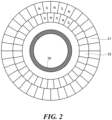
- an absolute magnetic encoder for detecting the absolute angle a well-known configuration includes annular magnetic tracks arranged concentrically around a rotary shaft and having magnetic poles alternately arranged at equal intervals in the circumferential direction, and a magnetism detection element is arranged opposite to the magnetic track in the rotary shaft direction, referring to, for example, Patent Documents 1-3.
- EP2579002 A1 discloses a magnetic encoder with tracks that are configured such that the magnetic patterns thereof acting on position of the corresponding sensor are, under the interference of magnetism of the plural rows of magnetic encoder tracks, detected by the corresponding sensor as an equal pitch magnetic pattern.
- a plurality of magnetism detection elements arranged corresponding to each magnetic track often have the same performance in sensitivity, and from the viewpoint of improving detection accuracy, it is preferable that the magnetic flux density (maximum magnetic flux density) of each magnetic track to be detected by the magnetism detection element be almost the same.
- the absolute magnetic encoder includes a first magnetic track, a second magnetic track, a magnetic sensor unit, a first detected face, a second detected face, and level difference.
- the first magnetic track is constituted with an annular multipolar magnet in which magnetic poles are alternately arranged at equal intervals in the circumferential direction.
- the second magnetic track is constituted with an annular multipolar magnet in which magnetic poles, the number of which being different from that of the first magnetic track, are alternately arranged at equal intervals in the circumferential direction.
- the second magnetic track is provided concentrically with the first magnetic track inside the first magnetic track in the radial direction.
- the magnetic sensor unit is provided so as to oppose the first magnetic track in the axial direction of the first magnetic track and the second magnetic track in the axial direction of the second magnetic track and to be relatively movable to each of the first and the second magnetic tracks.
- the magnetic sensor unit respectively detects the magnetic flux density of the first magnetic track and the magnetic flux density of the second magnetic track.
- the first detected face is a magnetic pole face of the first magnetic track opposite to the magnetic sensor unit.
- the second detected face is a magnetic pole face of the second magnetic track opposite to the magnetic sensor unit.
- the level difference is set based on the difference between the maximum magnetic flux density of the first magnetic track and the maximum magnetic flux density of the second magnetic track which are detected by the magnetic sensor unit, and the level difference is constituted in the axial direction between the first detected face and the second detected face.
- the above-mentioned absolute magnetic encoder employs a configuration in which an end portion on the inner diameter side of the first magnetic track and an end portion on the outer diameter side of the second magnetic track are arranged in a contact condition.
- allowable range of the change in the relative position of the first and the second magnetic tracks and the magnetic sensor increases when axial runout occurs on the rotary shaft for relatively moving the first and the second magnetic tracks and the magnetic sensor unit, or when positional runout occurs in the mounting positions of the magnetic tracks and the magnetic sensor unit.
- There is no gap between the first magnetic track and the second magnetic track so that the radial width of each magnetic track is increased.
- the first magnetic track and the second magnetic track can be respectively constituted with a separated multipolar magnet made of magnetic rubber material.
- the first detected face and the second detected face are configured.
- the first magnetic track and the second magnetic track are assembled integrally, so that the magnetic poles of the magnetic track formed in advance do not interfere with the magnetization treatment for the subsequent magnetic track formation. As a result, manufacturing is facilitated.
- the dimension of the level difference can be set in such a manner that the difference between the maximum magnetic flux density of the first magnetic track and the maximum magnetic flux density of the second magnetic track is within a predetermined range.
- an end portion on the inner diameter side of the first magnetic track can be provided so as to come into contact with an end portion on the outer diameter side of the second magnetic track.
- the first magnetic track and the second magnetic track can be separately constituted with a multipolar magnet made of magnetic rubber material; the first detected face and the second detected face can be configured in such a manner that the first magnetic track and the second magnetic track are supported by a single support member.
- the dimension of the level difference (positional difference) between the detected faces can be set in such a manner that the magnitudes of the magnetic flux densities of both magnetic tracks to be detected by the magnetic sensor unit are set to be almost the same.
- the dimension of the level difference can be set based on the difference between an air gap "x1" relative to the first detected face and an air gap "x2" relative to the second detected face in which the difference between the maximum magnetic flux density of the first magnetic track and the maximum magnetic flux density of the second magnetic track is within a predetermined range.
- the total number of each pole of the first magnetic track can be "m" and the total number of each pole of the second magnetic track can be (m-2).
- the difference between the size of one magnetic pole included in the first magnetic track and the size of one magnetic pole included in the second magnetic track is made small, so that the positional difference between the first detected face and the second detected face in the axial direction is reduced.
- the air gap between the detected face and the magnetic sensor unit is set to be small.
- the method for setting the absolute magnetic encoder in the embodiment of the present invention is a setting method of the absolute magnetic encoder including the first magnetic track constituted with the annular multipolar magnet in which the magnetic poles are alternately provided at equal intervals in the circumferential direction, the second magnetic track constituted with the annular multipolar magnet in which the magnetic poles are alternately provided at equal intervals in the circumferential direction, the number of the poles being different from that of the first magnetic track, the second magnetic track being provided concentrically with the first magnetic track inside the first magnetic track in the radial direction, and the magnetic sensor unit to respectively detect the magnetic flux density of the first magnetic track and the magnetic flux density of the second magnetic track, the magnetic sensor being provided opposite to the first magnetic track in the axial direction of the first magnetic track and opposite to the second magnetic track in the axial direction of the second magnetic track, the magnetic sensor unit being provided so as to be relatively movable to each of the first magnetic track and the second magnetic track.
- the method includes a step of obtaining the maximum magnetic flux density of the first magnetic track which is detected by position of the magnetic sensor unit, a step of obtaining the maximum magnetic flux density of the second magnetic track which is detected by position of the magnetic sensor unit, and a step of setting the level difference in the axial direction between the first detected face of the first magnetic track and the second detected face of the second magnetic track based on the difference between the obtained maximum magnetic flux density of the first magnetic track and the obtained maximum magnetic flux density of the second magnetic track, the first detected face being the magnetic pole face of the first magnetic track opposite to the magnetic sensor unit, the second detected face being the magnetic pole face of the second magnetic track opposite to the magnetic sensor unit.
- the dimension of the level difference can be set in such a manner that the difference between the maximum magnetic flux density of the first magnetic track and the maximum magnetic flux density of the second magnetic track is within a predetermined range.
- the dimension of the level difference can be set based on the difference between the air gap "x1" relative to the first detected face and the air gap "x2" relative to the second detected face in which the difference between the maximum magnetic flux density of the first magnetic track and the maximum magnetic flux density of the second magnetic track is within a predetermined range.
- the detection accuracy is further improved in the absolute magnetic encoder configured such that a plurality of annular magnetic tracks are arranged concentrically around the rotary shaft and the magnetism detection element is arranged opposite to the rotary shaft direction.
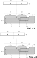
- FIG. 1A is a plan view diagrammatically illustrating the example of the absolute magnetic encoder in one embodiment of the present invention.
- FIG. 1B is a longitudinal sectional view diagrammatically illustrating the example of the absolute magnetic encoder in the embodiment of the present invention.
- FIG. 1C is a longitudinal sectional view along the diametrical direction in FIG. 1A .
- the first magnetic track 21 is configured such that the annular region on one face side of the core member 10 is magnetized as a multipolar magnet in which the N poles and the S poles are alternately arranged at equal intervals in the circumferential direction, as mentioned above.
- the magnetic flux density of the first detected face 21a and the magnetic flux density of the second detected face 22a are expressed by the following equation (1) using the residual magnetic flux density Bo, the total pole number "n”, the air gap "x" between the detected face and the magnetic sensor unit, and the diameter "d” in which the magnetism detection element of the magnetic sensor unit 30 is disposed.
- B Boexp ⁇ n ⁇ x / d
- the dimension L of the level difference 23, i.e., the positional difference, in position in the axial direction between the first detected face 21a and the second detected face 22a is set based on the difference of the air gap "x" in which the difference between the magnetic flux density (the maximum magnetic flux density) of the first detected face 21a and the magnetic flux density (the maximum magnetic flux density) of the second detected face 22a which are calculated by the equation (1) is within a predetermined range.
- the range specified in advance for the difference D between the maximum magnetic flux density of the first detected face 21a and the maximum magnetic flux density of the second detected face 22a is supposed to be, for example, the maximum value D H or less.
- the specific value of the maximum value D H is not generalized because it depends on the performance such as sensitivity of the magnetic sensor unit 30, the size of the air gap, the magnetization amount of both magnetic tracks 21, 22, etc., but a value in which the magnitudes of the maximum magnetic flux densities of magnetic tracks 21, 22 to be detected in the magnetic sensor unit 30 practically accord can be appropriately set.
- the magnitudes of the maximum magnetic flux densities of two magnetic tracks 21, 22 to be detected in the magnetic sensor unit 30 are set almost the same by setting the range of the dimension L of the level difference 23, i.e., the positional difference, along the axial direction between the first detected face 21a and the second detected face 22a.
- the absolute magnetic encoder 1 of the present embodiment since there is no gap between the first magnetic track 21 and the second magnetic track 22, the radial width of each magnetic track is increased. Therefore, for example, as illustrated in FIG. 4B , even if axial runout occurs such that the rotary shaft moves from the magnetic sensor unit to the shaft side (right direction in the figure), the magnetism detection element 31 and the magnetism detection element 32 are located above the corresponding first magnetic track 21 and the second magnetic track 22. That is, the axial runout resistance is further improved compared with a configuration in which a gap is provided between the first magnetic track 21 and the second magnetic track 22. Further, when using a magnetic sensor unit in which a plurality of magnetism detection elements are integrally disposed, as a result of being able to increase the application flexibility of the magnetic sensor unit, a smaller magnetic sensor unit is able to be adopted, for example.
- a ring-like member 14 on which the second magnetic track 22 is supported is connected to the core 10 on which the first magnetic track 21 is supported as a preferred embodiment.
- the first magnetic track 21 and the second magnetic track 22 are required to be arranged in such a manner that the first detected face 21a and the second detected face 22a are arranged with the dimension L of the level difference 23, i.e., the positional difference, as mentioned above, and the first magnetic track 21 and the second magnetic track 22 are not have to be supported by separate support members.
- the detection accuracy is further improved in the absolute magnetic encoder having a configuration in which a plurality of annular magnetic tracks arranged concentrically around the rotary shaft and the magnetism detection elements are arranged opposite in the rotary shaft direction.
Landscapes
- Physics & Mathematics (AREA)
- General Physics & Mathematics (AREA)
- Transmission And Conversion Of Sensor Element Output (AREA)
Claims (11)
- Encodeur magnétique absolu (1), comprenant :une première piste magnétique (21) comprenant un aimant multipolaire annulaire, dans lequel des pôles magnétiques sont fournis en alternances à des intervalles égaux dans la direction circonférentielle ;une deuxième piste magnétique (22) comprenant un aimant multipolaire annulaire, dans lequel des pôles magnétiques sont fournis en alternance à des intervalles égaux dans la direction circonférentielle, le nombre de pôles magnétiques de la deuxième piste magnétique (22) étant différent du nombre de pôles magnétiques de la première piste magnétique (21), la deuxième piste magnétique (22) étant fournie de manière concentrique avec la première piste magnétique (21) à l'intérieur de la première piste magnétique (21) dans la direction radiale ;une unité de capteur magnétique (30) pour détecter respectivement une densité de flux magnétique de la première piste magnétique (21) et une densité de flux magnétique de la deuxième piste magnétique (22), l'unité de capteur magnétique (30) étant fournie à l'opposé de la première piste magnétique (21) dans la direction axiale de la première piste magnétique (21) et à l'opposé de la deuxième piste magnétique (22) dans la direction axiale de la deuxième piste magnétique (22), l'unité de capteur magnétique (30) étant fournie de manière relativement mobile vers la première piste magnétique (21) et la deuxième piste magnétique (22) respectivement ;une première face détectée (21a) qui est une face de pôle magnétique de la première piste magnétique (21) à l'opposé de l'unité de capteur magnétique (30) ; etune deuxième face détectée (22a) qui est une face de pôle magnétique de la deuxième piste magnétique (22) à l'opposé de l'unité de capteur magnétique (30) ;dans lequel la première face détectée (21a) et la deuxième face détectée (22a) sont fournies avec une différence de niveau (23) dans la direction axiale,caractérisé en ce quela différence de niveau (23) est réglée sur la base d'une différence entre une densité de flux magnétique maximale de la première piste magnétique (21) et une densité de flux magnétique maximale de la deuxième piste magnétique (22) qui sont détectées par l'unité de capteur magnétique (30).
- Encodeur magnétique absolu (1) selon la revendication 1, dans lequel une dimension (L) de la différence de niveau (23) est réglée de telle manière que la différence entre la densité de flux magnétique maximale de la première piste magnétique (21) et la densité de flux magnétique maximale de la deuxième piste magnétique (22) se situe dans une plage prédéterminée.
- Encodeur magnétique absolu (1) selon la revendication 1 ou 2, dans lequel une partie d'extrémité sur un côté de diamètre intérieur de la première piste magnétique (21) et une partie d'extrémité sur un côté de diamètre extérieur de la deuxième piste magnétique (22) viennent en contact.
- Encodeur magnétique absolu (1) selon la revendication 1 ou 2, dans lequel la première piste magnétique (21) et la deuxième piste magnétique (22) comprennent respectivement un aimant multipolaire fait d'un matériau en caoutchouc magnétique, la première face détectée (21a) et la deuxième face détectée (22a) sont configurées de telle manière que la première piste magnétique (21) et la deuxième piste magnétique (22) sont supportées par un unique élément de support.
- Encodeur magnétique absolu (1) selon la revendication 1 ou 2, dans lequel la densité de flux magnétique maximale de la première piste magnétique (21) et la densité de flux magnétique maximale de la deuxième piste magnétique (22) sont calculées sur la base d'une équation (1),

- Encodeur magnétique absolu (1) selon la revendication 5, dans lequel la dimension (L) de la différence de niveau (23) est définie sur la base d'une différence entre un entrefer « x1 » par rapport à la première face détectée (21a) et un entrefer « x2 » par rapport à la deuxième face détectée (22a), où la différence entre la densité de flux magnétique maximale de la première piste magnétique (21) et la densité de flux magnétique maximale de la deuxième piste magnétique (22) se situe dans une plage prédéterminée.
- Encodeur magnétique absolu (1) selon la revendication 1 ou 2, dans lequel un nombre total de chaque type de pôle de la première piste magnétique (21) est « m » et un nombre total de chaque type de pôle de la deuxième piste magnétique (22) est (m-2).
- Procédé de réglage d'un encodeur magnétique absolu (1), dans lequel l'encodeur magnétique absolu (1) comprend une première piste magnétique (21) comprenant un aimant multipolaire annulaire, dans lequel des pôles magnétiques sont fournis en alternance à des intervalles égaux dans la direction circonférentielle, une deuxième piste magnétique (22) comprenant un aimant multipolaire annulaire, dans lequel des pôles magnétiques sont fournis en alternance à des intervalles égaux dans la direction circonférentielle, le nombre de pôles magnétique de la deuxième piste magnétique (22) étant différent du nombre de pôles magnétiques de la première piste magnétique (21), la deuxième piste magnétique (22) étant fournie de manière concentrique avec la première piste magnétique (21) à l'intérieur de la première piste magnétique (21) dans la direction radiale, et une unité de capteur magnétique (30) pour détecter chacune de la densité de flux magnétique de la première piste magnétique (21) et la densité de flux magnétique de la deuxième piste magnétique (22), l'unité de capteur magnétique (30) étant fournie à l'opposé de la première piste magnétique (21) dans la direction axiale de la première piste magnétique (21) et à l'opposé de la deuxième piste magnétique (22) dans la direction axiale de la deuxième piste magnétique (22), l'unité de capteur magnétique (30) étant fournie de manière relativement mobile vers la première piste magnétique (21) et la deuxième piste magnétique (22) respectivement,caractérisé en ce que le procédé comprendune étape d'obtention de la densité de flux magnétique maximale de la première piste magnétique (21) qui est détectée par une position de l'unité de capteur magnétique (30),une étape d'obtention d'une densité de flux magnétique maximale de la deuxième piste magnétique (22) qui est détectée par une position de l'unité de capteur magnétique (22), etune étape de réglage d'une différence de niveau (23) dans la direction axiale entre la première face détectée (21a) de la première piste magnétique (21) et la deuxième face détectée (22a) de la deuxième piste magnétique (22) sur la base d'une différence entre une densité de flux magnétique maximale obtenue de la première piste magnétique (21) et une densité de flux magnétique maximale obtenue de la deuxième piste magnétique (22), la première face détectée (21a) étant une face de pôle magnétique de la première piste magnétique (21) à l'opposé de l'unité de capteur magnétique (30), la deuxième face détectée (22a) étant une face de pôle magnétique de la deuxième piste magnétique (22) à l'opposé de l'unité de capteur magnétique (30).
- Procédé de réglage d'un encodeur magnétique absolu (1) selon la revendication 8, dans lequel une dimension (L) de la différence de niveau (23) est réglée de telle manière qu'une différence entre la densité de flux magnétique maximale de la première piste magnétique (21) et la densité de flux magnétique maximale de la deuxième piste magnétique (22) se situe dans une plage prédéterminée.
- Procédé de définition d'un encodeur magnétique absolu (1) selon la revendication 8 ou 9, dans lequel la densité de flux magnétique maximale de la première piste magnétique (21) et la densité de flux magnétique maximale de la deuxième piste magnétique (22) sont calculées sur la base d'une équation (2),

- Procédé de définition d'un encodeur magnétique absolu (1) selon la revendication 10, dans lequel la dimension (L) de la différence de niveau (23) est réglée sur la base d'une différence entre un entrefer « x1 » par rapport à la première face détectée (21a) et un entrefer « x2 » par rapport à la deuxième face détectée (22a), où la différence entre la densité de flux magnétique maximale de la première piste magnétique (21) et la densité de flux magnétique maximale de la deuxième piste magnétique (22) se situe dans une plage prédéterminée.
Applications Claiming Priority (2)
| Application Number | Priority Date | Filing Date | Title |
|---|---|---|---|
| JP2021127847 | 2021-08-03 | ||
| JP2022122842A JP2023022828A (ja) | 2021-08-03 | 2022-08-01 | アブソリュート磁気エンコーダ及びその設計方法 |
Publications (2)
| Publication Number | Publication Date |
|---|---|
| EP4130681A1 EP4130681A1 (fr) | 2023-02-08 |
| EP4130681B1 true EP4130681B1 (fr) | 2023-12-27 |
Family
ID=83283509
Family Applications (1)
| Application Number | Title | Priority Date | Filing Date |
|---|---|---|---|
| EP22188512.2A Active EP4130681B1 (fr) | 2021-08-03 | 2022-08-03 | Codeur magnétique absolu et procédé de réglage |
Country Status (1)
| Country | Link |
|---|---|
| EP (1) | EP4130681B1 (fr) |
Families Citing this family (1)
| Publication number | Priority date | Publication date | Assignee | Title |
|---|---|---|---|---|
| CN120213096A (zh) * | 2025-04-28 | 2025-06-27 | 中电海康集团有限公司 | 绝对位置磁编码器 |
Family Cites Families (6)
| Publication number | Priority date | Publication date | Assignee | Title |
|---|---|---|---|---|
| JP3200361B2 (ja) | 1996-03-19 | 2001-08-20 | 矢崎総業株式会社 | 回転センサ |
| JPH10170212A (ja) | 1996-12-06 | 1998-06-26 | Mitsutoyo Corp | 絶対値型磁気式変位検出装置 |
| FR2930637B1 (fr) | 2008-04-23 | 2010-06-18 | Roulements Soc Nouvelle | Montage d'un systeme de determination de position angulaire comprenant deux aimants multipolaires |
| JP5314556B2 (ja) | 2009-10-05 | 2013-10-16 | Ntn株式会社 | 磁気エンコーダおよびその製造方法、回転検出装置 |
| JP5379748B2 (ja) * | 2010-06-03 | 2013-12-25 | Ntn株式会社 | 磁気エンコーダ |
| JP5973278B2 (ja) * | 2012-08-16 | 2016-08-23 | Ntn株式会社 | 磁気エンコーダの着磁装置 |
-
2022
- 2022-08-03 EP EP22188512.2A patent/EP4130681B1/fr active Active
Also Published As
| Publication number | Publication date |
|---|---|
| EP4130681A1 (fr) | 2023-02-08 |
Similar Documents
| Publication | Publication Date | Title |
|---|---|---|
| EP1447579B1 (fr) | Palier a roulement equipe d'un detecteur et dispositif de detection d'un mode de rotation | |
| EP2579002A1 (fr) | Encodeur magnétique | |
| US5583431A (en) | Hub unit with rotation speed sensor | |
| US11536591B2 (en) | Magnetic encoder | |
| EP4130681B1 (fr) | Codeur magnétique absolu et procédé de réglage | |
| EP3431932B1 (fr) | Aimants annulaires pour estimation de position de rotor | |
| US12092163B2 (en) | Method for mounting a sensor bearing unit, and sensor bearing unit adapted to such a method | |
| JP2023022828A (ja) | アブソリュート磁気エンコーダ及びその設計方法 | |
| CN113607194B (zh) | 磁编码器 | |
| US20210286027A1 (en) | Magnetic detection device | |
| JP2006090831A (ja) | 回転センサ付軸受 | |
| US6003375A (en) | Hub unit with rotation speed sensor | |
| JP2023174372A (ja) | アブソリュート磁気エンコーダ | |
| JP2023174371A (ja) | アブソリュート磁気エンコーダ | |
| US11971071B2 (en) | Sensor bearing unit and associated apparatus | |
| US20250035165A1 (en) | Sensor bearing assembly | |
| US11378131B2 (en) | Method for manufacturing a sensor bearing unit | |
| JP2004258028A (ja) | 回転パラメータをコード化する装置、これを有するころがり軸受そして電動モータ | |
| US20240110599A1 (en) | Sensor bearing unit and associated apparatus | |
| JP4840246B2 (ja) | センサ付き転がり軸受装置の製造方法 | |
| JP2007057236A (ja) | 多回転絶対角度検出機能付軸受 | |
| JP2023017429A (ja) | 回転機構 | |
| JP2005248999A (ja) | 回転センサ付軸受 | |
| JPH08194008A (ja) | 回転速度検出装置付転がり軸受ユニット |
Legal Events
| Date | Code | Title | Description |
|---|---|---|---|
| PUAI | Public reference made under article 153(3) epc to a published international application that has entered the european phase |
Free format text: ORIGINAL CODE: 0009012 |
|
| STAA | Information on the status of an ep patent application or granted ep patent |
Free format text: STATUS: THE APPLICATION HAS BEEN PUBLISHED |
|
| AK | Designated contracting states |
Kind code of ref document: A1 Designated state(s): AL AT BE BG CH CY CZ DE DK EE ES FI FR GB GR HR HU IE IS IT LI LT LU LV MC MK MT NL NO PL PT RO RS SE SI SK SM TR |
|
| STAA | Information on the status of an ep patent application or granted ep patent |
Free format text: STATUS: REQUEST FOR EXAMINATION WAS MADE |
|
| 17P | Request for examination filed |
Effective date: 20230321 |
|
| RBV | Designated contracting states (corrected) |
Designated state(s): AL AT BE BG CH CY CZ DE DK EE ES FI FR GB GR HR HU IE IS IT LI LT LU LV MC MK MT NL NO PL PT RO RS SE SI SK SM TR |
|
| GRAP | Despatch of communication of intention to grant a patent |
Free format text: ORIGINAL CODE: EPIDOSNIGR1 |
|
| STAA | Information on the status of an ep patent application or granted ep patent |
Free format text: STATUS: GRANT OF PATENT IS INTENDED |
|
| INTG | Intention to grant announced |
Effective date: 20230721 |
|
| RIC1 | Information provided on ipc code assigned before grant |
Ipc: G01D 5/12 20060101AFI20230707BHEP |
|
| GRAS | Grant fee paid |
Free format text: ORIGINAL CODE: EPIDOSNIGR3 |
|
| GRAA | (expected) grant |
Free format text: ORIGINAL CODE: 0009210 |
|
| STAA | Information on the status of an ep patent application or granted ep patent |
Free format text: STATUS: THE PATENT HAS BEEN GRANTED |
|
| AK | Designated contracting states |
Kind code of ref document: B1 Designated state(s): AL AT BE BG CH CY CZ DE DK EE ES FI FR GB GR HR HU IE IS IT LI LT LU LV MC MK MT NL NO PL PT RO RS SE SI SK SM TR |
|
| REG | Reference to a national code |
Ref country code: GB Ref legal event code: FG4D |
|
| REG | Reference to a national code |
Ref country code: CH Ref legal event code: EP |
|
| REG | Reference to a national code |
Ref country code: DE Ref legal event code: R096 Ref document number: 602022001473 Country of ref document: DE |
|
| REG | Reference to a national code |
Ref country code: IE Ref legal event code: FG4D |
|
| PG25 | Lapsed in a contracting state [announced via postgrant information from national office to epo] |
Ref country code: GR Free format text: LAPSE BECAUSE OF FAILURE TO SUBMIT A TRANSLATION OF THE DESCRIPTION OR TO PAY THE FEE WITHIN THE PRESCRIBED TIME-LIMIT Effective date: 20240328 |
|
| REG | Reference to a national code |
Ref country code: LT Ref legal event code: MG9D |
|
| PG25 | Lapsed in a contracting state [announced via postgrant information from national office to epo] |
Ref country code: LT Free format text: LAPSE BECAUSE OF FAILURE TO SUBMIT A TRANSLATION OF THE DESCRIPTION OR TO PAY THE FEE WITHIN THE PRESCRIBED TIME-LIMIT Effective date: 20231227 |
|
| PG25 | Lapsed in a contracting state [announced via postgrant information from national office to epo] |
Ref country code: ES Free format text: LAPSE BECAUSE OF FAILURE TO SUBMIT A TRANSLATION OF THE DESCRIPTION OR TO PAY THE FEE WITHIN THE PRESCRIBED TIME-LIMIT Effective date: 20231227 |
|
| PG25 | Lapsed in a contracting state [announced via postgrant information from national office to epo] |
Ref country code: LT Free format text: LAPSE BECAUSE OF FAILURE TO SUBMIT A TRANSLATION OF THE DESCRIPTION OR TO PAY THE FEE WITHIN THE PRESCRIBED TIME-LIMIT Effective date: 20231227 Ref country code: GR Free format text: LAPSE BECAUSE OF FAILURE TO SUBMIT A TRANSLATION OF THE DESCRIPTION OR TO PAY THE FEE WITHIN THE PRESCRIBED TIME-LIMIT Effective date: 20240328 Ref country code: FI Free format text: LAPSE BECAUSE OF FAILURE TO SUBMIT A TRANSLATION OF THE DESCRIPTION OR TO PAY THE FEE WITHIN THE PRESCRIBED TIME-LIMIT Effective date: 20231227 Ref country code: ES Free format text: LAPSE BECAUSE OF FAILURE TO SUBMIT A TRANSLATION OF THE DESCRIPTION OR TO PAY THE FEE WITHIN THE PRESCRIBED TIME-LIMIT Effective date: 20231227 Ref country code: BG Free format text: LAPSE BECAUSE OF FAILURE TO SUBMIT A TRANSLATION OF THE DESCRIPTION OR TO PAY THE FEE WITHIN THE PRESCRIBED TIME-LIMIT Effective date: 20240327 |
|
| REG | Reference to a national code |
Ref country code: NL Ref legal event code: MP Effective date: 20231227 |
|
| REG | Reference to a national code |
Ref country code: AT Ref legal event code: MK05 Ref document number: 1644920 Country of ref document: AT Kind code of ref document: T Effective date: 20231227 |
|
| PG25 | Lapsed in a contracting state [announced via postgrant information from national office to epo] |
Ref country code: NL Free format text: LAPSE BECAUSE OF FAILURE TO SUBMIT A TRANSLATION OF THE DESCRIPTION OR TO PAY THE FEE WITHIN THE PRESCRIBED TIME-LIMIT Effective date: 20231227 |
|
| PG25 | Lapsed in a contracting state [announced via postgrant information from national office to epo] |
Ref country code: SE Free format text: LAPSE BECAUSE OF FAILURE TO SUBMIT A TRANSLATION OF THE DESCRIPTION OR TO PAY THE FEE WITHIN THE PRESCRIBED TIME-LIMIT Effective date: 20231227 Ref country code: RS Free format text: LAPSE BECAUSE OF FAILURE TO SUBMIT A TRANSLATION OF THE DESCRIPTION OR TO PAY THE FEE WITHIN THE PRESCRIBED TIME-LIMIT Effective date: 20231227 Ref country code: NO Free format text: LAPSE BECAUSE OF FAILURE TO SUBMIT A TRANSLATION OF THE DESCRIPTION OR TO PAY THE FEE WITHIN THE PRESCRIBED TIME-LIMIT Effective date: 20240327 Ref country code: NL Free format text: LAPSE BECAUSE OF FAILURE TO SUBMIT A TRANSLATION OF THE DESCRIPTION OR TO PAY THE FEE WITHIN THE PRESCRIBED TIME-LIMIT Effective date: 20231227 Ref country code: LV Free format text: LAPSE BECAUSE OF FAILURE TO SUBMIT A TRANSLATION OF THE DESCRIPTION OR TO PAY THE FEE WITHIN THE PRESCRIBED TIME-LIMIT Effective date: 20231227 Ref country code: HR Free format text: LAPSE BECAUSE OF FAILURE TO SUBMIT A TRANSLATION OF THE DESCRIPTION OR TO PAY THE FEE WITHIN THE PRESCRIBED TIME-LIMIT Effective date: 20231227 |
|
| PG25 | Lapsed in a contracting state [announced via postgrant information from national office to epo] |
Ref country code: IS Free format text: LAPSE BECAUSE OF FAILURE TO SUBMIT A TRANSLATION OF THE DESCRIPTION OR TO PAY THE FEE WITHIN THE PRESCRIBED TIME-LIMIT Effective date: 20240427 |
|
| PG25 | Lapsed in a contracting state [announced via postgrant information from national office to epo] |
Ref country code: CZ Free format text: LAPSE BECAUSE OF FAILURE TO SUBMIT A TRANSLATION OF THE DESCRIPTION OR TO PAY THE FEE WITHIN THE PRESCRIBED TIME-LIMIT Effective date: 20231227 Ref country code: AT Free format text: LAPSE BECAUSE OF FAILURE TO SUBMIT A TRANSLATION OF THE DESCRIPTION OR TO PAY THE FEE WITHIN THE PRESCRIBED TIME-LIMIT Effective date: 20231227 |
|
| PG25 | Lapsed in a contracting state [announced via postgrant information from national office to epo] |
Ref country code: SK Free format text: LAPSE BECAUSE OF FAILURE TO SUBMIT A TRANSLATION OF THE DESCRIPTION OR TO PAY THE FEE WITHIN THE PRESCRIBED TIME-LIMIT Effective date: 20231227 |
|
| PG25 | Lapsed in a contracting state [announced via postgrant information from national office to epo] |
Ref country code: SM Free format text: LAPSE BECAUSE OF FAILURE TO SUBMIT A TRANSLATION OF THE DESCRIPTION OR TO PAY THE FEE WITHIN THE PRESCRIBED TIME-LIMIT Effective date: 20231227 Ref country code: SK Free format text: LAPSE BECAUSE OF FAILURE TO SUBMIT A TRANSLATION OF THE DESCRIPTION OR TO PAY THE FEE WITHIN THE PRESCRIBED TIME-LIMIT Effective date: 20231227 Ref country code: RO Free format text: LAPSE BECAUSE OF FAILURE TO SUBMIT A TRANSLATION OF THE DESCRIPTION OR TO PAY THE FEE WITHIN THE PRESCRIBED TIME-LIMIT Effective date: 20231227 Ref country code: IT Free format text: LAPSE BECAUSE OF FAILURE TO SUBMIT A TRANSLATION OF THE DESCRIPTION OR TO PAY THE FEE WITHIN THE PRESCRIBED TIME-LIMIT Effective date: 20231227 Ref country code: IS Free format text: LAPSE BECAUSE OF FAILURE TO SUBMIT A TRANSLATION OF THE DESCRIPTION OR TO PAY THE FEE WITHIN THE PRESCRIBED TIME-LIMIT Effective date: 20240427 Ref country code: EE Free format text: LAPSE BECAUSE OF FAILURE TO SUBMIT A TRANSLATION OF THE DESCRIPTION OR TO PAY THE FEE WITHIN THE PRESCRIBED TIME-LIMIT Effective date: 20231227 Ref country code: CZ Free format text: LAPSE BECAUSE OF FAILURE TO SUBMIT A TRANSLATION OF THE DESCRIPTION OR TO PAY THE FEE WITHIN THE PRESCRIBED TIME-LIMIT Effective date: 20231227 Ref country code: AT Free format text: LAPSE BECAUSE OF FAILURE TO SUBMIT A TRANSLATION OF THE DESCRIPTION OR TO PAY THE FEE WITHIN THE PRESCRIBED TIME-LIMIT Effective date: 20231227 |
|
| PG25 | Lapsed in a contracting state [announced via postgrant information from national office to epo] |
Ref country code: PT Free format text: LAPSE BECAUSE OF FAILURE TO SUBMIT A TRANSLATION OF THE DESCRIPTION OR TO PAY THE FEE WITHIN THE PRESCRIBED TIME-LIMIT Effective date: 20240429 Ref country code: PL Free format text: LAPSE BECAUSE OF FAILURE TO SUBMIT A TRANSLATION OF THE DESCRIPTION OR TO PAY THE FEE WITHIN THE PRESCRIBED TIME-LIMIT Effective date: 20231227 |
|
| REG | Reference to a national code |
Ref country code: DE Ref legal event code: R097 Ref document number: 602022001473 Country of ref document: DE |
|
| PG25 | Lapsed in a contracting state [announced via postgrant information from national office to epo] |
Ref country code: DK Free format text: LAPSE BECAUSE OF FAILURE TO SUBMIT A TRANSLATION OF THE DESCRIPTION OR TO PAY THE FEE WITHIN THE PRESCRIBED TIME-LIMIT Effective date: 20231227 |
|
| PG25 | Lapsed in a contracting state [announced via postgrant information from national office to epo] |
Ref country code: DK Free format text: LAPSE BECAUSE OF FAILURE TO SUBMIT A TRANSLATION OF THE DESCRIPTION OR TO PAY THE FEE WITHIN THE PRESCRIBED TIME-LIMIT Effective date: 20231227 |
|
| PLBE | No opposition filed within time limit |
Free format text: ORIGINAL CODE: 0009261 |
|
| STAA | Information on the status of an ep patent application or granted ep patent |
Free format text: STATUS: NO OPPOSITION FILED WITHIN TIME LIMIT |
|
| 26N | No opposition filed |
Effective date: 20240930 |
|
| PG25 | Lapsed in a contracting state [announced via postgrant information from national office to epo] |
Ref country code: LU Free format text: LAPSE BECAUSE OF NON-PAYMENT OF DUE FEES Effective date: 20240803 |
|
| PG25 | Lapsed in a contracting state [announced via postgrant information from national office to epo] |
Ref country code: SI Free format text: LAPSE BECAUSE OF FAILURE TO SUBMIT A TRANSLATION OF THE DESCRIPTION OR TO PAY THE FEE WITHIN THE PRESCRIBED TIME-LIMIT Effective date: 20231227 Ref country code: MC Free format text: LAPSE BECAUSE OF FAILURE TO SUBMIT A TRANSLATION OF THE DESCRIPTION OR TO PAY THE FEE WITHIN THE PRESCRIBED TIME-LIMIT Effective date: 20231227 |
|
| REG | Reference to a national code |
Ref country code: BE Ref legal event code: MM Effective date: 20240831 |
|
| PG25 | Lapsed in a contracting state [announced via postgrant information from national office to epo] |
Ref country code: BE Free format text: LAPSE BECAUSE OF NON-PAYMENT OF DUE FEES Effective date: 20240831 |
|
| PG25 | Lapsed in a contracting state [announced via postgrant information from national office to epo] |
Ref country code: FR Free format text: LAPSE BECAUSE OF NON-PAYMENT OF DUE FEES Effective date: 20240831 |
|
| PG25 | Lapsed in a contracting state [announced via postgrant information from national office to epo] |
Ref country code: IE Free format text: LAPSE BECAUSE OF NON-PAYMENT OF DUE FEES Effective date: 20240803 |
|
| PGFP | Annual fee paid to national office [announced via postgrant information from national office to epo] |
Ref country code: DE Payment date: 20250829 Year of fee payment: 4 |
|
| PG25 | Lapsed in a contracting state [announced via postgrant information from national office to epo] |
Ref country code: CY Free format text: LAPSE BECAUSE OF FAILURE TO SUBMIT A TRANSLATION OF THE DESCRIPTION OR TO PAY THE FEE WITHIN THE PRESCRIBED TIME-LIMIT; INVALID AB INITIO Effective date: 20220803 |
|
| PG25 | Lapsed in a contracting state [announced via postgrant information from national office to epo] |
Ref country code: HU Free format text: LAPSE BECAUSE OF FAILURE TO SUBMIT A TRANSLATION OF THE DESCRIPTION OR TO PAY THE FEE WITHIN THE PRESCRIBED TIME-LIMIT; INVALID AB INITIO Effective date: 20220803 |
|
| REG | Reference to a national code |
Ref country code: CH Ref legal event code: H13 Free format text: ST27 STATUS EVENT CODE: U-0-0-H10-H13 (AS PROVIDED BY THE NATIONAL OFFICE) Effective date: 20260324 |
|
| PG25 | Lapsed in a contracting state [announced via postgrant information from national office to epo] |
Ref country code: CH Free format text: LAPSE BECAUSE OF NON-PAYMENT OF DUE FEES Effective date: 20250831 |