EP4131107A1 - Zerkleinerungssystem - Google Patents
Zerkleinerungssystem Download PDFInfo
- Publication number
- EP4131107A1 EP4131107A1 EP21779424.7A EP21779424A EP4131107A1 EP 4131107 A1 EP4131107 A1 EP 4131107A1 EP 21779424 A EP21779424 A EP 21779424A EP 4131107 A1 EP4131107 A1 EP 4131107A1
- Authority
- EP
- European Patent Office
- Prior art keywords
- information
- medium
- shredder
- unit
- scanner device
- Prior art date
- Legal status (The legal status is an assumption and is not a legal conclusion. Google has not performed a legal analysis and makes no representation as to the accuracy of the status listed.)
- Granted
Links
Images


Classifications
-
- B—PERFORMING OPERATIONS; TRANSPORTING
- B02—CRUSHING, PULVERISING, OR DISINTEGRATING; PREPARATORY TREATMENT OF GRAIN FOR MILLING
- B02C—CRUSHING, PULVERISING, OR DISINTEGRATING IN GENERAL; MILLING GRAIN
- B02C18/00—Disintegrating by knives or other cutting or tearing members which chop material into fragments
- B02C18/0007—Disintegrating by knives or other cutting or tearing members which chop material into fragments specially adapted for disintegrating documents
-
- B—PERFORMING OPERATIONS; TRANSPORTING
- B02—CRUSHING, PULVERISING, OR DISINTEGRATING; PREPARATORY TREATMENT OF GRAIN FOR MILLING
- B02C—CRUSHING, PULVERISING, OR DISINTEGRATING IN GENERAL; MILLING GRAIN
- B02C18/00—Disintegrating by knives or other cutting or tearing members which chop material into fragments
- B02C18/06—Disintegrating by knives or other cutting or tearing members which chop material into fragments with rotating knives
-
- B—PERFORMING OPERATIONS; TRANSPORTING
- B02—CRUSHING, PULVERISING, OR DISINTEGRATING; PREPARATORY TREATMENT OF GRAIN FOR MILLING
- B02C—CRUSHING, PULVERISING, OR DISINTEGRATING IN GENERAL; MILLING GRAIN
- B02C25/00—Control arrangements specially adapted for crushing or disintegrating
-
- G—PHYSICS
- G06—COMPUTING OR CALCULATING; COUNTING
- G06Q—INFORMATION AND COMMUNICATION TECHNOLOGY [ICT] SPECIALLY ADAPTED FOR ADMINISTRATIVE, COMMERCIAL, FINANCIAL, MANAGERIAL OR SUPERVISORY PURPOSES; SYSTEMS OR METHODS SPECIALLY ADAPTED FOR ADMINISTRATIVE, COMMERCIAL, FINANCIAL, MANAGERIAL OR SUPERVISORY PURPOSES, NOT OTHERWISE PROVIDED FOR
- G06Q10/00—Administration; Management
- G06Q10/10—Office automation; Time management
-
- H—ELECTRICITY
- H04—ELECTRIC COMMUNICATION TECHNIQUE
- H04N—PICTORIAL COMMUNICATION, e.g. TELEVISION
- H04N1/00—Scanning, transmission or reproduction of documents or the like, e.g. facsimile transmission; Details thereof
- H04N1/00127—Connection or combination of a still picture apparatus with another apparatus, e.g. for storage, processing or transmission of still picture signals or of information associated with a still picture
- H04N1/0032—Connection or combination of a still picture apparatus with another apparatus, e.g. for storage, processing or transmission of still picture signals or of information associated with a still picture with a medium handling apparatus, e.g. a sheet sorter
-
- H—ELECTRICITY
- H04—ELECTRIC COMMUNICATION TECHNIQUE
- H04N—PICTORIAL COMMUNICATION, e.g. TELEVISION
- H04N1/00—Scanning, transmission or reproduction of documents or the like, e.g. facsimile transmission; Details thereof
- H04N1/32—Circuits or arrangements for control or supervision between transmitter and receiver or between image input and image output device, e.g. between a still-image camera and its memory or between a still-image camera and a printer device
- H04N1/32101—Display, printing, storage or transmission of additional information, e.g. ID code, date and time or title
- H04N1/32106—Display, printing, storage or transmission of additional information, e.g. ID code, date and time or title separate from the image data, e.g. in a different computer file
- H04N1/32122—Display, printing, storage or transmission of additional information, e.g. ID code, date and time or title separate from the image data, e.g. in a different computer file in a separate device, e.g. in a memory or on a display separate from image data
-
- H—ELECTRICITY
- H04—ELECTRIC COMMUNICATION TECHNIQUE
- H04N—PICTORIAL COMMUNICATION, e.g. TELEVISION
- H04N2201/00—Indexing scheme relating to scanning, transmission or reproduction of documents or the like, and to details thereof
- H04N2201/0077—Types of the still picture apparatus
- H04N2201/0081—Image reader
-
- H—ELECTRICITY
- H04—ELECTRIC COMMUNICATION TECHNIQUE
- H04N—PICTORIAL COMMUNICATION, e.g. TELEVISION
- H04N2201/00—Indexing scheme relating to scanning, transmission or reproduction of documents or the like, and to details thereof
- H04N2201/32—Circuits or arrangements for control or supervision between transmitter and receiver or between image input and image output device, e.g. between a still-image camera and its memory or between a still-image camera and a printer device
- H04N2201/3201—Display, printing, storage or transmission of additional information, e.g. ID code, date and time or title
- H04N2201/3225—Display, printing, storage or transmission of additional information, e.g. ID code, date and time or title of data relating to an image, a page or a document
- H04N2201/3246—Display, printing, storage or transmission of additional information, e.g. ID code, date and time or title of data relating to an image, a page or a document of data relating to permitted access or usage, e.g. level of access or usage parameters for digital rights management [DRM] related to still images
-
- H—ELECTRICITY
- H04—ELECTRIC COMMUNICATION TECHNIQUE
- H04N—PICTORIAL COMMUNICATION, e.g. TELEVISION
- H04N2201/00—Indexing scheme relating to scanning, transmission or reproduction of documents or the like, and to details thereof
- H04N2201/32—Circuits or arrangements for control or supervision between transmitter and receiver or between image input and image output device, e.g. between a still-image camera and its memory or between a still-image camera and a printer device
- H04N2201/3285—Circuits or arrangements for control or supervision between transmitter and receiver or between image input and image output device, e.g. between a still-image camera and its memory or between a still-image camera and a printer device using picture signal storage, e.g. at transmitter
- H04N2201/3295—Deletion of stored data; Preventing such deletion
Definitions
- the present invention relates to a shredder system.
- Patent Document 1 There are a number of known conventional technologies related to shredders (see, for example, Patent Document 1).
- Patent Document 1 Japanese Unexamined Patent Application, Publication No. 2020-15027
- Patent Document 1 the conventional technologies including the technology disclosed in Patent Document 1 are insufficient, and it has been difficult to recover information fixed on a medium, which is an object to be shredded, after the medium has been fed into a shredder.
- the present invention was achieved in consideration of the above-described circumstances and an object thereof is to recover information fixed on a medium that has been fed into a shredder.
- a shredder system includes:
- the present service a service to which a shredder system (see FIG. 2 described below) according to the present invention is applied.
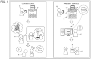
- FIG. 1 is a diagram illustrating an overview of an example of the present service that can be implemented through a shredder system according to an embodiment of the present invention, versus a conventional service.
- the present service is, for example, provided to a user K who works in an office or the like and who is in a position to manage a worker H.
- the present service is offered to recover information fixed on a medium P that should not be discarded due to its nature and to provide the recovered information to the user K, in a situation in which the worker H has shredded the medium P using a shredder without permission and the information fixed on the medium P has been destroyed.
- a shredder technology is used to shred the medium P, and thus make the confidential information indeterminable in order to prevent a non-related party from determining and appropriating the confidential information fixed on the medium P.
- the shredder technology allows for protection of privacy and prevention of information leakage by shredding the medium P, but is characterized by the fact that it is extremely difficult to recover the shredded medium P.
- a shredder is used for the purpose of protecting privacy or preventing information leakage, but not infrequently, is also intentionally used for the purpose of destroying information by someone who does not want the medium P to be recovered.
- the worker H may want to keep the medium P from coming to the attention of the user K, who is his/her supervisor.
- the following therefore considers a case where the worker H destroys the medium P on purpose.
- the medium P is treated as do-not-discard, because the medium P contains information about a contract with a client, and is therefore an important document to the office or the like (especially to the user K) .
- the worker H himself/herself has accidentally soiled the medium P.
- the worker H attempts to conceal his/her failure by destroying the medium P that proves his/her failure. That is, the worker H shreds the soiled medium P using a shredder that is not capable of information recovery to erase the medium P from existence. As a result of the medium P being thus destroyed, the information printed or otherwise fixed on the medium P is also destroyed.
- the user K has no way to notice that the medium P (i.e., the information fixed on the medium P) has been destroyed by the worker H. The medium P is therefore found to have been destroyed only when someone tries to reuse the information printed on the medium P at a later date, making the problem worse.
- the present service shown on the right side of FIG. 1 makes it possible to recover the information fixed on the medium P even after the medium P has been shredded using a shredder 1.
- a series of processes described below is performed.
- the medium P is scanned by a scanner device 11 provided within the shredder 1 before being shredded, and thus the information fixed on the medium P is read.
- the read information is transmitted to and stored in a server 2, which is described below with reference to FIG. 2 .
- the information fixed on the medium P that has been fed into the shredder 1 is saved in the server 2 before the medium P is shredded.
- the medium P is sent to a cutting unit 12 and shredded after the information fixed thereon has been read by the scanner device 11.
- the user K searches for and extracts the information of the medium P stored in the server 2 using a supervisor terminal 3. As described above, the user K can recover the information destroyed as a result of the worker H feeding the medium P into the shredder 1.
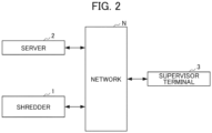
- FIG. 2 is a diagram illustrating a system configuration of the shredder system according to the embodiment of the present invention.
- the shredder system illustrated in FIG. 2 includes the shredder 1, the server 2, and the supervisor terminal 3.
- the shredder 1, the server 2, and the supervisor terminal 3 are connected to each other via a predetermined network N such as the Internet.
- a predetermined network N such as the Internet.
- No particular limitations are placed on the form of the network N, and examples of usable networks include Bluetooth (registered trademark), Wi-Fi, a local area network (LAN), and the Internet.
- the shredder 1 is, for example, installed in an office or the like and is operated by the worker H and others.
- the server 2 is, for example, an information processing device that is managed by a system administrator (not shown) under the supervision of the user K.
- the server 2 executes various processes while communicating with the shredder 1 and the supervisor terminal 3 as appropriate. No particular limitations are placed on who performs duties as the system administrator. For example, the user K himself/herself may perform the duties as the system administrator.
- the supervisor terminal 3 is an information processing device that is installed in the office or the like and operated by the user K.
- the supervisor terminal 3 includes, for example, a personal computer, a smartphone, or a tablet.
- FIG. 3 is a perspective view of an example of an external configuration of the shredder in the system configuration of the shredder system according to the embodiment of the present invention.
- the shredder 1 is placed on a plane (XY plane) formed by an X axis and a Y axis shown in FIG. 3 .
- an X axis direction is referred to below as a "length direction”
- a Y axis direction as a "width direction”
- an upward direction along a Z axis in FIG. 3 as an "up direction”
- a downward direction along the Z axis in FIG. 3 as a "down direction”.
- the shredder 1 includes the scanner device 11, the cutting unit 12, a housing unit 13, and a top panel unit 14.
- the top panel unit 14 is attached to an upper portion of the housing unit 13.
- the top panel unit 14 has a feed opening 15 for feeding a medium P.
- the scanner device 11 is provided within the housing unit 13 and is located right under the feed opening 15 provided in the top panel unit 14.
- the scanner device 11 reads information printed or otherwise fixed on a medium P and converts the read information into digital image data. Specifically, the scanner device 11 reads information fixed on a medium P with an automatic document feeder (not shown) transferring the medium P.
- the scanner device 11 then converts the read information into digital image data and outputs the converted information to an external destination.
- the cutting unit 12 is provided within the housing unit 13 and is located under the scanner device 11.
- the cutting unit 12 shreds the medium P that has been transferred thereto by the scanner device 11 (automatic document feeder) with fine blades.
- the medium P is fed into the shredder 1 through the feed opening 15, and then sent to the scanner device 11.
- the information fixed on the medium P is read by the scanner device 11, converted into digital image data, and then transmitted to the server 2. Thereafter, the medium P is transferred from the scanner device 11 to the cutting unit 12 and shredded.
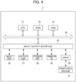
- FIG. 4 is a block diagram illustrating the hardware configuration of the server in the shredder system according to the embodiment of the present invention.
- the server 2 includes a central processing unit (CPU) 21, read only memory (ROM) 22, random access memory (RAM) 23, a bus 24, an input/output interface 25, an input unit 26, an output unit 27, a storage unit 28, a communication unit 29, and a drive 30.
- CPU central processing unit
- ROM read only memory
- RAM random access memory
- bus 24 an input/output interface 25
- input unit 26 an output unit 27
- storage unit 28 a communication unit 29, and a drive 30.
- the CPU 21 executes various processes in accordance with programs recorded in the ROM 22 or programs loaded from the storage unit 28 into the RAM 23. Data necessary for the CPU 21 to execute the various processes, for example, is also stored in the RAM 23 as appropriate.
- the CPU 21, the ROM 22, and the RAM 23 are connected to each other via the bus 24.
- the input/output interface 25 is also connected to the bus 24.
- the input unit 26, the output unit 27, the storage unit 28, the communication unit 29, and the drive 30 are connected to the input/output interface 25.
- the input unit 26 includes, for example, a keyboard and receives input of various information.
- the output unit 27 includes, for example, a speaker and a display such as a liquid crystal display.
- the storage unit 28 includes, for example, dynamic random access memory (DRAM) and stores therein various data.
- the communication unit 29 communicates with other devices (for example, the shredder 1 in FIG. 3 ) via the network N including the Internet.
- a removable medium 31 including, for example, a magnetic disk, an optical disk, a magneto-optical disk, or semiconductor memory is attached to the drive 30 as appropriate.
- a program retrieved from the removable medium 31 by the drive 30 is installed in the storage unit 28 as needed.
- the removable medium 31 can store therein the various data stored in the storage unit 28 in the same manner as in the storage unit 28.
- the supervisor terminal 3 in FIG. 2 may have basically the same configuration as the hardware configuration of the server 2 shown in FIG. 4 . Description of the configuration of the supervisor terminal 3 is therefore omitted.
- FIG. 5 is a functional block diagram illustrating an example of the functional configuration of the server shown in FIG. 4 .
- the shredder 1 includes the scanner device 11 and the cutting unit 12.
- the scanner device 11 of the shredder 1 includes a reading unit 111, a main control unit 112, and a communication unit 113 as functional blocks.
- the main control unit 112 includes an acquisition unit 121 and a transmission control unit 122.
- the CPU 21 of the server 2 includes an information acquisition unit 201, an information management unit 202, an information retrieving unit 203, and a display control unit 204 as functional blocks.
- An acquired information DB 40 is provided in an area of the storage unit 28 of the server 2.
- a series of operations is initiated, for example, by the worker H or someone else feeding a medium P into the feed opening 15 provided in the top panel unit 14 of the shredder 1.
- the medium P is transferred to the scanner device 11.
- the reading unit 111 of the scanner device 11 reads information printed or otherwise fixed on the medium P.
- the acquisition unit 121 of the main control unit 112 acquires the information of the medium P read in the reading unit 111 by converting the information into digital image data.
- the transmission control unit 122 of the main control unit 112 executes control for transmitting the information of the medium P acquired in the form of digital image data to the server 2 via the communication unit 113.
- the medium P is sent to the cutting unit 12 of the shredder 1 and shredded.
- the information acquisition unit 201 of the server 2 acquires the information (digital image data) transmitted from the shredder 1 via the communication unit 29.
- the information management unit 202 manages the information acquired by the information acquisition unit 201 by storing, in the acquired information DB 40, the information in a manner such that the information is identifiable as that of the medium P so that the information can be retrieved as information of the medium P.
- the user K When the user K wishes to refer to the information of the medium P, the user K gives an information retrieving instruction by accessing the server 2 via the supervisor terminal 3.
- the information retrieving unit 203 of the server 2 searches the acquired information DB 40 for the information of the medium P. Specifically, the information retrieving unit 203 obtains the information retrieving instruction sent from the supervisor terminal 3 via the communication unit 29. The information retrieving unit 203 then retrieves the information of the medium P out of the acquired information DB 40 via the information management unit 202.
- the information management unit 202 may store, in the acquired information DB 40, the information of the medium P in association with various metadata.
- the user K may therefore use metadata as a keyword to give an instruction for retrieving the information of the medium P.
- the shredder 1 may generate metadata "contract” through, for example, character recognition when reading the information of the medium P and output the metadata in association with the information (digital image data) of the medium P.
- the user K can enter "contract" as a keyword to smoothly search and extract the information of the medium P associated with the metadata "contract” out of information of various medium P stored in the acquired information DB 40.
- the date when the information of the medium P is read by the shredder 1 is associated with the information of the medium P as metadata.
- the user K can enter "Xth day of Oth month” to smoothly search and extract the information of the medium P associated with the metadata "Xth day of Oth month” out of the information of the various medium P stored in the acquired information DB 40.
- the display control unit 204 of the server 2 executes control for displaying the information of the medium P retrieved by the information retrieving unit 203 on the supervisor terminal 3 via the communication unit 29.
- the supervisor terminal 3 acquires the information of the medium P through an acquisition unit thereof, not shown, and displays the information on a display thereof, not shown.
- the scanner device 11 is provided within the housing unit 13 of the shredder 1.
- information fixed thereon is read by the scanner device 11 (automatic document feeder), converted into digital image data, and then sent to the server 2.
- the medium P is transferred to the cutting unit 12 located under the scanner device 11 and shredded. That is, according to the first embodiment, the reading of the information fixed on the medium P and the shredding of the medium P are performed as a series of processes. As such, the first embodiment only allows for information storage and recovery, and does not prevent physical medium P from being shredded.
- a second embodiment may therefore have a configuration in which a medium P fed through a feed opening 15 is retained in a predetermined location for a certain period of time after information fixed thereon has been read by a scanner device 11 (automatic document feeder) and before the medium P is transferred to a cutting unit 12.
- a scanner device 11 automated document feeder
- FIG. 6 is a perspective view of an example of an external configuration of a shredder in a system configuration of a shredder system according to an embodiment of the present invention, which differs from FIG. 2 .
- a shredder 1 is placed on a plane (XY plane) formed by an X axis and a Y axis shown in FIG. 6 .
- an X axis direction is referred to as a "length direction”
- a Y axis direction as a "width direction”
- an upward direction along a Z axis in FIG. 6 as an "up direction”
- a downward direction along the Z axis in FIG. 6 as a "down direction”.
- the shredder 1 includes a retention container 16 and a shredding device 20 as shown in FIG. 6 .
- the retention container 16 includes the scanner device 11, a housing unit 17, and a top panel unit 18.
- the shredding device 20 includes the cutting unit 12, a housing unit 13, and a top panel unit 14.
- the top panel unit 18 is attached to an upper portion of the housing unit 17.
- the top panel unit 18 has a feed opening 19 for feeding a medium P.
- the scanner device 11 is provided within the housing unit 17 and is located right under the feed opening 19 in the top panel unit 18.
- the top panel unit 14 is attached to an upper portion of the housing unit 13.
- the top panel unit 14 has the feed opening 15 for feeding a medium P.
- the cutting unit 12 is located under the feed opening 15.
- the cutting unit 12 shreds a medium P fed through the feed opening 15 with fine blades.
- a series of operations is initiated, for example, by the worker H feeding a medium P into the feed opening 19 provided in the top panel unit 14 of the retention container 16.
- the medium P is transferred to the scanner device 11.
- a reading unit 111 of the scanner device 11 reads information printed or otherwise fixed on the medium P.
- An acquisition unit 121 of a main control unit 112 acquires the information of the medium P read in the reading unit 111 by converting the information into digital image data.
- a transmission control unit 122 of the main control unit 112 executes control for transmitting the information of the medium P acquired in the form of digital image data to a server 2 via a communication unit 113.
- the medium P is transferred by the automatic document feeder to a retention unit (not shown) provided within the housing unit 17 and retained for a certain period of time.
- An information acquisition unit 201 of the server 2 acquires the information (digital image data) transmitted from the retention container 16 via a communication unit 29.
- An information management unit 202 manages the information acquired by the information acquisition unit 201 by storing, in an acquired information DB 40, the information in a manner such that the information is identifiable as that of the medium P so that the information can be retrieved as information of the medium P.
- the medium P After being retained for a certain period of time in the retention unit provided within the housing unit 17, the medium P is taken out from the retention unit and fed into the feed opening 15 provided in the shredding device 20. The medium P is then sent to the cutting unit 12 and shredded.
- the user K When the user K wishes to refer to the information of the medium P, the user K gives an information retrieving instruction by accessing the server 2 via a supervisor terminal 3.
- an information retrieving unit 203 of the server 2 Upon receiving the information retrieving instruction from the supervisor terminal 3, an information retrieving unit 203 of the server 2 searches the acquired information DB 40 for the information of the medium P. Specifically, the information retrieving unit 203 obtains the information retrieving instruction sent from the supervisor terminal 3 via the communication unit 29. The information retrieving unit 203 then retrieves the information of the medium P out of the acquired information DB 40 via the information management unit 202.
- a display control unit 204 of the server 2 executes control for displaying the information of the medium P retrieved by the information retrieving unit 203 on the supervisor terminal 3 via the communication unit 29.
- the supervisor terminal 3 acquires the information of the medium P through an acquisition unit thereof, not shown, and displays the information on a display thereof, not shown.
- the shredder 1 may have a configuration in which the scanner device 11 and the cutting unit 12 are provided in different housings to give the medium P a certain period of time after the information fixed thereon has been read and before the medium P is shredded.
- This configuration allows, for example, the user K to retrieve the information of the medium P using the supervisor terminal 3 and determine whether or not it is all right to discard the medium P based on the nature of the medium P while the medium P is retained in the retention container 16 after the information fixed on the medium P has been read.
- the medium P is taken out from the retention container 16 before being transferred to the shredding device 20, so that the medium P is not shredded.
- the configuration that gives the medium P a certain period of time after the information fixed thereon has been read and before the medium P is shredded allows the user K to achieve both recovery of information and recovery of the physical medium P.
- FIGs. 3 , 4 , and 6 are merely examples of configurations for achieving the object of the present invention, and no particular limitations are placed thereon.
- the shredder 1 is described as having a configuration that includes the retention container 16 having a function of reading information fixed on a medium P and the shredding device 20 having a function of shredding the medium P.
- the configuration of the second embodiment is not limited as such. That is, the retention container 16 and the shredding device 20 may be provided in the same housing.
- the medium P is transferred to the shredding device 20 after being retained in the retention container 16 for a certain period of time, but no particular limitations are placed on how to transfer the medium P.
- the medium P may be transferred manually by the user K or someone else, or may be transferred automatically.
- FIG. 5 The functional block diagram shown in FIG. 5 is merely an example, and no particular limitations are placed thereon. That is, as long as the information processing device has functions for executing the series of processes described above as a whole, functional blocks to be used for implementing such functions are not particularly limited to the example shown in FIG. 5 .
- the functional blocks are not limited to being in the locations shown in FIG. 5 and may be in any locations.
- one functional block may be implemented solely by hardware, may be implemented solely by software, or may be implemented by a combination of hardware and software.
- programs that form the software are installed in a device such as a computer via a network or a recording medium.
- the computer may be any computer incorporated in dedicated hardware.
- the computer may be, for example, any computer capable of executing various functions through various programs installed therein, such as a server, a general-purpose smartphone, or a general-purpose personal computer.
- the recording medium containing the programs may be, for example, any removable medium that is distributed separately from the body of a device in order to provide the programs to each user, or any recording medium that is incorporated in the body of a device in order to be provided to each user along with the device.
- the information fixed on the medium P is not particularly limited to being outputted as digital image data as in the foregoing embodiments. That is, the information of the medium P may be outputted as text data rather than image data.
- the user K may use at least a portion of the text data as a keyword to give an instruction for retrieving the information of the medium P. Specifically, for example, when the user K wishes to retrieve contract-related information, the user K enters "contract" as a keyword. As a result, information of any medium P containing the keyword "contract" is found and extracted out of information of various medium P stored in the acquired information DB 40.
- This configuration, in which information of each medium P is outputted as text data advantageously enables information of a medium P associated with a certain keyword to be smoothly found and extracted.
- text data is also disadvantageous in that information therein can be easily rewritten.
- a non-related party with a fraudulent purpose can easily rewrite information about a contract with a client outputted as text data and output the information by fixing the information onto another medium.
- the configuration in which information of each medium P is outputted as text data is advantageous in that information can be easily found and extracted, but is also disadvantageous in that the information can be easily rewritten.
- digital image data is advantageous in that information included therein tends to be relatively difficult to modify, and thus the information is less editable.
- information fixed on a medium P is, for example, about a contract with a client, and is so important that editing thereof is impermissible, therefore, the information fixed on the medium P is more admissible as evidence and more preferable if the information is outputted as digital image data than if the information is outputted as text data.
- a shredder system according to an aspect of the present invention includes:
- the information acquisition section (for example, the information acquisition unit 201 in FIG. 5 ) acquires the information as image information. Since the information fixed on the medium (for example, the medium P in FIG. 3 ) is acquired as image information, this configuration makes it possible to prevent the information from being altered. That is, this configuration helps increase the reliability of the information.
- the information processing device further includes a provision section (for example, the information retrieving unit 203 in FIG. 5 ) configured to recover and provide the information.
- the provision section (for example, the information retrieving unit 203 in FIG. 5 ) recovers and provides the information fixed on the medium (for example, the medium P in FIG. 3 ). That is, this configuration makes it possible to recover information fixed on a medium that has been fed into a shredder.
Landscapes
- Engineering & Computer Science (AREA)
- Food Science & Technology (AREA)
- Business, Economics & Management (AREA)
- Human Resources & Organizations (AREA)
- Strategic Management (AREA)
- Entrepreneurship & Innovation (AREA)
- Multimedia (AREA)
- Signal Processing (AREA)
- Economics (AREA)
- Physics & Mathematics (AREA)
- Theoretical Computer Science (AREA)
- Marketing (AREA)
- Operations Research (AREA)
- Quality & Reliability (AREA)
- Tourism & Hospitality (AREA)
- Data Mining & Analysis (AREA)
- General Business, Economics & Management (AREA)
- General Physics & Mathematics (AREA)
- General Engineering & Computer Science (AREA)
- Crushing And Pulverization Processes (AREA)
- Management, Administration, Business Operations System, And Electronic Commerce (AREA)
- Computing Systems (AREA)
Applications Claiming Priority (2)
| Application Number | Priority Date | Filing Date | Title |
|---|---|---|---|
| JP2020065601A JP7090924B2 (ja) | 2020-04-01 | 2020-04-01 | シュレッダシステム |
| PCT/JP2021/014204 WO2021201241A1 (ja) | 2020-04-01 | 2021-04-01 | シュレッダシステム |
Publications (4)
| Publication Number | Publication Date |
|---|---|
| EP4131107A1 true EP4131107A1 (de) | 2023-02-08 |
| EP4131107A4 EP4131107A4 (de) | 2024-01-03 |
| EP4131107B1 EP4131107B1 (de) | 2025-01-22 |
| EP4131107C0 EP4131107C0 (de) | 2025-01-22 |
Family
ID=77929238
Family Applications (1)
| Application Number | Title | Priority Date | Filing Date |
|---|---|---|---|
| EP21779424.7A Active EP4131107B1 (de) | 2020-04-01 | 2021-04-01 | Zerkleinerungssystem |
Country Status (7)
| Country | Link |
|---|---|
| US (1) | US12251704B2 (de) |
| EP (1) | EP4131107B1 (de) |
| JP (3) | JP7090924B2 (de) |
| KR (1) | KR102570999B1 (de) |
| CN (1) | CN115427994A (de) |
| ES (1) | ES3008433T3 (de) |
| WO (1) | WO2021201241A1 (de) |
Family Cites Families (13)
| Publication number | Priority date | Publication date | Assignee | Title |
|---|---|---|---|---|
| JPH10249228A (ja) * | 1997-03-13 | 1998-09-22 | Matsushita Electric Ind Co Ltd | シュレッダ |
| JP2002342329A (ja) | 2001-05-11 | 2002-11-29 | Ricoh Co Ltd | 廃棄書類ファイリングシステムとそのシステムを用いた廃棄書類保管システム |
| JP4473473B2 (ja) | 2001-08-29 | 2010-06-02 | 株式会社リコー | シュレッダー、機密書類管理システム、および機密書類管理方法 |
| JP2004228684A (ja) | 2003-01-20 | 2004-08-12 | Meiko Shokai Co Ltd | 文書処理装置 |
| US7551300B2 (en) * | 2005-06-17 | 2009-06-23 | Pitney Bowes Inc. | System and method for controlling the storage and destruction of documents |
| JP2009011942A (ja) | 2007-07-05 | 2009-01-22 | Shinji Aoyagi | スキャナー付シュレッダ及びスキャナー付シュレッダによる機密書類管理システム |
| JP5040580B2 (ja) * | 2007-10-18 | 2012-10-03 | 富士ゼロックス株式会社 | 文書管理システムおよびプログラム |
| JP2009165921A (ja) | 2008-01-11 | 2009-07-30 | Sharp Corp | シュレッダ装置 |
| JP5320531B2 (ja) | 2008-08-22 | 2013-10-23 | 株式会社明光商会 | 書類細断装置及びこれを用いた書類廃棄処理システム |
| JP2011097157A (ja) | 2009-10-27 | 2011-05-12 | Sharp Corp | 文書廃棄装置、文書廃棄管理システム |
| JP2012061422A (ja) * | 2010-09-16 | 2012-03-29 | Hitachi Solutions Ltd | シュレッダー情報復元システム |
| JP2020015027A (ja) | 2018-07-27 | 2020-01-30 | セイコーエプソン株式会社 | シュレッダーおよびシート製造装置 |
| JP2023062476A (ja) * | 2021-10-21 | 2023-05-08 | 日東富士製粉株式会社 | アルキルレゾルシノール含有組成物の製造方法 |
-
2020
- 2020-04-01 JP JP2020065601A patent/JP7090924B2/ja active Active
-
2021
- 2021-04-01 WO PCT/JP2021/014204 patent/WO2021201241A1/ja not_active Ceased
- 2021-04-01 KR KR1020227038174A patent/KR102570999B1/ko active Active
- 2021-04-01 CN CN202180029270.3A patent/CN115427994A/zh active Pending
- 2021-04-01 EP EP21779424.7A patent/EP4131107B1/de active Active
- 2021-04-01 ES ES21779424T patent/ES3008433T3/es active Active
- 2021-04-01 US US17/916,373 patent/US12251704B2/en active Active
-
2022
- 2022-06-08 JP JP2022093019A patent/JP7548594B2/ja active Active
-
2024
- 2024-08-22 JP JP2024140908A patent/JP7740758B2/ja active Active
Also Published As
| Publication number | Publication date |
|---|---|
| KR20220162770A (ko) | 2022-12-08 |
| JP7740758B2 (ja) | 2025-09-17 |
| CN115427994A (zh) | 2022-12-02 |
| US12251704B2 (en) | 2025-03-18 |
| JP7548594B2 (ja) | 2024-09-10 |
| JP2022117516A (ja) | 2022-08-10 |
| WO2021201241A1 (ja) | 2021-10-07 |
| KR102570999B1 (ko) | 2023-08-25 |
| US20230149938A1 (en) | 2023-05-18 |
| EP4131107A4 (de) | 2024-01-03 |
| EP4131107B1 (de) | 2025-01-22 |
| JP2024161051A (ja) | 2024-11-15 |
| JP7090924B2 (ja) | 2022-06-27 |
| JP2021163296A (ja) | 2021-10-11 |
| ES3008433T3 (en) | 2025-03-24 |
| EP4131107C0 (de) | 2025-01-22 |
Similar Documents
| Publication | Publication Date | Title |
|---|---|---|
| CN112272828B (zh) | 模糊与个人可识别信息(pii)有关的信息 | |
| CN112262388B (zh) | 使用个人身份信息pii的标记和持久性来保护pii | |
| US6968058B1 (en) | Digital evidential camera system for generating alteration detection data using built-in encryption key | |
| US8656288B2 (en) | Sensitive information handling on a collaboration system | |
| US20070050696A1 (en) | Physical key for accessing a securely stored digital document | |
| US20100333210A1 (en) | Methods and apparatuses for sequestering content | |
| KR20160059001A (ko) | 문서관리모듈을 기반으로 한 영업비밀 전자문서 관리 시스템 및 방법 | |
| CN112861177B (zh) | 一种基于物联网的计算机防卫系统 | |
| US12251704B2 (en) | Shredder system | |
| US20060187495A1 (en) | Image forming apparatus, information processing apparatus, program, recording medium and data transmission method | |
| CA2489317C (fr) | Systeme de gestion d'informations pour situation d'urgence | |
| JP2021052332A (ja) | 紙文書管理システム及び紙文書管理方法 | |
| JPH11238049A (ja) | 電子化共有文書の原本保証方法及びその装置 | |
| JP2007087128A (ja) | データ処理装置、複合多機能端末、データ処理方法 | |
| US20160259957A1 (en) | System And Method For Monitoring And Protecting Healthcare Data | |
| JP6581910B2 (ja) | 印刷管理システム | |
| CN111475800B (zh) | 关于营业秘密的基于网络的文件保护系统 | |
| JP2005182108A (ja) | 電子カルテ参照系システムにおける診療録情報漏洩防止ファイリングシステム及び電子カルテ参照方法 | |
| AU2013216623B2 (en) | A device configured to manage secure ingestion of documents into an information system, and methods for operating such a device | |
| RU2699234C1 (ru) | Способ обеспечения безопасного использования электронного документа | |
| US7865827B2 (en) | Method for operating a data processing system | |
| US7567364B2 (en) | Pull model network image scanning system | |
| WO2014026235A1 (en) | Secure ingestion of documents into an information system, streamlined security-level determination of an electronic document and selective release into an information system, and automated redaction of documents based on security-level determination | |
| KR102515362B1 (ko) | 디스플레이 상에 표시된 보안 문서의 촬영을 통한 보안 문서 누출 방지 방법 및 이를 실행하는 시스템 | |
| Robertson et al. | Reducing risky e-mail: There is no such thing as e-mail privacy |
Legal Events
| Date | Code | Title | Description |
|---|---|---|---|
| STAA | Information on the status of an ep patent application or granted ep patent |
Free format text: STATUS: THE INTERNATIONAL PUBLICATION HAS BEEN MADE |
|
| PUAI | Public reference made under article 153(3) epc to a published international application that has entered the european phase |
Free format text: ORIGINAL CODE: 0009012 |
|
| STAA | Information on the status of an ep patent application or granted ep patent |
Free format text: STATUS: REQUEST FOR EXAMINATION WAS MADE |
|
| 17P | Request for examination filed |
Effective date: 20221028 |
|
| AK | Designated contracting states |
Kind code of ref document: A1 Designated state(s): AL AT BE BG CH CY CZ DE DK EE ES FI FR GB GR HR HU IE IS IT LI LT LU LV MC MK MT NL NO PL PT RO RS SE SI SK SM TR |
|
| DAV | Request for validation of the european patent (deleted) | ||
| DAX | Request for extension of the european patent (deleted) | ||
| A4 | Supplementary search report drawn up and despatched |
Effective date: 20231201 |
|
| RIC1 | Information provided on ipc code assigned before grant |
Ipc: B02C 18/06 20060101ALI20231127BHEP Ipc: G06Q 10/10 20230101AFI20231127BHEP |
|
| GRAP | Despatch of communication of intention to grant a patent |
Free format text: ORIGINAL CODE: EPIDOSNIGR1 |
|
| STAA | Information on the status of an ep patent application or granted ep patent |
Free format text: STATUS: GRANT OF PATENT IS INTENDED |
|
| INTG | Intention to grant announced |
Effective date: 20240913 |
|
| GRAS | Grant fee paid |
Free format text: ORIGINAL CODE: EPIDOSNIGR3 |
|
| GRAA | (expected) grant |
Free format text: ORIGINAL CODE: 0009210 |
|
| STAA | Information on the status of an ep patent application or granted ep patent |
Free format text: STATUS: THE PATENT HAS BEEN GRANTED |
|
| AK | Designated contracting states |
Kind code of ref document: B1 Designated state(s): AL AT BE BG CH CY CZ DE DK EE ES FI FR GB GR HR HU IE IS IT LI LT LU LV MC MK MT NL NO PL PT RO RS SE SI SK SM TR |
|
| REG | Reference to a national code |
Ref country code: GB Ref legal event code: FG4D |
|
| REG | Reference to a national code |
Ref country code: CH Ref legal event code: EP |
|
| REG | Reference to a national code |
Ref country code: IE Ref legal event code: FG4D |
|
| REG | Reference to a national code |
Ref country code: DE Ref legal event code: R096 Ref document number: 602021025159 Country of ref document: DE |
|
| U01 | Request for unitary effect filed |
Effective date: 20250210 |
|
| U07 | Unitary effect registered |
Designated state(s): AT BE BG DE DK EE FI FR IT LT LU LV MT NL PT RO SE SI Effective date: 20250214 |
|
| REG | Reference to a national code |
Ref country code: ES Ref legal event code: FG2A Ref document number: 3008433 Country of ref document: ES Kind code of ref document: T3 Effective date: 20250324 |
|
| U20 | Renewal fee for the european patent with unitary effect paid |
Year of fee payment: 5 Effective date: 20250415 |
|
| PG25 | Lapsed in a contracting state [announced via postgrant information from national office to epo] |
Ref country code: RS Free format text: LAPSE BECAUSE OF FAILURE TO SUBMIT A TRANSLATION OF THE DESCRIPTION OR TO PAY THE FEE WITHIN THE PRESCRIBED TIME-LIMIT Effective date: 20250422 |
|
| PG25 | Lapsed in a contracting state [announced via postgrant information from national office to epo] |
Ref country code: PL Free format text: LAPSE BECAUSE OF FAILURE TO SUBMIT A TRANSLATION OF THE DESCRIPTION OR TO PAY THE FEE WITHIN THE PRESCRIBED TIME-LIMIT Effective date: 20250122 |
|
| PGFP | Annual fee paid to national office [announced via postgrant information from national office to epo] |
Ref country code: ES Payment date: 20250507 Year of fee payment: 5 |
|
| PG25 | Lapsed in a contracting state [announced via postgrant information from national office to epo] |
Ref country code: IS Free format text: LAPSE BECAUSE OF FAILURE TO SUBMIT A TRANSLATION OF THE DESCRIPTION OR TO PAY THE FEE WITHIN THE PRESCRIBED TIME-LIMIT Effective date: 20250522 Ref country code: NO Free format text: LAPSE BECAUSE OF FAILURE TO SUBMIT A TRANSLATION OF THE DESCRIPTION OR TO PAY THE FEE WITHIN THE PRESCRIBED TIME-LIMIT Effective date: 20250422 |
|
| PG25 | Lapsed in a contracting state [announced via postgrant information from national office to epo] |
Ref country code: HR Free format text: LAPSE BECAUSE OF FAILURE TO SUBMIT A TRANSLATION OF THE DESCRIPTION OR TO PAY THE FEE WITHIN THE PRESCRIBED TIME-LIMIT Effective date: 20250122 |
|
| PG25 | Lapsed in a contracting state [announced via postgrant information from national office to epo] |
Ref country code: GR Free format text: LAPSE BECAUSE OF FAILURE TO SUBMIT A TRANSLATION OF THE DESCRIPTION OR TO PAY THE FEE WITHIN THE PRESCRIBED TIME-LIMIT Effective date: 20250423 |
|
| PG25 | Lapsed in a contracting state [announced via postgrant information from national office to epo] |
Ref country code: SM Free format text: LAPSE BECAUSE OF FAILURE TO SUBMIT A TRANSLATION OF THE DESCRIPTION OR TO PAY THE FEE WITHIN THE PRESCRIBED TIME-LIMIT Effective date: 20250122 |
|
| PG25 | Lapsed in a contracting state [announced via postgrant information from national office to epo] |
Ref country code: CZ Free format text: LAPSE BECAUSE OF FAILURE TO SUBMIT A TRANSLATION OF THE DESCRIPTION OR TO PAY THE FEE WITHIN THE PRESCRIBED TIME-LIMIT Effective date: 20250122 |
|
| PG25 | Lapsed in a contracting state [announced via postgrant information from national office to epo] |
Ref country code: SK Free format text: LAPSE BECAUSE OF FAILURE TO SUBMIT A TRANSLATION OF THE DESCRIPTION OR TO PAY THE FEE WITHIN THE PRESCRIBED TIME-LIMIT Effective date: 20250122 |
|
| REG | Reference to a national code |
Ref country code: CH Ref legal event code: H13 Free format text: ST27 STATUS EVENT CODE: U-0-0-H10-H13 (AS PROVIDED BY THE NATIONAL OFFICE) Effective date: 20251125 |
|
| PLBE | No opposition filed within time limit |
Free format text: ORIGINAL CODE: 0009261 |
|
| STAA | Information on the status of an ep patent application or granted ep patent |
Free format text: STATUS: NO OPPOSITION FILED WITHIN TIME LIMIT |
|
| PG25 | Lapsed in a contracting state [announced via postgrant information from national office to epo] |
Ref country code: MC Free format text: LAPSE BECAUSE OF FAILURE TO SUBMIT A TRANSLATION OF THE DESCRIPTION OR TO PAY THE FEE WITHIN THE PRESCRIBED TIME-LIMIT Effective date: 20250122 |
|
| 26N | No opposition filed |
Effective date: 20251023 |
|
| PG25 | Lapsed in a contracting state [announced via postgrant information from national office to epo] |
Ref country code: CH Free format text: LAPSE BECAUSE OF NON-PAYMENT OF DUE FEES Effective date: 20250430 |
|
| PGFP | Annual fee paid to national office [announced via postgrant information from national office to epo] |
Ref country code: GB Payment date: 20260312 Year of fee payment: 6 |
|
| PG25 | Lapsed in a contracting state [announced via postgrant information from national office to epo] |
Ref country code: IE Free format text: LAPSE BECAUSE OF NON-PAYMENT OF DUE FEES Effective date: 20250401 |