EP4131162A1 - Verfahren und vorrichtung zur erkennung planarer konturen, computervorrichtung und speichermedium - Google Patents
Verfahren und vorrichtung zur erkennung planarer konturen, computervorrichtung und speichermedium Download PDFInfo
- Publication number
- EP4131162A1 EP4131162A1 EP21863535.7A EP21863535A EP4131162A1 EP 4131162 A1 EP4131162 A1 EP 4131162A1 EP 21863535 A EP21863535 A EP 21863535A EP 4131162 A1 EP4131162 A1 EP 4131162A1
- Authority
- EP
- European Patent Office
- Prior art keywords
- frame image
- target
- edge points
- object plane
- fitting
- Prior art date
- Legal status (The legal status is an assumption and is not a legal conclusion. Google has not performed a legal analysis and makes no representation as to the accuracy of the status listed.)
- Pending
Links
Images


Classifications
-
- G—PHYSICS
- G06—COMPUTING OR CALCULATING; COUNTING
- G06T—IMAGE DATA PROCESSING OR GENERATION, IN GENERAL
- G06T7/00—Image analysis
- G06T7/10—Segmentation; Edge detection
- G06T7/12—Edge-based segmentation
-
- G—PHYSICS
- G06—COMPUTING OR CALCULATING; COUNTING
- G06T—IMAGE DATA PROCESSING OR GENERATION, IN GENERAL
- G06T7/00—Image analysis
- G06T7/10—Segmentation; Edge detection
- G06T7/149—Segmentation; Edge detection involving deformable models, e.g. active contour models
-
- G—PHYSICS
- G06—COMPUTING OR CALCULATING; COUNTING
- G06T—IMAGE DATA PROCESSING OR GENERATION, IN GENERAL
- G06T7/00—Image analysis
- G06T7/10—Segmentation; Edge detection
- G06T7/13—Edge detection
-
- G—PHYSICS
- G06—COMPUTING OR CALCULATING; COUNTING
- G06T—IMAGE DATA PROCESSING OR GENERATION, IN GENERAL
- G06T7/00—Image analysis
- G06T7/10—Segmentation; Edge detection
- G06T7/162—Segmentation; Edge detection involving graph-based methods
-
- G—PHYSICS
- G06—COMPUTING OR CALCULATING; COUNTING
- G06T—IMAGE DATA PROCESSING OR GENERATION, IN GENERAL
- G06T7/00—Image analysis
- G06T7/10—Segmentation; Edge detection
- G06T7/181—Segmentation; Edge detection involving edge growing; involving edge linking
-
- G—PHYSICS
- G06—COMPUTING OR CALCULATING; COUNTING
- G06T—IMAGE DATA PROCESSING OR GENERATION, IN GENERAL
- G06T7/00—Image analysis
- G06T7/20—Analysis of motion
- G06T7/246—Analysis of motion using feature-based methods, e.g. the tracking of corners or segments
-
- G—PHYSICS
- G06—COMPUTING OR CALCULATING; COUNTING
- G06T—IMAGE DATA PROCESSING OR GENERATION, IN GENERAL
- G06T7/00—Image analysis
- G06T7/70—Determining position or orientation of objects or cameras
-
- G—PHYSICS
- G06—COMPUTING OR CALCULATING; COUNTING
- G06T—IMAGE DATA PROCESSING OR GENERATION, IN GENERAL
- G06T7/00—Image analysis
- G06T7/70—Determining position or orientation of objects or cameras
- G06T7/73—Determining position or orientation of objects or cameras using feature-based methods
- G06T7/75—Determining position or orientation of objects or cameras using feature-based methods involving models
-
- G—PHYSICS
- G06—COMPUTING OR CALCULATING; COUNTING
- G06T—IMAGE DATA PROCESSING OR GENERATION, IN GENERAL
- G06T2207/00—Indexing scheme for image analysis or image enhancement
- G06T2207/10—Image acquisition modality
- G06T2207/10016—Video; Image sequence
-
- G—PHYSICS
- G06—COMPUTING OR CALCULATING; COUNTING
- G06T—IMAGE DATA PROCESSING OR GENERATION, IN GENERAL
- G06T2207/00—Indexing scheme for image analysis or image enhancement
- G06T2207/10—Image acquisition modality
- G06T2207/10028—Range image; Depth image; 3D point clouds
-
- G—PHYSICS
- G06—COMPUTING OR CALCULATING; COUNTING
- G06T—IMAGE DATA PROCESSING OR GENERATION, IN GENERAL
- G06T2207/00—Indexing scheme for image analysis or image enhancement
- G06T2207/30—Subject of image; Context of image processing
- G06T2207/30244—Camera pose
Definitions
- This application relates to the field of computer technologies, and in particular, to a planar contour recognition method and apparatus, a computer device, and a storage medium.
- an intelligent robot needs to recognize a spatial position and a size of a to-be-sorted item before accurately clamping the to-be-sorted item for sorting.
- a planar contour of a target object is usually recognized by using a deep-learning-based method, so that a specific spatial position and size of the target object is determined by using the recognized planar contour.
- recognition accuracy thereof usually relies too much on pre-training, and the training is time-consuming, thereby affecting efficiency of recognizing the planar contour of the target object.
- a planar contour recognition method and an apparatus are provided.
- a planar contour recognition method is provided, performed by a computer device and including:
- a planar contour recognition apparatus including:
- a computer device including a memory and a processor, the memory storing a computer program, the processor, when executing the computer program, implementing the following steps:
- a computer-readable storage medium storing a computer program, the computer program, when executed by a processor, implementing the following steps:
- a computer program product or a computer program is provided, the computer program product or the computer program including computer instructions, and the computer instructions being stored in a computer-readable storage medium; and the computer device is caused to perform the steps of the foregoing planar contour recognition method in a case that a processor of the computer device reads the computer instructions from the computer-readable storage medium and executes the computer instructions.
- a planar contour recognition method is provided, performed by a computer device and including:
- a planar contour recognition apparatus including:
- a computer device including a memory and a processor, the memory storing a computer program, the processor, when executing the computer program, implementing the following steps:
- a computer-readable storage medium storing a computer program, the computer program, when executed by a processor, implementing the following steps:
- a computer program product or a computer program is provided, the computer program product or the computer program including computer instructions, and the computer instructions being stored in a computer-readable storage medium; and the computer device is caused to perform the steps of the foregoing planar contour recognition method in a case that a processor of the computer device reads the computer instructions from the computer-readable storage medium and executes the computer instructions.
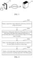
- a planar contour recognition method provided in this application may be applied to an application environment shown in FIG. 1 .
- the application environment includes a terminal 102 and a server 104.
- the terminal 102 performs collection on a target environment to obtain a target frame image, and displays the collected target frame image; the terminal 102 fits edge points of each object plane in the target frame image and edge points of a corresponding object plane in a previous frame image to obtain a fitting graph, and superimposes the fitting graph on the object plane for display; in the fitting graph, edge points that do not appear on the object plane of the previous frame image are deleted, the previous frame image being a frame image obtained before the target frame image by performing collection on the target environment; and a planar contour constructed by remaining edge points in the fitting graph is displayed on the object plane of the target frame image.
- a fitting progress of the fitting graph may include: sending, by the terminal 102, the target frame image and the previous frame image to the server 104; and fitting, by the server 104, the edge points of each object plane in the target frame image to obtain the fitting graph, and sending the fitting graph to the terminal 102, so that the fitting graph is superimposed on the object plane for display.
- the terminal 102 may be a smartphone, a tablet computer, a notebook computer, a desktop computer, a smart speaker, a smartwatch, or the like, but this application is not limited thereto.
- the server 104 may be an independent physical server, or may be a server cluster constituted by a plurality of physical servers, or may be a cloud server providing basic cloud computing services, such as a cloud server, a cloud database, cloud storage and a CDN.
- the terminal 102 and the server 104 may be connected in a communication connection mode such as Bluetooth, a universal serial bus (USB), or a network, which is not limited in this application.
- a communication connection mode such as Bluetooth, a universal serial bus (USB), or a network, which is not limited in this application.
- a planar contour recognition method is provided, which may be performed by the terminal 102, or may be performed by the terminal 102 and the server 104 in cooperation. Descriptions are made by using an example in which the method is performed by the terminal 102 in FIG. 1 , and the method includes the following steps: S202. Display a target frame image obtained by performing collection on a target environment.
- the target environment may be a working environment of the terminal.
- the target environment is, for example, an environment in which a robot sorts items in the express delivery field, or a road environment in which the robot walks during working.
- the target frame image may refer to an image obtained by the terminal by collecting an image or a video in the target environment through a built-in camera, or an image obtained by collecting an image or a video in the target environment through an independent camera.
- the target frame image may be a three-dimensional image carrying depth information, such as a depth image.
- the target frame image may be an image of a staircase in the target environment.
- the video is decoded to obtain target frame images, and then the target frame images obtained by decoding are displayed.
- the video is sent to the terminal in real time and decoded by the terminal to obtain target frame images, and then the target frame images obtained by decoding are displayed.
- the target frame images are video frames in the video.
- the shot target frame image is displayed on a display screen.
- the independent camera shoots the target environment at the preset time interval to obtain a target frame image
- the shot target frame image is sent to the terminal, and the terminal displays the received target frame image.
- the object plane may refer to a surface of an object displayed in the target frame image, that is, a surface of an unblocked object.
- the object plane may appear in the target frame image, or appear in the previous frame image.
- the object plane may be a horizontal plane or a curved plane. In subsequent embodiments, descriptions are made by using an example in which the object plane is a horizontal object plane.
- the object may refer to a target object that is in the target environment and shot in the target frame image. Surfaces of the object in various directions may be horizontal planes. In addition, the object may be in a specific geometric shape. For example, the object may be an express box for containing an express item, or a staircase, or the like.
- the fitting graph may refer to a closed curve diagram obtained by fitting edge points by using a curve line, or a closed graph obtained by fitting the edge points by using a straight line.
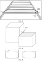
- a dashed graph is a fitting graph obtained by fitting edge points of a plane of a step of the staircase.
- corresponding edge points may alternatively be voxels of the object plane in the target frame image, or three-dimensional edge points of the target object in the target environment (that is, a real scenario).
- corresponding edge points may alternatively be two-dimensional pixels, or two-dimensional edge points of the target object in the target environment.
- a fitting degree of the edge points of the object plane may be determined based on the fitting graph displayed by superimposing.
- the fitting graph may be directly used as the planar contour of the object plane.
- S206 may be performed.
- the preset fitting condition may refer to whether a shape of the fitting graph of the object plane is a target shape. For example, for a rectangular object, whether the fitting graph is in a rectangular shape; or under a side-view angle, whether the fitting graph is in a rhombus shape.
- the fitting graph is obtained by performing edge point fitting operations to fit the edge points of each object plane in the target frame image and the edge points of the corresponding object plane in the previous frame image.
- the edge point fitting steps include: determining, by the terminal, a spatial position corresponding to each point in the target frame image according to the depth information; determining a plane on which each point is located based on the spatial position and a plane equation to obtain the object plane; and fitting the edge points of the object plane and the edge points of the object plane corresponding to the previous frame image to obtain the fitting graph.
- the terminal superimposes the obtained fitting graph on the object plane of the target frame image for display.
- the spatial position may be a spatial coordinate in a three-dimensional spatial coordinate system.
- the target frame image includes a graphic code carrying direction information.
- the steps of determining the spatial position corresponding to each point in the target frame image according to the depth information may specifically include: determining, by the terminal, a coordinate system reference direction according to the direction information carried by the graphic code; constructing a spatial coordinate system based on the coordinate system reference direction; and determining, in the spatial coordinate system, the spatial position corresponding to each point in the target frame image based on the depth information.
- the graphic code may be a barcode or a two-dimensional code, such as an Apriltag for indicating a direction.
- the terminal may calculate, according to the depth information, a distance between each point of an object in the target frame image and the camera, and distances between points of the object. According to the distances, the spatial position of each point of the object in the target frame image in the spatial coordinate system may be determined.
- the steps of determining the plane on which each point on the surface of the object is located may specifically include: inputting, by the terminal, the spatial position (that is, the spatial coordinate) and the plane equation to a planar fitting model; and fitting, by using the planar fitting model, the spatial position of each point of the object according to the plane equation, to obtain the plane on which each point is located, thereby obtaining the object plane of the plane.
- the terminal fits the edge points of the object plane by using a straight line or a curve line to obtain a closed curve diagram, or a closed graph formed by straight line segments.
- the closed curve diagram or the closed graph is determined as the fitting graph of the edge points of the object plane.
- the steps of fitting the edge points of the object plane and the edge points of the object plane corresponding to the previous frame image to obtain the fitting graph may specifically include: determining, by the terminal, a previous target frame image that includes the object plane in each of the previous frame images in a case that the object plane is a partial region plane of the object or blocked by another object in the target frame image; extracting edge points from an object plane of the previous target frame image; selecting target edge points from the edge points that are extracted from the object plane in the previous target frame image and the edge points of the object plane in the target frame image; and fitting the selected target edge points to obtain the fitting graph. Then, the terminal superimposes the obtained fitting graph on the object plane of the target frame image for display.
- the edge points are three-dimensional edge points.
- the previous frame image is a frame image obtained before the target frame image by performing collection on the target environment, for example, the previous frame image is a previous frame of image of the target frame image, or previous n frames (that is, a previous frame of image to a previous nth frame of image) of images collected before the target frame image.
- the previous target frame image refers to an image of the object plane including the object in the previous frame image.
- a process of selecting the target edge points may include: first, superimposing the previous target frame image on the target frame image, so that the edge points of the object plane in the target frame image and the edge points of the corresponding object plane in the previous target frame image are superimposed to obtain an edge point set; and then, selecting edge points from an edge point dense area of the edge point set. Selecting the edge points from the edge point dense area can avoid interference of discrete points. For example, after the edge points are superimposed, there may be some edge points that deviate from a normal range, and exclusion of these edge points can improve a fitting effect.
- a weight may be set for each frame image according to a distance between the camera and the target object, and then the target edge points are selected according to a magnitude of the weight. That is, more target edge points are selected from a frame image with a larger weight, and less target edge points are selected from a frame image with a smaller weight.
- steps of determining whether the object plane is the partial region plane of the object or whether the object plane is blocked by another object in the target frame image may specifically include: mapping, by the terminal, three-dimensional edge points into two-dimensional edge points; determining a convex polygon corresponding to the two-dimensional edge points, and calculating an area of the convex polygon; determining a bounding graph of the two-dimensional edge points, and calculating an area of the bounding graph; and determining that the object plane is the partial region plane of the object or blocked by another object in the target frame image in a case that a ratio of the area of the convex polygon to the area of the bounding graph reaches a preset ratio.
- the convex polygon means that if any one of edges of a polygon is extended infinitely in two directions to become a straight line, all other edges are beside the straight line.
- all interior angles of the polygon shall not be reflex angles, and a line segment between any two vertexes is located inside the polygon or on an edge of the polygon.
- steps of selecting the target edge points from the edge points that are extracted from the object plane in the previous target frame image and the edge points of the object plane in the target frame image may specifically include: determining, by the terminal, a first weight corresponding to the target frame image and a second weight corresponding to the previous target frame image, the first weight being unequal to the second weight; selecting, according to the first weight, a first target edge point from the edge points of the object planes in the target frame image, and selecting, according to the second weight, a second target edge point from the edge points that are extracted from the object plane in the previous target frame image; and using the first target edge point and the second target edge point as the target edge points.
- Magnitudes of the first weight and the second weight are related to a distance between the camera and an object in a case that the camera shoots an image. That is, in a case that the camera shoots an object in the target environment, the longer the distance is, the smaller a corresponding weight is. Similarly, in a case that the camera shoots the object in the target environment, the closer the distance is, the larger the corresponding weight is.
- the terminal determines a size of the fitting graph. In a case that the size is less than a preset size, the target frame image obtained by performing collection on the target environment is re-obtained, and S204 is performed. In a case that the size is greater than or equal to the preset size, S206 is performed.
- a size of the object plane may be selected to be checked, and the fitting is determined to be successful only when a threshold is met.
- the previous frame image is a frame image obtained before the target frame image by performing collection on the target environment, for example, the previous frame image is a previous frame of image of the target frame image, or previous n frames of images collected before the target frame image, or a nth frame of image collected before the target frame image.
- S206 may specifically include: if an edge point in the fitting graph does not appear on the object plane in the previous frame image, or the edge point in the fitting graph does not appear in the planar contour corresponding to the object plane in the previous frame image, deleting the edge points that do not appear from the fitting graph.
- two objects in the figure are cubic objects.
- a fitting graph (for example, a gray region in the figure) of an upper surface of one of the two objects extends out along a side surface of the other object.
- a cause to this phenomenon is that there is a relatively large error in the depth information in this case, and therefore, planar fitting goes wrong. Therefore, for a fitting graph obtained by fitting edge points of object planes in a plurality of frames of images, edge points that do not appear on the object plane in the previous frame image are deleted from the fitting graph (that is, edge points in the dashed oval box in the figure are deleted), the edge points that do not appear on the object plane in the previous frame image being outliers. In this way, it can be avoided that a fitting error occurs in the fitting progress, thereby improving correctness of the fitting graph.
- the planar contour may refer to a contour of a surface of an object, and the contour may be a rectangular contour, or a contour of another shape.
- the terminal may generate a planar graph bounding the remaining edge points in the fitting graph.
- the planar graph is the planar contour of the object.
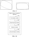
- a dashed line part on a left side of the figure is an original fitting graph
- a dashed line part on a right side of the figure is a new fitting graph obtained after the edge points that do not appear on the object plane in the previous frame image are deleted from the fitting graph, so as to construct the planar contour of the object according to the new fitting graph, thereby improving recognition accuracy of the planar contour of the object.
- the terminal can perform a corresponding operation.
- the terminal can perform different operations for different application scenarios. The operations performed by the terminal are described in the following scenarios:
- Scenario 1 an application scenario in which a robot moves.
- the robot determines a robot moving path in each planar contour constructed by using the target frame image, or selects a robot landing point in the planar contour; and then the robot moves according to the robot moving path or the robot landing point.
- a robot in a movement process, there is a need to plan a moving path on a road ahead (which may include the staircase in FIG. 3 ).
- a quadruped robot in a movement process, there is a need to select a landing point on a road, to avoid missing a step or colliding with another object.
- Scenario 2 an application scenario in which a robot clamps a target object.
- the foregoing object plane is region of a plane corresponding to the target object clamped by a robotic arm.
- the robotic arm determines a size, an orientation, and a spatial position of the target object according to the planar contour, clamps the target object based on the size, orientation, and spatial position of the target object, and places the clamped target object at a designated position.
- the size may refer to at least two of a length, a width, and a height of the target object.
- the orientation may refer to a direction towards which the target object faces, or may refer to a direction in which the target object is placed, for example, an express box is placed in a forward direction of the robotic arm.
- the steps of placing the clamped target object at the designated position may specifically include: collecting, by the terminal, an environment image at the designated position in a process of moving the robotic arm to place the target object; fitting edge points of each target object plane in the environment image and edge points of a corresponding target object plane in a previous frame environment image to obtain a target fitting graph; deleting, in the target fitting graph, the edge points that do not appear on the target object plane of the previous frame environment image, the previous frame environment image being a frame image collected before the environment image; constructing a target planar contour by using remaining edge points in the target fitting graph; determining a placement posture of the target object according to the target planar contour; and placing the target object on the target object plane according to the placement posture.
- the placement posture is a position at which the target object is placed and an orientation of the target object.
- a target planar contour corresponding to the another object can be recognized by using the foregoing method, and then a size and a spatial position of the another object are determined according to the target planar contour, and subsequently, the target object is placed on the another object according to the size and the spatial position of the another object, to ensure that the target object is free from collision during placing and is placed right above the target object.
- Scenario 3 an application scenario of augmented reality.
- the terminal is an AR device
- a size and a spatial position of the planar contour are determined, and a virtual identifier about the size and the spatial position is generated.
- the AR device displays a real picture about the target environment, the virtual identifier is displayed near the object in the real picture.
- the target frame image is obtained by performing collection on the target environment, and by fitting the edge points of each object plane in the target frame image and the edge points of the corresponding object plane in the previous frame image, the fitting graph of each object plane is obtained. If the edge points in the fitting graph do not appear in the object plane of the previous frame image, the edge points that do not appear are deleted as the outliers, to obtain the planar contour constructed by the remaining edge points, so that the planar contour of each object in the target frame image can be recognized without using deep learning, thereby reducing training time, and effectively improving efficiency of recognizing the planar contour of the target object.
- edge points that do not appear are deleted as the outliers to obtain the planar contour of the object, so that a plurality of objects can be placed in a staggered manner, thereby affecting recognition of the planar contour, and improving the recognition accuracy of the planar contour.
- a planar contour recognition method is provided, which may be performed by the terminal 102, or may be performed by the server 104, or may be performed by the terminal 102 and the server 104 in cooperation. Descriptions are made by using an example in which the method is performed by the terminal 102 in FIG. 1 , and the method includes the following steps:
- the target environment may be a working environment of the terminal.
- the terminal is, for example, an environment in which a robot sorts items in the express delivery field, or a road environment in which the robot walks during working.
- the target frame image may refer to an image obtained by the terminal by collecting an image or a video in the target environment through a built-in camera, or an image obtained by collecting an image or a video in the target environment through an independent camera.
- the target frame image may be a three-dimensional image carrying depth information, such as a depth image.
- the target frame image may be an image of a staircase in the target environment.
- the video is decoded to obtain a target frame image.
- the video is sent to the terminal in real time and decoded by the terminal to obtain a target frame image.
- the target frame image is a video frame in the video.
- the terminal uses the built-in camera to shoot the target environment at a preset time interval to obtain a target frame image, or uses the independent camera to shoot the target environment at the preset time interval to obtain a target frame image, and then the shot target frame image is transmitted to the terminal.
- the terminal may display the target frame image through a display screen after obtaining the target frame image.
- the previous frame image is a frame image obtained before the target frame image by performing collection on the target environment.
- the object plane may refer to a surface of an object displayed in the target frame image, that is, a surface of an unblocked object.
- the object plane may be a horizontal plane or a curved plane. In subsequent embodiments, descriptions are made by using an example in which the object plane is a horizontal object plane.
- the object may refer to a target object that is in the target environment and shot in the target frame image. Surfaces of the object in various directions may be horizontal planes. In addition, the object may be in a specific geometric shape. For example, the object may be an express box for containing an express item, or a staircase, or the like.
- the fitting graph may refer to a closed curve diagram obtained by fitting edge points by using a curve line, or a closed graph obtained by fitting edge points by using a straight line.
- a dashed graph is a fitting graph obtained by fitting edge points of a plane of a step of the staircase. Since the target frame image is a three-dimensional image, corresponding edge points may be three-dimensional edge points.
- the corresponding edge points may alternatively be voxels of the object plane in the target frame image, or three-dimensional edge points of the target object in the target environment (that is, a real scenario).
- corresponding edge points may alternatively be two-dimensional pixels, or two-dimensional edge points of the target object in the target environment.
- the terminal determines a spatial position corresponding to each point in the target frame image according to the depth information; determines a plane on which each point is located according to the spatial position and a plane equation to obtain the object plane; and fits the edge points of the object plane and the edge points of the object plane corresponding to the previous frame image to obtain the fitting graph.
- the spatial position may be a spatial coordinate in a three-dimensional spatial coordinate system.
- the target frame image includes a graphic code carrying direction information.
- the steps of determining the spatial position corresponding to each point in the target frame image according to the depth information may specifically include: determining, by the terminal, a coordinate system reference direction according to the direction information carried by the graphic code; constructing a spatial coordinate system based on the coordinate system reference direction; and determining, in the spatial coordinate system, the spatial position corresponding to each point in the target frame image based on the depth information.
- the graphic code may be a barcode or a two-dimensional code, such as an Apriltag for indicating a direction.
- a coordinate reference direction (which may also be referred to as a positive direction) of the spatial coordinate system may be determined by using the Apriltag, and the coordinate reference direction is used as an x-axis direction. Then, a normal direction of the object plane corresponding to the object is used as a z-axis direction, and a cross product direction of the x-axis direction and the z-axis direction is used as a y-axis direction.
- the x-axis direction is denoted as a vector a
- the z-axis direction is denoted as a vector b
- a cross product direction of the vector and the vector b is denoted as a direction of axb
- the direction of a ⁇ b is that: four fingers point to a starting from b, and a direction pointed by a thumb is a direction of b ⁇ a.
- the direction is perpendicular to a plane on which b and a are located.
- the terminal may calculate, according to the depth information, a distance between each point of an object in the target frame image and the camera, and distances between points of the object. According to the distances, the spatial position of each point of the object in the target frame image in the spatial coordinate system may be determined.
- the steps of determining a plane on which each point on the surface of the object is located may specifically include: inputting, by the terminal, the spatial position (that is, the spatial coordinate) and the plane equation to a planar fitting model; and fitting, by using the planar fitting model, the spatial position of each point of the object according to the plane equation, to obtain the plane on which each point is located, thereby obtaining the object plane of the plane.
- the terminal fits the edge points of the object plane by using the straight line or the curve line to obtain the closed curve diagram or the closed graph formed by straight line segments.
- the closed curve diagram or the closed graph is determined as the fitting graph of the edge points of the object plane.
- the steps of fitting the edge points of the object plane and the edge points of the object plane corresponding to the previous frame image to obtain the fitting graph may specifically include: determining, by the terminal, a previous target frame image that includes the object plane in each of the previous frame images in a case that the object plane is a partial region plane of the object or blocked by another object in the target frame image; extracting edge points from an object plane of the previous target frame image; selecting target edge points from the edge points that are extracted from the object plane in the previous target frame image and the edge points of the object plane in the target frame image; and fitting the selected target edge points to obtain the fitting graph.
- the edge points are three-dimensional edge points.
- the previous frame image is a frame image obtained before the target frame image by performing collection on the target environment, for example, the previous frame image is a previous frame of image of the target frame image, or previous n frames (that is, a previous frame of image to a previous nth frame of image) of images collected before the target frame image.
- the previous target frame image refers to an image of the object plane including the object in the previous frame image.
- a process of selecting the target edge points may include: first, superimposing the previous target frame image on the target frame image, so that the edge points of the object plane in the target frame image and the edge points of the corresponding object plane in the previous target frame image are superimposed to obtain an edge point set; and then, selecting edge points from an edge point dense area of the edge point set. Selecting the edge points from the edge point dense area can avoid interference of discrete points. For example, after the edge points are superimposed, there may be some edge points that deviate from a normal range, and exclusion of these edge points can improve a fitting effect.
- a weight may be set for each frame image according to a distance between the camera and the target object, and then the target edge points are selected according to a magnitude of the weight. That is, more target edge points are selected from a frame image with a larger weight, and less target edge points are selected from a frame image with a smaller weight.
- steps of determining whether the object plane is the partial region plane of the object or whether the object plane is blocked by another object in the target frame image may specifically include: mapping, by the terminal, three-dimensional edge points into two-dimensional edge points; determining a convex polygon corresponding to the two-dimensional edge points, and calculating an area of the convex polygon; determining a bounding graph of the two-dimensional edge points, and calculating an area of the bounding graph; and determining that the object plane is the partial region plane of the object or blocked by another object in the target frame image in a case that a ratio of the area of the convex polygon to the area of the bounding graph reaches a preset ratio.
- the convex polygon means that if any one of edges of a polygon is extended infinitely in two directions to become a straight line, all other edges are beside the straight line.
- all interior angles of the polygon shall not be reflex angles, and a line segment between any two vertexes is located inside the polygon or on an edge of the polygon.
- steps of selecting the target edge points from the edge points that are extracted from the object plane in the previous target frame image and the edge points of the object plane in the target frame image may specifically include: determining, by the terminal, a first weight corresponding to the target frame image and a second weight corresponding to the previous target frame image, the first weight being unequal to the second weight; selecting, according to the first weight, a first target edge point from the edge points of the object planes in the target frame image, and selecting, according to the second weight, a second target edge point from the edge points that are extracted from the object plane in the previous target frame image; and using the first target edge point and the second target edge point as the target edge points.
- Magnitudes of the first weight and the second weight are related to a distance between the camera and an object in a case that the camera shoots an image. That is, in a case that the camera shoots an object in the target environment, the longer the distance is, the smaller a corresponding weight is. Similarly, in a case that the camera shoots the object in the target environment, the closer the distance is, the larger the corresponding weight is.
- the terminal determines a size of the fitting graph. In a case that the size is less than a preset size, the target frame image obtained by performing collection on the target environment is re-obtained, and S604 is performed. In a case that the size is greater than or equal to the preset size, S606 is performed.
- a size of the object plane may be selected to be checked, and the fitting is determined to be successful only in a case that a threshold is met.
- the previous frame image is a frame image obtained before the target frame image by performing collection on the target environment, for example, the previous frame image is a previous frame of image of the target frame image, or previous n frames of images collected before the target frame image, or a nth frame of image collected before the target frame image.
- S606 may specifically include: if an edge point in the fitting graph does not appear on the object plane in the previous frame image, or the edge point in the fitting graph does not appear in the planar contour corresponding to the object plane in the previous frame image, deleting the edge point that does not appear from the fitting graph.
- two objects in the figure are cubic objects.
- a fitting graph (for example, a gray region in the figure) of an upper surface of one of the two objects extends out along a side surface of the other object.
- a cause to this phenomenon is that there is a relatively large error in the depth information in this case, and therefore, planar fitting goes wrong. Therefore, for a fitting graph obtained by fitting edge points of object planes in a plurality of frames of images, edge points that do not appear on the object plane in the previous frame image are deleted from the fitting graph (that is, edge points in the dashed oval box in the figure are deleted), the edge points that do not appear on the object plane in the previous frame image being outliers. In this way, it can be avoided that a fitting error occurs in the fitting progress, thereby improving correctness of the fitting graph.
- the planar contour may refer to a contour of the object plane of the target object, and the contour may be a rectangular contour, or a contour of another shape.
- the terminal may generate a planar graph bounding the remaining edge points in the fitting graph.
- the planar graph is the planar contour of the object.
- a dashed line part on a left side of the figure is an original fitting graph
- a dashed line part on a right side of the figure is a new fitting graph obtained after the edge points that do not appear on the object plane in the previous frame image are deleted from the fitting graph, so as to construct the planar contour of the object according to the new fitting graph, thereby improving recognition accuracy of the planar contour of the object.
- the terminal can perform a corresponding operation.
- the terminal can perform different operations for different application scenarios. The operations performed by the terminal are described in the following scenarios:
- Scenario 1 an application scenario in which a robot moves.
- the robot determines a robot moving path in each planar contour constructed by using the target frame image, or selects a robot landing point in the planar contour; and then the robot moves according to the robot moving path or the robot landing point.
- a robot in a movement process, there is a need to plan a moving path on a road ahead (which may include the staircase in FIG. 3 ).
- a quadruped robot in a movement process, there is a need to select a landing point on a road, to avoid missing a step or colliding with another object.
- Scenario 2 an application scenario in which a robot clamps a target object.
- the foregoing object plane is a region of a plane corresponding to the target object.
- the robotic arm determines a size, an orientation, and a spatial position of the target object according to the planar contour, clamps the target object based on the size, orientation, and spatial position of the target object, and places the clamped target object at a designated position.
- the size may refer to at least two of a length, a width, and a height of the target object.
- the orientation may refer to a direction towards which the target object faces, or may refer to a direction in which the target object is placed, for example, an express box is placed in a forward direction of the robotic arm.
- the steps of placing the clamped target object at the designated position may specifically include: collecting, by the terminal, an environment image at the designated position in a process of moving the robotic arm to place the target object; fitting edge points of each target object plane in the environment image and edge points of a corresponding target object plane in a previous frame environment image to obtain a target fitting graph; deleting, in the target fitting graph, the edge points that do not appear on the target object plane of the previous frame environment image, the previous frame environment image being a frame image collected before the environment image; constructing a target planar contour by using remaining edge points in the target fitting graph; determining a placement posture of the target object according to the target planar contour; and placing the target object on the target object plane according to the placement posture.
- the placement posture is a position at which the target object is placed and an orientation of the target object.
- a target planar contour corresponding to the another object can be recognized by using the foregoing method, and then a size and a spatial position of the another object are determined according to the target planar contour, and subsequently, the target object is placed on the another object according to the size and the spatial position of the another object, to ensure that the target object is free from collision during placing and is placed right above the target object.
- Scenario 3 an application scenario of augmented reality.
- the terminal is an AR device
- a size and a spatial position of the planar contour are determined, and a virtual identifier about the size and the spatial position is generated.
- the AR device displays a real picture about the target environment, the virtual identifier is displayed near the object in the real picture.
- the target frame image is obtained by performing collection on the target environment, and by fitting the edge points of each object plane in the target frame image and the edge points of the corresponding object plane in the previous frame image, the fitting graph of each object plane is obtained. If the edge points in the fitting graph do not appear in the object plane of the previous frame image, the edge points that do not appear are deleted as the outliers, to obtain the planar contour constructed by the remaining edge points, thereby reducing the training time consumed by using the deep learning, and effectively improving the efficiency of recognizing the planar contour of the target object.
- edge points that do not appear are deleted as the outliers to obtain the planar contour of the object, so that a plurality of objects can be placed in a staggered manner, thereby affecting recognition of the planar contour, and improving the recognition accuracy of the planar contour.
- each video frame includes RGB color images or depth images (the depth image is the foregoing target frame image carrying the depth information) at different moments.
- a rectangular contour recognition method is mainly implemented based on the depth information.
- An example of rectangular contour recognition is shown in FIG. 3 , and a surface of each step in the figure is rectangular.
- a rectangular plane obtained by performing time-domain fusion on the step in the depth image is represented by dashed lines, and a final rectangular contour is represented by black solid lines.
- a vertex of the rectangular contour is represented by a cross-shaped pattern, as shown in FIG. 3 .
- the rectangular plane obtained by performing the time-domain fusion refers to a rectangular plane obtained by fusing three-dimensional edge points of the step plane in the depth images at different moments in the spatial coordinate system at a certain moment, and then extracting target three-dimensional edge points from fused three-dimensional edge points, and subsequently, fitting the target edge points, that is, the fitting graph in the foregoing embodiments.
- the rectangular plane in the target environment may be relatively large, and a visual field of a single frame image may not cover the entire rectangular plane.
- a fitted plane in the target environment is a target rectangular plane is recognized and screened in real time frame by frame; and on the other hand, in a process of recognizing the rectangular plane, three-dimensional edge points of the rectangular planes belonging to the same object in different frame images are fused, and a more accurate and complete rectangular region is optimized and extracted on this basis.
- Spatial positions of all rectangular planes in the target environment can be determined in a case that the rectangular contour in the target environment is recognized, so that corresponding operations can be performed.
- the operations are described according to the following different scenarios:
- Scenario 1 a sorting scenario for items
- the mechanical arm needs to clamp or move an object of a cubic type
- visual information such as a size, an orientation, and a spatial position in a three-dimensional space of such an object
- the mechanical arm can accurately clamp the target object based on the visual information.
- the mechanical arm may further place the object at a designated position in the target environment, and controls a posture of the target object after the target object is placed, to avoid collision between the target object and another object in the target environment.
- Scenario 2 a scenario in which a mobile robot moves
- the mobile robot may be a quadruped robot. If there is a highly difficult scenario in which a step exists in a movement process of the quadruped robot, the method may provide a precise landing region for the quadruped robot in real time, to prevent the quadruped robot from missing a step, or prevent a foot of the quadruped robot from colliding with another object in the target environment in the movement process.
- the quadruped robot it is convenient for the quadruped robot to choose a more reasonable landing point, or to plan a more reasonable moving path.
- Real-time performance Whether the fitted rectangular plane is a real rectangular plane of the target object can be recognized and screened in real time frame by frame on a computer platform, and the rectangular contour is also recognized in real time.
- the rectangular contour recognition in this embodiment is universal, and may be applicable to most scenarios.
- a rectangular contour recognition algorithm in this embodiment is robust, with few failures.
- a rectangular contour recognition process needs to face some core problems, which are specifically as follows: 1) The rectangular plane is not a centrosymmetric graph, and a positive direction of the rectangular plane needs to be obtained. 2) With limited computing resources, processing of three-dimensional (3D) data usually requires a series of complex operations, which is a challenge to real-time performance. 3) After planar fitting is completed for the entire scenario, various types of fitted planes are extracted, and the target rectangular plane needs to be screened out. 4) If a plane of a rectangular object in a scenario is relatively large, single rectangular contour recognition may merely obtain a part of a rectangular plane, and a more complete rectangular region needs to be obtained as much as possible.
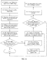
- this embodiment provides a proper solution, and a flowchart thereof is shown in FIG. 8 .
- the graphic code may be an Apriltag, or another graph used for indicating a direction.
- An example in which the graphic code is the Apriltag is used.
- a spatial coordinate system is constructed in the rectangular plane of the target object. As shown in FIG. 7 , a normal line of the plane is used as a z-axis of the coordinate system, and the positive direction of the plane is used as an x-axis of the coordinate system.
- the positive direction of the plane is a direction parallel to any pair of sides of the rectangle.
- the positive direction is provided by using the Apriltag, that is, an Apriltag is placed before the target object, so that an orientation thereof is parallel to a pair of sides of the rectangular plane of the target object, which can help improve the universality and robustness for scenarios.
- a planar fitting algorithm By using a planar fitting algorithm, a plurality of planes in the depth image are extracted as an input, and specific information is coordinates of all three-dimension points corresponding to each plane in a world coordinate system and a plane equation of the plane.
- a single rectangular plane fitted in S2 includes a relatively large quantity of three-dimensional edge points
- three-dimensional edge points corresponding to each rectangular plane are extracted through a current step. Subsequent operations are mainly performed based on these three-dimensional edge points, otherwise the entire algorithm is difficult to be real-time.
- the three-dimensional edge points are mapped into the two-dimensional edge points, and a related operation is performed. Specific operations are as follows: First, the three-dimensional edge points of the object plane are mapped onto the object plane fitted in S2, and then a two-dimensional coordinate system is constructed on the object plane, to obtain two-dimensional coordinates corresponding to the three-dimensional edge points, that is, the two-dimensional edge points are obtained.
- the convex polygon corresponding to the two-dimensional edge points of the object plane is used to represent the rectangular region of the target object, and then the area s1 corresponding to the convex polygon in a two-dimensional coordinate system is calculated. Since the edge points obtained in S3 and S4 are discrete, and the error of the depth information may cause the two-dimensional edge points to present irregular shapes (for example, jagged shapes), by using the convex polygon to represent the rectangular region of the target object, interference from the foregoing uncontrollable factors can be avoided.
- irregular shapes for example, jagged shapes
- a left figure represents a fitting result obtained by using a conventional method. If the positive direction of the object plane is unknown, the fitted bounding rectangle usually differs greatly from the real rectangular contour.
- a right figure shows fitting of the minimum bounding rectangle that meets expectation.
- S7 Determine whether a ratio of s1 to s2 is greater than a preset threshold.
- the preset threshold may be set according to an actual situation.
- An example in which the preset threshold is equal to 0.9 is used for description herein. If the fitted object plane in S2 differs greatly from the rectangle, an overlapping area between a convex polygon of a certain plane corresponding to S5 and S6 and a minimum bounding rectangle is limited. Based on such a feature, the preset threshold is selected to be 0.9 for screening a non-rectangular plane.
- a blocking situation is usually improved gradually in a process in which the object plane approach the camera from far to near; and on the other hand, in the time domain process, fusion of the rectangular planar contours may also relieve an impact from blocking to a certain extent.
- the foregoing preset threshold may be adjusted correspondingly.
- the time-domain fusion is performed on three-dimensional edge points of object planes of each frame.
- a fused object is a plurality sets of three-dimensional edge points corresponding to the same rectangular plane in the time domain process.
- three-dimensional edge points at different moments are converted to be under a coordinate system at a certain moment, and then, three-dimensional edge points of these discrete points are re-extracted.
- An objective of extracting the three-dimensional edge points is to reduce an amount of data.
- the rectangular planes of the target object are continuously fused in the time domain process, to obtain a result that is approximate to a needed rectangular region.
- d a distance between a center point or a mean point of a 3D rectangular plane and the optical center of the camera
- w i a weight of a to-be-optimized parameter corresponding to an ith frame
- c i a to-be-optimized parameter (for example, a normal) of the rectangular plane equation detected by the ith frame.
- w i 1 d 2
- c w i c i ⁇ w i
- the regular rectangular contour is obtained, that is, four vertexes of the rectangular contour are obtained.
- the positive direction and the normal are respective provided in S1 and S2, and the spatial coordinate system of the rectangular plane is constructed based on the positive direction and the normal.
- the normal is the z-axis
- the positive direction is the x-axis
- y is obtained by a cross product of the x-axis and z-axis.
- an x-y plane coincides with the rectangular plane.
- x min , x max , y min , y max three-dimensional points corresponding to the rectangular plane are projected onto the x-y plane, to obtain x min , x max , y min , y max .
- coordinates of the four vertexes of the rectangular contour are ( x min , y min ), ( x min , y max ), ( x max , y min ), and ( x max , y max ).
- a z value corresponding to each vertex may be obtained by using the plane equation.
- a size of the rectangular plane may be selected to be checked, and only in a case that the threshold is met, it is considered that the recognition is successful, thereby obtaining the rectangular contour corresponding to the rectangular plane.
- This step is specific to a complex but common scenario, for example, a case in which the camera is far away from a certain rectangular plane, an incident angle between the optical center of the camera and the rectangular plane is relatively large, and a plurality of objects are placed in a staggered manner in the scenario.
- two cubes are used as an example.
- the gray region is a planar fitting region, and it can be seen that a fitting object plane of the upper surface of the front cubic object extends out along the side surface of the rear cubic object, resulting in a planar fitting error.
- a left figure represents a rectangular planar contour recognition result showing that there are outliers in the discrete points obtained by the time-domain fusion in step 8
- a right figure represents a result after the optimization of the rectangular planar contour recognition.
- the final rectangular contour becomes more complete and accurate.
- steps in the flowcharts of FIG. 2 , FIG. 6 , and FIG. 8 are sequentially displayed according to indication of arrows, the steps are not necessarily sequentially performed in the sequence indicated by the arrows. Unless clearly specified in this specification, there is no strict sequence limitation on the execution of the steps, and the steps may be performed in another sequence. Moreover, at least some of the steps in FIG. 2 , FIG. 6 , and FIG. 8 may include a plurality of steps or a plurality of stages. These steps or stages are not necessarily performed at the same moment, but may be performed at different moments. These steps or stages are not necessarily executed sequentially, but may be performed in turn or alternately with another step or at least some of steps or stages of the another step.
- a planar contour recognition apparatus is provided.
- the apparatus may become a part of a computer device by using a software module, or a hardware module, or a combination thereof.
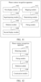
- the apparatus specifically includes: a first display module 1002, a superimposing module 1004, a deletion module 1006, and a second display module 1008.
- the first display module 1002 is configured to display a target frame image obtained by performing collection on a target environment
- the superimposing module 1004 is configured to superimpose a fitting graph obtained by fitting edge points of each object plane in the target frame image and edge points of a corresponding object plane in a previous frame image on the object plane for display, the previous frame image being a frame image obtained before the target frame image by performing collection on the target environment.
- the deletion module 1006 is configured to delete, in the fitting graph, the edge points that do not appear on the object plane of the previous frame image.
- the second display module 1008 is configured to display, on the object plane of the target frame image, a planar contour constructed by remaining edge points in the fitting graph.
- the target frame image includes depth information, and as shown in FIG. 11 , the apparatus further includes a fitting module 1010.
- the fitting module 1010 is configured to: determine a spatial position corresponding to each point in the target frame image according to the depth information; determine a plane on which each point is located according to the spatial position and a plane equation to obtain the object plane; and fit the edge points of the object plane and the edge points of the object plane corresponding to the previous frame image to obtain the fitting graph.
- the fitting module 1010 is further configured to: determine a previous target frame image that includes the object plane in each of the previous frame images in a case that the object plane is a partial region plane of the object or blocked by another object in the target frame image; extract edge points from an object plane of the previous target frame image; select target edge points from the edge points that are extracted from the object plane in the previous target frame image and the edge points of the object plane in the target frame image; and fit the selected target edge points to obtain the fitting graph.
- the edge points are three-dimensional edge points, and as shown in FIG. 11 , the apparatus further includes a mapping module 1012 and a determining module 1014.
- the mapping module 1012 is configured to map the three-dimensional edge points into two-dimensional edge points.
- the determining module 1014 is configured to: determine a convex polygon corresponding to the two-dimensional edge points, and calculate an area of the convex polygon; determine a bounding graph of the two-dimensional edge points, and calculate an area of the bounding graph; and determine that the object plane is the partial region plane of the object or blocked by another object in the target frame image in a case that a ratio of the area of the convex polygon to the area of the bounding graph reaches a preset ratio.
- the target frame image is obtained by performing collection on the target environment, and by fitting the edge points of each object plane in the target frame image and the edge points of the corresponding object plane in the previous frame image, the fitting graph of each object plane is obtained. If the edge points in the fitting graph do not appear in the object plane of the previous frame image, the edge points that do not appear are deleted as the outliers, to obtain the planar contour constructed by the remaining edge points, so that the planar contour of each object in the target frame image can be recognized without using deep learning, thereby reducing training time, and effectively improving efficiency of recognizing the planar contour of the target object.
- edge points that do not appear are deleted as the outliers to obtain the planar contour of the object, so that a plurality of objects can be placed in a staggered manner, thereby affecting recognition of the planar contour, and improving the recognition accuracy of the planar contour.
- a planar contour recognition apparatus is provided.
- the apparatus may become a part of a computer device by using a software module, or a hardware module, or a combination thereof.
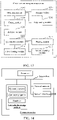
- the apparatus specifically includes: an obtaining module 1202, a fitting module 1204, a deletion module 1206, and a construction module 1208.
- the obtaining module 1202 is configured to obtain a target frame image obtained by performing collection on a target environment.
- the fitting module 1204 is configured to fit edge points of each object plane in the target frame image and edge points of a corresponding object plane in a previous frame image to obtain a fitting graph, the previous frame image being a frame image obtained before the target frame image by performing collection on the target environment.
- the deletion module 1206 is configured to delete, in the fitting graph, the edge points that do not appear on the object plane of the previous frame image.
- the construction module 1208 is configured to recognize a contour constructed by remaining edge points in the fitting graph as a planar contour.
- the apparatus further includes a first planning module 1210.
- the first planning module 1210 is configured to: determine a robot moving path in each planar contour constructed by using the target frame image, or select a robot landing point in the planar contour; and move according to the robot moving path or the robot landing point.
- the object plane is a region of a plane corresponding to a target object.
- the apparatus further includes a second planning module 1212.
- the second planning module 1212 is configured to: determine a size, an orientation, and a spatial position of the target object according to the planar contour; clamp the target object based on the size, orientation, and spatial position of the target object; and place the clamped target object at a designated position.
- the apparatus further includes a placing module 1214.
- the obtaining module 1202 is further configured to collect, in a process of moving a robotic arm to place the target object, an environment image at the designated position.
- the fitting module 1204 is further configured to fit edge points of each target object plane in the environment image and edge points of a corresponding target object plane in a previous frame environment image to obtain a target fitting graph.
- the deletion module 1206 is further configured to delete, in the target fitting graph, the edge points that do not appear on the target object plane of the previous frame environment image, the previous frame environment image being a frame image collected before the environment image.
- the construction module 1208 is further configured to construct a target planar contour by using remaining edge points in the target fitting graph.
- the placing module 1214 is configured to determine a placement posture of the target object according to the target planar contour, and place the target object on the target object plane according to the placement posture.
- the target frame image includes the depth information.
- the fitting module 1204 is further configured to: determine a spatial position corresponding to each point in the target frame image according to the depth information; determine a plane on which each point is located according to the spatial position and a plane equation to obtain the object plane; and fit the edge points of the object plane and the edge points of the object plane corresponding to the previous frame image to obtain the fitting graph.
- the target frame image includes a graphic code carrying direction information.
- the fitting module 1204 is further configured to: determine a coordinate system reference direction according to the direction information carried by the graphic code; construct a spatial coordinate system based on the coordinate system reference direction; and determine, in the spatial coordinate system, the spatial position corresponding to each point in the target frame image based on the depth information.
- the fitting module 1204 is further configured to: determine a previous target frame image that includes the object plane in each of the previous frame images in a case that the object plane is a partial region plane of the object or blocked by another object in the target frame image; extract edge points from an object plane of the previous target frame image; select target edge points from the edge points that are extracted from the object plane in the previous target frame image and the edge points of the object plane in the target frame image; and fit the selected target edge points to obtain the fitting graph.
- the edge points are three-dimensional edge points, and as shown in FIG. 13 , the apparatus further includes a mapping module 1216 and a determining module 1218.
- the mapping module 1216 is configured to map the three-dimensional edge points into two-dimensional edge points.
- the determining module 1218 is configured to: determine a convex polygon corresponding to the two-dimensional edge points, and calculate an area of the convex polygon; determine a bounding graph of the two-dimensional edge points, and calculate an area of the bounding graph; and determine that the object plane is the partial region plane of the object or blocked by another object in the target frame image in a case that a ratio of the area of the convex polygon to the area of the bounding graph reaches a preset ratio.
- the fitting module 1204 is further configured to: determine a first weight corresponding to the target frame image and a second weight corresponding to the previous target frame image, the first weight being unequal to the second weight; select, according to the first weight, a first target edge point from the edge points of the object planes in the target frame image, and select, according to the second weight, a second target edge point from the edge points that are extracted from the object plane in the previous target frame image; and use the first target edge point and the second target edge point as the target edge points.
- the determining module 1218 is further configured to determine a size of the fitting graph.
- the obtaining module 1202 is further configured to re-obtain the target frame image obtained by performing collection on the target environment in a case that the size is less than a preset size.
- the deletion module 1206 is further configured to perform the step of deleting, in the fitting graph, the edge points that do not appear on the object plane of the object in the previous frame image in a case that the size is greater than or equal to the preset size.
- the target frame image is obtained by performing collection on the target environment, and by fitting the edge points of each object plane in the target frame image and the edge points of the corresponding object plane in the previous frame image, the fitting graph of each object plane is obtained. If the edge points in the fitting graph do not appear in the object plane of the previous frame image, the edge points that do not appear are deleted as the outliers, to obtain the planar contour constructed by the remaining edge points, thereby reducing the training time consumed by using the deep learning, and effectively improving the efficiency of recognizing the planar contour of the target object.
- edge points that do not appear are deleted as the outliers to obtain the planar contour of the object, so that a plurality of objects can be placed in a staggered manner, thereby affecting recognition of the planar contour, and improving the recognition accuracy of the planar contour.
- planar contour recognition apparatus For a specific limitation on the planar contour recognition apparatus, refer to the limitation on the planar contour recognition method above. Details are not described herein again.
- the modules in the foregoing planar contour recognition apparatus may be implemented entirely or partially by software, hardware, or a combination thereof.
- the foregoing modules may be built in or independent of a processor of a computer device in a hardware form, or may be stored in a memory of the computer device in a software form, so that the processor invokes and performs an operation corresponding to each of the foregoing modules.
- a computer device is provided.
- the computer device may be a server, and an internal structure diagram thereof may be shown in FIG. 14 .
- the computer device includes a processor, a memory, and a network interface that are connected by using a system bus.
- the processor of the computer device is configured to provide computing and control capabilities.
- the memory of the computer device includes a non-volatile storage medium and an internal memory.
- the non-volatile storage medium stores an operating system, a computer program, and a database.
- the internal memory provides an environment for running of the operating system and the computer program in the non-volatile storage medium.
- the database of the computer device is configured to store image data.
- the network interface of the computer device is configured to communicate with an external terminal through a network connection.
- the computer program is executed by the processor to implement a planar contour recognition method.
- a computer device is provided.
- the computer device may be a terminal, and an internal structure diagram thereof may be shown in FIG. 15 .
- the computer device includes a processor, a memory, a communication interface, a display screen, and an input apparatus that are connected by using a system bus.
- the processor of the computer device is configured to provide computing and control capabilities.
- the memory of the computer device includes a non-volatile storage medium and an internal memory.
- the non-volatile storage medium stores an operating system and a computer program.
- the internal memory provides an environment for running of the operating system and the computer program in the non-volatile storage medium.
- the communication interface of the computer device is configured to communicate with an external terminal in a wired or wireless manner.
- the wireless manner can be implemented through WIFI, an operator network, near field communication (NFC), or other technologies.
- the computer program is executed by the processor to implement a planar contour recognition method.
- the display screen of the computer device may be a liquid crystal display screen or an electronic ink display screen.
- the input apparatus of the computer device may be a touch layer covering the display screen, or may be a key, a trackball, or a touch pad disposed on a housing of the computer device, or may be an external keyboard, a touch pad, a mouse, or the like.
- FIG. 14 and FIG. 15 are only block diagrams of a partial structure related to the solution of this application, and do not limit the computer device to which the solution of this application is applied.
- the computer device may include more or fewer components than those shown in figures, or some components may be combined, or different component deployment may be used.
- a computer device including a memory and a processor, the memory storing a computer program, the computer program, when executed by the processor, causing the processor to perform the steps of the foregoing method embodiments.
- a computer readable storage medium storing a computer program, the computer program, when executed by a processor, performing the steps in the foregoing method embodiments.
- a computer program product or a computer program includes computer instructions, and the computer instructions are stored in a computer-readable storage medium.
- the processor of the computer device reads the computer instructions from the computer-readable storage medium, and the processor executes the computer instructions, to cause the computer device to perform the steps in the method embodiments.
- a person of ordinary skill in the art may understand that some or all procedures in the foregoing method embodiments may be implemented by a computer program instructing related hardware.
- the computer program may be stored in a non-volatile computer-readable storage medium, and in case that the computer program is executed, the procedures of the foregoing method embodiments may be performed.
- Any reference to a memory, a storage, a database, or another medium used in the embodiments provided in this application may include at least one of a non-volatile memory and a volatile memory.
- the non-volatile memory may include a read-only memory (ROM), a magnetic tape, a floppy disk, a flash memory, an optical memory, and the like.
- the volatile memory may include a random access memory (RAM) or an external cache.
- the RAM is available in a plurality of forms, such as a static RAM (SRAM) or a dynamic RAM (DRAM).
Landscapes
- Engineering & Computer Science (AREA)
- Computer Vision & Pattern Recognition (AREA)
- Physics & Mathematics (AREA)
- General Physics & Mathematics (AREA)
- Theoretical Computer Science (AREA)
- Software Systems (AREA)
- Multimedia (AREA)
- Image Analysis (AREA)
Applications Claiming Priority (2)
| Application Number | Priority Date | Filing Date | Title |
|---|---|---|---|
| CN202010901647.7A CN112102342B (zh) | 2020-09-01 | 2020-09-01 | 平面轮廓识别方法、装置、计算机设备和存储介质 |
| PCT/CN2021/114064 WO2022048468A1 (zh) | 2020-09-01 | 2021-08-23 | 平面轮廓识别方法、装置、计算机设备和存储介质 |
Publications (2)
| Publication Number | Publication Date |
|---|---|
| EP4131162A1 true EP4131162A1 (de) | 2023-02-08 |
| EP4131162A4 EP4131162A4 (de) | 2023-11-01 |
Family
ID=73756970
Family Applications (1)
| Application Number | Title | Priority Date | Filing Date |
|---|---|---|---|
| EP21863535.7A Pending EP4131162A4 (de) | 2020-09-01 | 2021-08-23 | Verfahren und vorrichtung zur erkennung planarer konturen, computervorrichtung und speichermedium |
Country Status (4)
| Country | Link |
|---|---|
| US (1) | US12412279B2 (de) |
| EP (1) | EP4131162A4 (de) |
| CN (1) | CN112102342B (de) |
| WO (1) | WO2022048468A1 (de) |
Families Citing this family (8)
| Publication number | Priority date | Publication date | Assignee | Title |
|---|---|---|---|---|
| CN112102342B (zh) | 2020-09-01 | 2023-12-01 | 腾讯科技(深圳)有限公司 | 平面轮廓识别方法、装置、计算机设备和存储介质 |
| CN113947675B (zh) * | 2021-09-18 | 2026-02-24 | 深圳智岩科技股份有限公司 | 显示装置的边缘提取方法、系统、装置、电子设备及介质 |
| CN116934658B (zh) * | 2022-04-02 | 2025-11-25 | 株洲中车时代电气股份有限公司 | 一种非接触式接触网参数检测方法及装置 |
| CN115435697B (zh) * | 2022-08-19 | 2025-12-23 | 上海大学 | 一种基于线性回归模型的微结构台阶高度表征方法 |
| CN115719492B (zh) * | 2022-11-29 | 2023-08-11 | 中国测绘科学研究院 | 一种面状要素宽窄特征识别方法、装置、设备及可读存储介质 |
| CN117095019B (zh) * | 2023-10-18 | 2024-05-10 | 腾讯科技(深圳)有限公司 | 一种图像分割方法及相关装置 |
| CN119197493B (zh) * | 2024-08-13 | 2025-04-15 | 深圳市人工智能与机器人研究院 | 一种面向人型机器人的实时阶梯环境分割与建图方法 |
| CN119228809B (zh) * | 2024-12-05 | 2025-03-18 | 安徽智质工程技术有限公司 | 一种基于视觉的槽式输送机状态检测方法 |
Family Cites Families (13)
| Publication number | Priority date | Publication date | Assignee | Title |
|---|---|---|---|---|
| CN101493889B (zh) * | 2008-01-23 | 2011-12-07 | 华为技术有限公司 | 对视频对象进行跟踪的方法及装置 |
| CN102006398A (zh) * | 2010-10-29 | 2011-04-06 | 西安电子科技大学 | 基于特征直线的船载摄像系统电子稳像方法 |
| US9393686B1 (en) * | 2013-03-15 | 2016-07-19 | Industrial Perception, Inc. | Moveable apparatuses having robotic manipulators and conveyors to facilitate object movement |
| US9996974B2 (en) * | 2013-08-30 | 2018-06-12 | Qualcomm Incorporated | Method and apparatus for representing a physical scene |
| US9607207B1 (en) * | 2014-03-31 | 2017-03-28 | Amazon Technologies, Inc. | Plane-fitting edge detection |
| KR101798041B1 (ko) * | 2016-06-29 | 2017-11-17 | 성균관대학교산학협력단 | 3차원 물체 인식 및 자세 추정 장치 및 그 방법 |
| CN109255801B (zh) * | 2018-08-03 | 2022-02-22 | 百度在线网络技术(北京)有限公司 | 视频中三维物体边缘追踪的方法、装置、设备及存储介质 |
| CN109241844B (zh) * | 2018-08-03 | 2020-11-17 | 百度在线网络技术(北京)有限公司 | 三维物体的姿态估计方法、装置、设备及存储介质 |
| CN111862179B (zh) | 2019-04-12 | 2022-02-18 | 北京城市网邻信息技术有限公司 | 三维对象建模方法与设备、图像处理装置及介质 |
| CN110189376B (zh) * | 2019-05-06 | 2022-02-25 | 达闼科技(北京)有限公司 | 物体定位方法及物体定位装置 |
| CN110081862B (zh) * | 2019-05-07 | 2021-12-24 | 达闼科技(北京)有限公司 | 一种对象的定位方法、定位装置、电子设备和可存储介质 |
| CN110992356B (zh) * | 2019-12-17 | 2024-03-08 | 深圳辰视智能科技有限公司 | 目标对象检测方法、装置和计算机设备 |
| CN112102342B (zh) * | 2020-09-01 | 2023-12-01 | 腾讯科技(深圳)有限公司 | 平面轮廓识别方法、装置、计算机设备和存储介质 |
-
2020
- 2020-09-01 CN CN202010901647.7A patent/CN112102342B/zh active Active
-
2021
- 2021-08-23 EP EP21863535.7A patent/EP4131162A4/de active Pending
- 2021-08-23 WO PCT/CN2021/114064 patent/WO2022048468A1/zh not_active Ceased
-
2022
- 2022-09-29 US US17/956,364 patent/US12412279B2/en active Active
Also Published As
| Publication number | Publication date |
|---|---|
| US20230015214A1 (en) | 2023-01-19 |
| CN112102342A (zh) | 2020-12-18 |
| US12412279B2 (en) | 2025-09-09 |
| EP4131162A4 (de) | 2023-11-01 |
| WO2022048468A1 (zh) | 2022-03-10 |
| CN112102342B (zh) | 2023-12-01 |
Similar Documents
| Publication | Publication Date | Title |
|---|---|---|
| US12412279B2 (en) | Planar contour recognition method and apparatus, computer device, and storage medium | |
| JP6031554B2 (ja) | 単眼カメラに基づく障害物検知方法及び装置 | |
| EP2430588B1 (de) | Objekterkennungsverfahren, objekterkennungsvorrichtung und autonomer mobiler roboter | |
| US10235764B2 (en) | Method, terminal, and storage medium for detecting collision between colliders in real-time virtual scene | |
| EP4102458B1 (de) | Verfahren und vorrichtung zur identifizierung einer szenenkontur, computerlesbares medium und elektronische vorrichtung | |
| US9639914B2 (en) | Portrait deformation method and apparatus | |
| JP5248806B2 (ja) | 情報処理装置、情報処理方法 | |
| JP4677536B1 (ja) | 3次元物体認識装置及び3次元物体認識方法 | |
| US8994726B1 (en) | Systems and methods for preparing a model of an environment for display | |
| CN110568447A (zh) | 视觉定位的方法、装置及计算机可读介质 | |
| CN109003325A (zh) | 一种三维重建的方法、介质、装置和计算设备 | |
| US20150138193A1 (en) | Method and device for panorama-based inter-viewpoint walkthrough, and machine readable medium | |
| JP2016192132A (ja) | 画像認識ar装置並びにその姿勢推定装置及び姿勢追跡装置 | |
| CN111460937B (zh) | 脸部特征点的定位方法、装置、终端设备及存储介质 | |
| CN108381549A (zh) | 一种双目视觉引导机器人快速抓取方法、装置及存储介质 | |
| CN110433467A (zh) | 基于双目视觉和蚁群算法的捡乒乓球机器人运行方法及设备 | |
| CN112766027A (zh) | 图像处理方法、装置、设备及存储介质 | |
| CN113379899A (zh) | 一种建筑工程工作面区域图像自动提取方法 | |
| CN111443808B (zh) | 一种生成目标的三维信息数据的方法及陀螺仪系统 | |
| CN115683109A (zh) | 基于cuda和三维栅格地图的视觉动态障碍物检测方法 | |
| CN114529801A (zh) | 一种目标检测的方法、装置、设备及存储介质 | |
| CN110827303B (zh) | 一种虚拟场景的图像编辑方法及装置 | |
| US10861174B2 (en) | Selective 3D registration | |
| CN118053105A (zh) | 一种基于双目视觉的动态环境定位与建图方法及相关装置 | |
| CN116934980A (zh) | 单体建筑模型的构建方法、设备及计算机可读存储介质 |
Legal Events
| Date | Code | Title | Description |
|---|---|---|---|
| STAA | Information on the status of an ep patent application or granted ep patent |
Free format text: STATUS: THE INTERNATIONAL PUBLICATION HAS BEEN MADE |
|
| PUAI | Public reference made under article 153(3) epc to a published international application that has entered the european phase |
Free format text: ORIGINAL CODE: 0009012 |
|
| STAA | Information on the status of an ep patent application or granted ep patent |
Free format text: STATUS: REQUEST FOR EXAMINATION WAS MADE |
|
| 17P | Request for examination filed |
Effective date: 20221102 |
|
| AK | Designated contracting states |
Kind code of ref document: A1 Designated state(s): AL AT BE BG CH CY CZ DE DK EE ES FI FR GB GR HR HU IE IS IT LI LT LU LV MC MK MT NL NO PL PT RO RS SE SI SK SM TR |
|
| A4 | Supplementary search report drawn up and despatched |
Effective date: 20231002 |
|
| RIC1 | Information provided on ipc code assigned before grant |
Ipc: G06T 7/181 20170101ALI20230926BHEP Ipc: G06T 7/162 20170101ALI20230926BHEP Ipc: G06T 7/13 20170101ALI20230926BHEP Ipc: G06T 7/70 20170101ALI20230926BHEP Ipc: G06T 7/12 20170101AFI20230926BHEP |
|
| DAV | Request for validation of the european patent (deleted) | ||
| DAX | Request for extension of the european patent (deleted) | ||
| STAA | Information on the status of an ep patent application or granted ep patent |
Free format text: STATUS: EXAMINATION IS IN PROGRESS |
|
| 17Q | First examination report despatched |
Effective date: 20260413 |