EP4131433A1 - Dispositif électroluminescent et appareil d'éclairage pourvu dudit dispositif électroluminescent - Google Patents
Dispositif électroluminescent et appareil d'éclairage pourvu dudit dispositif électroluminescent Download PDFInfo
- Publication number
- EP4131433A1 EP4131433A1 EP21774206.3A EP21774206A EP4131433A1 EP 4131433 A1 EP4131433 A1 EP 4131433A1 EP 21774206 A EP21774206 A EP 21774206A EP 4131433 A1 EP4131433 A1 EP 4131433A1
- Authority
- EP
- European Patent Office
- Prior art keywords
- light emitting
- fluorescent material
- emitting device
- less
- range
- Prior art date
- Legal status (The legal status is an assumption and is not a legal conclusion. Google has not performed a legal analysis and makes no representation as to the accuracy of the status listed.)
- Pending
Links
Images




Classifications
-
- C—CHEMISTRY; METALLURGY
- C09—DYES; PAINTS; POLISHES; NATURAL RESINS; ADHESIVES; COMPOSITIONS NOT OTHERWISE PROVIDED FOR; APPLICATIONS OF MATERIALS NOT OTHERWISE PROVIDED FOR
- C09K—MATERIALS FOR MISCELLANEOUS APPLICATIONS, NOT PROVIDED FOR ELSEWHERE
- C09K11/00—Luminescent materials, e.g. electroluminescent or chemiluminescent
- C09K11/08—Luminescent materials, e.g. electroluminescent or chemiluminescent containing inorganic luminescent materials
- C09K11/77—Luminescent materials, e.g. electroluminescent or chemiluminescent containing inorganic luminescent materials containing rare earth metals
- C09K11/7766—Luminescent materials, e.g. electroluminescent or chemiluminescent containing inorganic luminescent materials containing rare earth metals containing two or more rare earth metals
- C09K11/7774—Aluminates
-
- C—CHEMISTRY; METALLURGY
- C09—DYES; PAINTS; POLISHES; NATURAL RESINS; ADHESIVES; COMPOSITIONS NOT OTHERWISE PROVIDED FOR; APPLICATIONS OF MATERIALS NOT OTHERWISE PROVIDED FOR
- C09K—MATERIALS FOR MISCELLANEOUS APPLICATIONS, NOT PROVIDED FOR ELSEWHERE
- C09K11/00—Luminescent materials, e.g. electroluminescent or chemiluminescent
- C09K11/08—Luminescent materials, e.g. electroluminescent or chemiluminescent containing inorganic luminescent materials
- C09K11/61—Luminescent materials, e.g. electroluminescent or chemiluminescent containing inorganic luminescent materials containing fluorine, chlorine, bromine, iodine or unspecified halogen elements
- C09K11/617—Silicates
-
- C—CHEMISTRY; METALLURGY
- C09—DYES; PAINTS; POLISHES; NATURAL RESINS; ADHESIVES; COMPOSITIONS NOT OTHERWISE PROVIDED FOR; APPLICATIONS OF MATERIALS NOT OTHERWISE PROVIDED FOR
- C09K—MATERIALS FOR MISCELLANEOUS APPLICATIONS, NOT PROVIDED FOR ELSEWHERE
- C09K11/00—Luminescent materials, e.g. electroluminescent or chemiluminescent
- C09K11/08—Luminescent materials, e.g. electroluminescent or chemiluminescent containing inorganic luminescent materials
- C09K11/77—Luminescent materials, e.g. electroluminescent or chemiluminescent containing inorganic luminescent materials containing rare earth metals
- C09K11/7728—Luminescent materials, e.g. electroluminescent or chemiluminescent containing inorganic luminescent materials containing rare earth metals containing europium
- C09K11/77348—Silicon Aluminium Nitrides or Silicon Aluminium Oxynitrides
-
- H—ELECTRICITY
- H10—SEMICONDUCTOR DEVICES; ELECTRIC SOLID-STATE DEVICES NOT OTHERWISE PROVIDED FOR
- H10H—INORGANIC LIGHT-EMITTING SEMICONDUCTOR DEVICES HAVING POTENTIAL BARRIERS
- H10H20/00—Individual inorganic light-emitting semiconductor devices having potential barriers, e.g. light-emitting diodes [LED]
- H10H20/80—Constructional details
- H10H20/85—Packages
- H10H20/851—Wavelength conversion means
- H10H20/8511—Wavelength conversion means characterised by their material, e.g. binder
- H10H20/8512—Wavelength conversion materials
- H10H20/8513—Wavelength conversion materials having two or more wavelength conversion materials
Definitions
- the present description relates to a light emitting device and a lightening fixture provided with the same.
- a light emitting device using a light emitting element referred to as a light emitting diode (which may be hereinafter referred to as an "LED") is receiving attention.
- Examples include a light emitting device including a combination of an LED emitting blue light and a fluorescent material emitting yellow light. The light emitting device emits white light by mixing blue light of the blue LED and yellow light emitted from the fluorescent material excited by the blue light.
- the light emitting device including a combination of a light emitting element emitting blue light and a fluorescent material emitting yellow light has a high light emission efficiency due to the strong radiation intensity in the visible light region. Furthermore, a light emitting device having a high average color rendering index, which is an index of the visibility of color (color rendering property) of the radiated matter, may be demanded in some cases.
- the evaluation procedure of the color rendering property of a light source is determined by JIS Z8726 in such a manner that the color differences ⁇ Ei (wherein i represents an integer of 1 to 15) in the colorimetry of the test colors (R1 to R15) having the prescribed reflectance characteristics with the test light source and the standard light source are calculated through numerical calculation.
- the upper limit of each of the color rendering indices Ri is 100. Accordingly, in the case where the color difference between the test light source and the standard light source having a color temperature corresponding to the test light source is smaller, the color rendering index is increased close to 100.
- the average color rendering index Ra is to be increased, the light emission efficiency of the light emitting device tends to decrease.
- the light emitting device using an LED in some cases, there is a demand of a light emitting device that has a high light emission efficiency and simultaneously has not only a high average color rendering index Ra, but also a high particular color rendering index, for example, R15.
- An object of one embodiment of the present description is to provide a light emitting device that has a high particular color rendering index and a high light emission efficiency, and a lightening fixture provided with the same.
- the present invention encompasses the following embodiments.
- a first embodiment relates to a light emitting device including a light emitting element having a light emission peak wavelength in a range of 430 nm or more and 470 nm or less, and a fluorescent member including two or more kinds of rare earth aluminate fluorescent materials including at least one kind selected from the group consisting of a first fluorescent material having a composition represented by the following formula (I), a second fluorescent material having a composition represented by the following formula (II), and a third fluorescent material having a composition represented by the following formula (III), a fourth fluorescent material having a composition represented by the following formula (IV), and a fifth fluorescent material having a composition represented by the following formula (V): Y 3 (Al,Ga) 5 O 12 :Ce (I) Lu 3 Al 5 O 12 :Ce (II) Y 3 Al 5 O 12 :Ce (III) A 2 [M1 1-p Mn 4+ p F 6 ] (IV) (Sr,Ca)AlSiN 3 :Eu (
- a second embodiment relates to a lightening fixture provided with the light emitting device.
- a light emitting device that is capable of achieving an excellent color rendering property and a high light emission efficiency, and a lightening fixture provided with the same.
- the light emitting device and the lightening fixture provided with the same according to the present description will be described with reference to embodiments below.
- the embodiments shown below are for practicing the technical concept of the present invention, and do not identify the present invention.
- the relationship between color names and chromaticity coordinates, the relationship between wavelength ranges and color names of monochromic light, and the like are in accordance with JIS Z8110.
- the content of each of the components in the composition means the total amount of the plural substances existing in the composition, unless otherwise indicated.
- the average particle diameter of the fluorescent material is a value referred to as a Fisher Sub Sieve Sizer's No., and measured by the air permeability method.
- the light emitting device includes a light emitting element having a light emission peak wavelength in a range of 430 nm or more and 470 nm or less, and a fluorescent member including two or more kinds of rare earth aluminate fluorescent materials including at least one kind selected from the group consisting of a first fluorescent material having a composition represented by the following formula (I), a second fluorescent material having a composition represented by the following formula (II), and a third fluorescent material having a composition represented by the following formula (III), a fourth fluorescent material having a composition represented by the following formula (IV), and a fifth fluorescent material having a composition represented by the following formula (V).
- A includes at least one kind selected from the group consisting of K, Li, Na, Rb, Cs, and NH 4 +
- M1 includes at least one kind of an element selected from the group consisting of a Group 4 element, a Group 13 element, and a Group 14 element
- p represents a number satisfying 0 ⁇ p ⁇ 0.2.
- the light emitting element having a light emission peak wavelength in a range of 430 nm or more and 470 nm or less emitting blue-violet color to blue color is used in combination with the two or more kinds of rare earth aluminate fluorescent materials including at least one kind selected from the group consisting of the first fluorescent material, the second fluorescent material, and the third fluorescent material, in addition to the fourth fluorescent material and the fifth fluorescent material emitting red light.
- the light emission spectrum of blue-violet color to blue color in a range of 430 nm or more and 470 nm or less can be suppressed from becoming an especially high intensity, and the light emission intensity of the light emission spectrum in a wavelength range of the emitted light of yellow color to green color can be largely enhanced.
- the phenomenon that only the light emission spectrum in a wavelength range of blue-violet color to blue color becomes an especially high intensity can be suppressed, and the light emission spectrum in a wavelength range of the emitted light of yellow color to green color can be further approximated to the standard light source to increase the light emission component of green light having a high luminosity factor, enabling the achievement of an excellent color rendering property and a high light emission efficiency.
- the preferred average color rendering index (which is hereinafter referred to as "Ra") corresponding to the use sites is 60 or more and less than 80 for worksites for general work, 80 or more and less than 90 for residential houses, hotels, restaurants, stores, offices, schools, hospitals, worksites for precise work, and the like, and 90 or more for places for clinical examination, museums, and the like requiring a high color rendering property.
- the Ra of the light emitting device is, for example, 80 or more, preferably 90 or more, and more preferably 95 or more.
- the upper limit of the Ra is 100.
- the special color rendering indices are expressed by indices R9 to R15, and are designated as red for R9, yellow for R10, green for R11, blue for R12, Westerner skin color for R13, leaf color for R14, and Japanese skin color for R15.
- the special color rendering indices are said to be preferably as high as possible, and the R9 to R15 of the light emitting device of the present embodiment each are, for example, 50 or more, preferably 60 or more, more preferably 70 or more, and further preferably 80 or more.
- the upper limit of each of the R9 to R15 is 100.
- the R15 of the light emitting device is preferably a further higher value, and is particularly preferably, 85 or more, 90 or more, 92 or more, or 93 or more.
- the correlated color temperature of the light emitted from the light emitting device may be, for example, 2,000 K or more, and may be 2,500 K or more.
- the correlated color temperature may be 8,000 K or less, and may be 7,000 K or less.
- FIG. 1 is a schematic cross sectional view showing the light emitting device 100.
- the light emitting device 100 includes a light emitting element 10 of a gallium nitride-based compound semiconductor emitting light on the short wavelength side of visible light (for example, in a range of 380 nm or more and 485 nm or less) having a light emission peak wavelength in a range of 430 nm or more and 470 nm or less, and a molded article 40 for mounting the light emitting element 10 thereon.
- the molded article 40 includes a first lead 20, a second lead 30, and a resin part 42 containing a thermoplastic resin or a thermosetting resin, which are integrally molded.
- the molded article 40 has formed therein a recessed portion having a bottom surface and a side surface, and the light emitting element 10 is placed on the bottom surface of the recessed portion.
- the light emitting element 10 has one pair of positive and negative electrodes, and the one pair of positive and negative electrodes are electrically connected to the first lead 20 and the second lead 30 via wire 60, respectively.
- the light emitting element 10 is covered with a fluorescent member 50.
- the fluorescent member 50 includes, for example, as a fluorescent material 70 that converts the wavelength of the light from the light emitting element 10, two kinds of rare earth aluminate fluorescent materials 71 and 72 containing at least one kind selected from the group consisting of a first fluorescent material, a second fluorescent material, and a third fluorescent material, a fourth fluorescent material 73, a fifth fluorescent material 74, and a resin.
- a fluorescent material 70 that converts the wavelength of the light from the light emitting element 10
- two kinds of rare earth aluminate fluorescent materials 71 and 72 containing at least one kind selected from the group consisting of a first fluorescent material, a second fluorescent material, and a third fluorescent material, a fourth fluorescent material 73, a fifth fluorescent material 74, and a resin.
- the fluorescent member 50 not only converts the wavelength of the light emitted by the light emitting element 10, but also functions as a member for protecting the light emitting element 10 from the external environment.
- the fluorescent material 70 is localized in the fluorescent member 50. In the case where the fluorescent material 70 is placed close to the light emitting element 10 in this manner, the wavelength of the light from the light emitting element 10 can be efficiently converted, resulting in a light emitting device excellent in light emission efficiency.
- the positions of the fluorescent member 50 including the fluorescent material 70, and the light emitting element 10 are not limited to the configuration in which these articles are placed close to each other, and the fluorescent material 70 may be placed in the fluorescent member 50 apart from the light emitting element 10 in consideration of the influence of heat on the fluorescent material 70. In alternative, the fluorescent material 70 may be mixed substantially uniformly over the fluorescent member 50, so as to provide light having further suppressed color unevenness.
- the light emitting element has a light emission peak wavelength in a range of 430 nm or more and 470 nm or less, and from the standpoint of the light emission efficiency and the color rendering property, is preferably in a range of 440 nm or more and 465 nm or less, more preferably in a range of 445 nm or more and 460 nm or less, and may be in a range of 450 nm or more and 460 nm or less.
- the light emitting device emitting mixed light of the light from the light emitting element and the fluorescent light from the fluorescent material is constituted.
- the full width at half maximum of the light emission spectrum of the light emitting element may be, for example, 30 nm or less.
- the light emitting element used is preferably a semiconductor light emitting element, such as an LED.
- a semiconductor light emitting element as the light source can provide a light emitting device that has a high efficiency, output having a high linearity to input, and a high strength against mechanical impacts, resulting in high stability thereof.
- Examples of the semiconductor light emitting element used include a semiconductor light emitting element emitting blue light or the like using a nitride-based semiconductor (In X Al Y Ga 1-X-Y N, wherein X and Y satisfy 0 ⁇ X, 0 ⁇ Y, and X+Y ⁇ 1).
- the full width at half maximum means the full width at half maximum of the light emission peak in the light emission spectrum, i.e., the wavelength width of the light emission peak showing 50% of the maximum value of the light emission peak in the light emission spectrum.
- the light emitting device includes a fluorescent member that absorbs a part of the light emitted from the light emitting element, and includes two or more kinds of rare earth aluminate fluorescent materials including at least one kind selected from the group consisting of the first fluorescent material having a composition represented by the formula (I), the second fluorescent material having a composition represented by the formula (II), and the third fluorescent material having a composition represented by the formula (III), the fourth fluorescent material having a composition represented by the formula (IV), and the fifth fluorescent material having a composition represented by the formula (V).
- the first fluorescent material, the second fluorescent material, the third fluorescent material, the fourth fluorescent material, and the fifth fluorescent material have the particular compositions represented by the aforementioned formulae, respectively.
- the component ratio of the two or more kinds of rare earth aluminate fluorescent materials including at least one kind selected from the group consisting of the first fluorescent material, the second fluorescent material, and the third fluorescent material, the fourth fluorescent material, and the fifth fluorescent material contained in the fluorescent member is appropriately selected, and thereby the color rendering property can be regulated to the desired range, for example, the average color rendering index Ra of the light emitting device can be regulated to 90 or more, and the special color rendering index R15 thereof can be regulated to 85 or more, while enhancing the light flux of the light emitting device.
- the content of the fourth fluorescent material with respect to the total content of the rare earth aluminate fluorescent materials may be selected corresponding to the target correlated color temperature of the light emitting device.
- the content of the fourth fluorescent material with respect to the total content of the rare earth aluminate fluorescent materials is preferably in a range of 0.35 or more and 0.7 or less, and more preferably in a range of 0.4 or more and 0.65 or less, from the standpoint of the light flux and the color rendering property.
- the content of the fourth fluorescent material with respect to the total content of the rare earth aluminate fluorescent materials is preferably in a range of 0.7 or more and 1.3 or less, and more preferably in a range of 0.75 or more and 1.2 or less, from the standpoint of the light flux and the color rendering property.
- the content of the fourth fluorescent material with respect to the total content of the rare earth aluminate fluorescent materials, the fourth fluorescent material, and the fifth fluorescent material may be selected corresponding to the target correlated color temperature of the light emitting device.
- the content of the fourth fluorescent material with respect to the total fluorescent material content is preferably in a range of 0.25 or more and 0.45 or less, and more preferably in a range of 0.27 or more and 0.4 or less, from the standpoint of the light flux and the color rendering property.
- the content of the fourth fluorescent material with respect to the total fluorescent material content is preferably in a range of 0.4 or more and 0.6 or less, and more preferably in a range of 0.4 or more and 0.55 or less, from the standpoint of the light flux and the color rendering property.
- the total content of the rare earth aluminate fluorescent materials with respect to the total fluorescent material content may be selected corresponding to the target correlated color temperature of the light emitting device.
- the total content of the rare earth aluminate fluorescent materials with respect to the total fluorescent material content is preferably in a range of 0.5 or more and 0.75 or less, and more preferably in a range of 0.55 or more and 0.7 or less, from the standpoint of the light flux and the color rendering property.
- the total content of the rare earth aluminate fluorescent materials with respect to the total fluorescent material content is preferably in a range of 0.4 or more and 0.6 or less, and more preferably in a range of 0.4 or more and 0.55 or less, from the standpoint of the light flux and the color rendering property.
- the total content of the fourth fluorescent material and the fifth fluorescent material (hereinafter, the fourth fluorescent material and the fifth fluorescent material may be referred to collectively as "red light emitting fluorescent materials”) with respect to the total fluorescent material content may be selected corresponding to the target correlated color temperature of the light emitting device.
- the content is preferably in a range of 0.25 or more and 0.5 or less, and more preferably in a range of 0.3 or more and 0.45 or less, from the standpoint of the light flux and the color rendering property.
- the content of the red light emitting fluorescent materials to the total fluorescent material content is preferably in a range of 0.4 or more and 0.6 or less, and more preferably in a range of 0.45 or more and 0.55 or less, from the standpoint of the light flux and the color rendering property.
- the rare earth aluminate fluorescent materials include at least one kind of the first fluorescent material, the second fluorescent material, and the third fluorescent material described below, and include two or more kinds of fluorescent materials.
- the first fluorescent material is a fluorescent material that is activated with trivalent cerium and has a composition represented by the following formula (I). Y 3 (Al,Ga) 5 O 12 :Ce (I)
- the light emission peak wavelength of the first fluorescent material is preferably in a range of 520 nm or more and 550 nm or less.
- the full width at half maximum of the first fluorescent material is preferably in a range of 95 nm or more and 120 nm or less.
- the second fluorescent material is a fluorescent material that is activated with trivalent cerium and has a composition represented by the following formula (II). Lu 3 Al 5 O 12 :Ce (II)
- the light emission peak wavelength of the second fluorescent material is preferably in a range of 500 nm or more and 545 nm or less.
- the full width at half maximum of the second fluorescent material is preferably in a range of 95 nm or more and 105 nm or less.
- the third fluorescent material is a fluorescent material that is activated with trivalent cerium and has a composition represented by the following formula (III). Y 3 Al 5 O 12 :Ce (III)
- the light emission peak wavelength of the third fluorescent material is preferably in a range of 535 nm or more and 555 nm or less.
- the full width at half maximum of the third fluorescent material is preferably in a range of 100 nm or more and 120 nm or less.
- the maximum excitation wavelength of the rare earth aluminate fluorescent materials is preferably in a range of 220 nm or more and 490 nm or less, more preferably in a range of 430 nm or more and 470 nm or less, and further preferably in a range of 440 nm or more and 460 nm or less, in consideration of the light emission efficiency.
- the average particle diameter of the rare earth aluminate fluorescent materials may be in a range, for example, of 5 ⁇ m or more and 30 um or less, and is preferably in a range of 20 ⁇ m or more and 25 ⁇ m or less, in consideration of the enhancement of the light emission intensity and the workability in the production process of the light emitting device.
- the fourth fluorescent material is a fluoride fluorescent material that has a composition represented by the following formula (IV), is activated with tetravalent manganese, and emits red light.
- the fourth fluorescent material preferably has a light emission peak wavelength in a range of 610 nm or more and 650 nm or less.
- A includes at least one kind of an element selected from the group consisting of K, Li, Na, Rb, Cs, and NH 4 + , in which A is preferably K, and M1 includes at least one kind of an element selected from the group consisting of a Group 4 element, a Group 13 element, and a Group 14 element.
- M1 preferably includes at least one kind of an element selected from the group consisting of silicon, aluminum, germanium, and titanium, and more preferably includes at least one kind of an element selected from the group consisting of silicon and aluminum, p represents a number satisfying 0 ⁇ p ⁇ 0.2.
- the full width at half maximum of the fourth fluorescent material in the light emission spectrum is preferably small, and may be, for example, 10 nm or less.
- the maximum excitation wavelength of the fourth fluorescent material is preferably in a range of 430 nm or more and 470 nm or less, and more preferably in a range of 440 nm or more and 460 nm or less, in consideration of the light emission efficiency.
- the average particle diameter of the fourth fluorescent materials may be in a range, for example, of 5 ⁇ m or more and 50 ⁇ m or less, and is preferably in a range of 10 ⁇ m or more and 30 ⁇ m or less, in consideration of the enhancement of the light emission intensity and the workability in the production process of the light emitting device.
- the light emitting device may include one kind of the fourth fluorescent material only, or may include a combination of two or more kinds of the fourth fluorescent materials having compositions different from each other.
- the fifth fluorescent material is a nitride fluorescent material that has a composition represented by the following formula (V), is activated with divalent europium, and emits red light.
- the fifth fluorescent material contains at least one kind selected from the group consisting of Sr and Ca, preferably contains both Sr and Ca, and preferably has a content of Sr in Sr and Ca of 0.8% by mol or more.
- the light emission peak wavelength of the fifth fluorescent material is preferably in a range of 600 nm or more, and more preferably 615 nm or more.
- the light emission peak wavelength of the fifth fluorescent material is preferably in a range of 630 nm or less, and more preferably in a range of 620 nm or less.
- the light emission peak wavelength of the fifth fluorescent material may be selected corresponding to the target correlated color temperature of the light emitting device in consideration of the light flux and the color rendering property.
- the light emission peak wavelength of the fifth fluorescent material is preferably in a range of 600 nm or more and 620 nm or less.
- the light emission peak wavelength of the fifth fluorescent material is preferably in a range of 615 nm or more and 630 nm or less.
- the full width at half maximum of the fifth fluorescent material in the light emission spectrum may be, for example, 100 nm or less, and is preferably 80 nm or less, from the standpoint of the light flux and the color rendering property.
- the maximum excitation wavelength of the fifth fluorescent material is preferably in a range of 220 nm or more and 490 nm or less, more preferably in a range of 430 nm or more and 470 nm or less, and further preferably in a range of 440 nm or more and 460 nm or less, in consideration of the light emission efficiency.
- the average particle diameter of the fifth fluorescent materials may be in a range, for example, of 5 ⁇ m or more and 30 ⁇ m or less, and is preferably in a range of 10 ⁇ m or more and 20 ⁇ m or less, in consideration of the enhancement of the light emission intensity and the workability in the production process of the light emitting device.
- the light emitting device may include one kind of the fifth fluorescent material only, or may include a combination of two or more kinds of the fifth fluorescent materials having compositions different from each other.
- the light emission spectrum of the light emitting device equipped with the fluorescent member including the aforementioned fluorescent materials is shown by the spectral distribution with the wavelength as the abscissa and the light emission intensity as the ordinate.
- the light emission peak intensity ratio of the light emission peak of the fourth fluorescent material with respect to the light emission peak of the light emitting element may be selected corresponding to the target correlated color temperature of the light emitting device.
- the light emission peak intensity ratio of the light emission peak of the fourth fluorescent material with respect to the light emission peak of the light emitting element is preferably in a range of 1.0 or more and 2.0 or less, and more preferably in a range of 1.1 or more and 1.9 or less, from the standpoint of the light flux and the color rendering property.
- the light emission peak intensity ratio of the light emission peak of the fourth fluorescent material with respect to the light emission peak of the light emitting element is preferably in a range of 2.0 or more and 3.5 or less, and more preferably in a range of 2.5 or more and 3.0 or less, from the standpoint of the light flux and the color rendering property.
- the light emission peak intensity ratio of the light emission peak of the fourth fluorescent material with respect to the light emission peak of the light emitting element is preferably in a range of 3.5 or more and 5.5 or less, and more preferably in a range of 4.0 or more and 5.2 or less, from the standpoint of the light flux and the color rendering property.
- the light emission peak intensity ratio of the light emission peak of the fourth fluorescent material with respect to the light emission peak of the light emitting element is preferably in a range of 5.5 or more and 7.0 or less, and more preferably in a range of 6.0 or more and 6.5 or less, from the standpoint of the light flux and the color rendering property.
- the light emitting device may include an additional fluorescent material other than the first fluorescent material to the fifth fluorescent material as necessary.
- the additional fluorescent material include (Sr,Ba,Ca) 10 (PO 4 ) 6 (Br,Cl) 2 :Eu, (Y,Gd,Tb,Lu) 3 (Al,Ga) 5 O 12 :Ce (provided that the compositions of the first to third fluorescent materials are excluded), Ca 3 Sc 2 Si 3 O 12 :C e , CaSc 2 O 4 :C e , (La,Y) 3 Si 6 N 11 :Ce, (C a ,S r ,B a ) 3 Si 6 O 9 N 4 :Eu, (Ca,Sr,Ba) 3 Si 6 O 12 N 2 :Eu, (Ba,Sr,Ca)Si 2 O 2 N 2 :Eu, (Ca,Sr,Ba) 2 Si 5 N 8 :Eu, (Ca,Sr,Ba)S:E
- the light emitting device include the fluorescent member that includes, for example, the fluorescent materials and a resin, and covers the light emitting element.
- the resin constituting the fluorescent member include a thermoplastic resin and a thermosetting resin.
- the thermosetting resin include an epoxy resin, a silicone resin, and a modified silicone resin, such as an epoxy-modified silicone resin.
- the fluorescent member may include an additional component in addition to the fluorescent materials and the resin depending on necessity.
- the additional component include a filler, such as silica, barium titanate, titanium oxide, and aluminum oxide, a light stabilizer, and a colorant.
- the content thereof is not particularly limited and may be selected depending on the purpose and the like.
- the content may be 0.01 to 20% by mass based on the resin.
- the lightening fixture includes at least one kind of the aforementioned light emitting device.
- the lightening fixture may include at least one kind of the aforementioned light emitting device, and a known light emitting device that emits white mixed light in combination.
- the lightening fixture may further include, in addition to the light emitting device, a reflecting member, a protective member, an auxiliary device for supplying electric power to the light emitting device, and the like.
- the lightening fixture may include plurality of the light emitting devices. In the case where the lightening fixture includes the plural light emitting devices, the plural light emitting devices that are the same as each other may be provided, and the plural light emitting devices that are different in correlated color temperature from each other may be provided.
- a driving device may be provided to drive the plural light emitting devices individually, so as to enable adjustment of the brightness and the correlated color temperature depending on desire.
- the usage mode of the lightening fixture may be any of a direct mount type, an embedded type, a suspended type, and the like.
- a rare earth aluminate fluorescent material having a composition represented by the formula (I), a light emission peak wavelength of 545 nm, and a full width at half maximum of 104.0 nm (which may be hereinafter referred to as "GYAG1") and a rare earth aluminate fluorescent material having a composition represented by the formula (I), a light emission peak wavelength of 533 nm, and a full width at half maximum of 107.0 nm (which may be hereinafter referred to as "GYAG2”) were prepared.
- a rare earth aluminate fluorescent material having a composition represented by the formula (III), a light emission peak wavelength of 545 nm, and a full width at half maximum of 109.5 nm (which may be hereinafter referred to as "YAG") was prepared.
- a fluoride fluorescent material having a composition represented by the formula (IV), a light emission peak wavelength of 630 nm, and a full width at half maximum of 14 nm, emitting red light (which may be hereinafter referred to as "KSF") was prepared.
- a nitride fluorescent material having a composition represented by the formula (V), a light emission peak wavelength in a range of 600 nm or more and 630 nm or less, and a full width at half maximum of 80 nm, emitting red light (which may be hereinafter referred to as "SCASN”) was prepared.
- the light emission peak wavelengths and the full widths at half maximum of the fluorescent materials described above can be regulated by changing the production conditions, the compositions, and the like of the fluorescent materials.
- a gallium nitride-based semiconductor light emitting element having a light emission peak wavelength of 450 nm was prepared.
- a light emitting device was produced by combining the blue LED (light emitting element) having a light emission peak wavelength of 450 nm, GYAG1 as the first fluorescent material and LAG as the second fluorescent material as the rare earth aluminate fluorescent materials, KSF as the fourth fluorescent material, and SCASN as the fifth fluorescent material.
- the fluorescent materials blended to make the contents of the fluorescent materials shown in Table 1 below providing a correlated color temperature around 6,500 K were added to a silicone resin, and mixed and dispersed therein, and then the mixture was defoamed to provide a fluorescent material-containing resin composition.
- the fluorescent material-containing resin composition was then injected and charged on the light emitting element, and the resin composition was cured by heating. A light emitting device was produced in this manner.
- Light emitting devices of Examples 2 to 6 were produced to provide a correlated color temperature around 2,700 K to 5,000 K in the same manner as in Example 1 except that the combination of the two or more kinds of the rare earth aluminate fluorescent materials containing at least one kind selected from the group consisting of the first fluorescent material, the second fluorescent material, and the third fluorescent material, the fourth fluorescent material, and the fifth fluorescent material, and the content ratios of the fluorescent materials were changed to the values shown in Table 1 below.
- Example 1 Example 2
- Example 3 Example 4
- Example 5 Example 6
- the light emitting devices of Examples 1 to 6 were measured for the chromaticity coordinate, the correlated color temperature (Tcp, K), the average color rendering index (Ra (R1 to R8)), and the special color rendering indices (R9 to R15) of the emitted light.
- the light emitting devices used in Examples and Comparative Examples were measured for the chromaticity coordinate (x,y) in the chromaticity coordinate system of the CIE 1931 chromaticity diagram, the light flux, and the radiant flux (spectral total radiant flux) with a photometric system combining a spectral photometric analyzer (PMA-12, manufactured by Hamamatsu Photonics K.K.) and an integral sphere.
- the results of the chromaticity coordinate and the correlated color temperature (Tcp, K) of the emitted light are shown in Table 1.
- the results of the color rendering indices are shown in Table 2 below.
- the light emission spectra of the light emitting devices of Examples and Comparative Examples described later were measured with a spectrofluorometer.
- the light emission peak intensity ratios of the light emission peak of the fourth fluorescent material with respect to the light emission peak of the light emitting element are shown in Table 1.
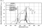
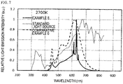
- Figs. 2 to 7 show the light emission spectra of the light emitting devices of Examples 1 to 6 with the spectra of the standard light sources.
- a light emitting device was produced to provide a correlated color temperature around 6,500 K in the same manner as in Example 1 except that the fourth fluorescent material was not used, but a combination of the chlorosilicate fluorescent material having a composition represented by the formula (VI) and a light emission peak wavelength of 521 nm, the first fluorescent material GYAG2, and the fifth fluorescent material SCASN was used as the fluorescent material, and the contents of the fluorescent materials were allowed to be the values shown in Table 3 below.
- Figs. 2 to 7 each show the light emission spectrum of each of the light emitting devices of Examples 1 to 6 and Comparative Examples 1 to 6, and the spectrum of the standard light source of each of the correlated color temperatures.
- the light emitting devices of Examples 1 to 6 emitted light having correlated color temperatures near correlated color temperatures of 6,500 K, 5,000 K, 4,000 K, 3,500 K, 3,000 K, and 2,700 K, respectively.
- the light emitting device of the present description can be applied to an illumination equipment excellent in light emission characteristics, an LED display, a flashlight of camera, and the like.
- the light emitting device can be favorably applied to an illumination equipment and a light source that are demanded to achieve a high light flux and a high color rendering property.
- the light emitting device can be used as a lightening fixture including the light emitting device.
Landscapes
- Chemical & Material Sciences (AREA)
- Inorganic Chemistry (AREA)
- Engineering & Computer Science (AREA)
- Materials Engineering (AREA)
- Organic Chemistry (AREA)
- Luminescent Compositions (AREA)
- Led Device Packages (AREA)
Applications Claiming Priority (3)
| Application Number | Priority Date | Filing Date | Title |
|---|---|---|---|
| JP2020056981 | 2020-03-27 | ||
| JP2021011944A JP7125631B2 (ja) | 2020-03-27 | 2021-01-28 | 発光装置及びそれを備えた灯具 |
| PCT/JP2021/005874 WO2021192743A1 (fr) | 2020-03-27 | 2021-02-17 | Dispositif électroluminescent et appareil d'éclairage pourvu dudit dispositif électroluminescent |
Publications (2)
| Publication Number | Publication Date |
|---|---|
| EP4131433A1 true EP4131433A1 (fr) | 2023-02-08 |
| EP4131433A4 EP4131433A4 (fr) | 2024-04-03 |
Family
ID=77892438
Family Applications (1)
| Application Number | Title | Priority Date | Filing Date |
|---|---|---|---|
| EP21774206.3A Pending EP4131433A4 (fr) | 2020-03-27 | 2021-02-17 | Dispositif électroluminescent et appareil d'éclairage pourvu dudit dispositif électroluminescent |
Country Status (6)
| Country | Link |
|---|---|
| US (1) | US20230151273A1 (fr) |
| EP (1) | EP4131433A4 (fr) |
| JP (1) | JP7311819B2 (fr) |
| CN (1) | CN115315821A (fr) |
| BR (1) | BR112022018956A2 (fr) |
| WO (1) | WO2021192743A1 (fr) |
Families Citing this family (2)
| Publication number | Priority date | Publication date | Assignee | Title |
|---|---|---|---|---|
| WO2023074525A1 (fr) * | 2021-10-28 | 2023-05-04 | 日亜化学工業株式会社 | Dispositif électroluminescent et dispositif de source lumineuse |
| CN117393549B (zh) * | 2023-09-18 | 2025-01-10 | 旭宇光电(深圳)股份有限公司 | 一种高光效全光谱半导体发光装置 |
Family Cites Families (16)
| Publication number | Priority date | Publication date | Assignee | Title |
|---|---|---|---|---|
| CN1203557C (zh) | 2000-05-29 | 2005-05-25 | 电灯专利信托有限公司 | 基于发光二极管的发射白光的照明设备 |
| DE10026435A1 (de) | 2000-05-29 | 2002-04-18 | Osram Opto Semiconductors Gmbh | Kalzium-Magnesium-Chlorosilikat-Leuchtstoff und seine Anwendung bei Lumineszenz-Konversions-LED |
| WO2012050199A1 (fr) * | 2010-10-15 | 2012-04-19 | 三菱化学株式会社 | Dispositif électroluminescent blanc et dispositif d'éclairage |
| JP6271301B2 (ja) * | 2013-03-04 | 2018-01-31 | シチズン電子株式会社 | 発光装置及び発光装置の製造方法 |
| JP2014177511A (ja) * | 2013-03-13 | 2014-09-25 | Toshiba Corp | 蛍光体、およびその製造方法、ならびにその蛍光体を用いた発光装置 |
| JP2014202266A (ja) | 2013-04-03 | 2014-10-27 | 新日鐵住金株式会社 | 高耐食性セルフタッピングねじ及びその製造方法 |
| JP2016188263A (ja) * | 2013-08-28 | 2016-11-04 | パナソニックIpマネジメント株式会社 | 蛍光体及びこれを用いた発光装置 |
| JP6524860B2 (ja) * | 2014-09-30 | 2019-06-05 | 日亜化学工業株式会社 | 発光装置 |
| JP2016154205A (ja) * | 2015-02-13 | 2016-08-25 | 日亜化学工業株式会社 | 発光装置 |
| JP6550889B2 (ja) * | 2015-04-22 | 2019-07-31 | 日亜化学工業株式会社 | 発光装置及びその製造方法 |
| US9871173B2 (en) * | 2015-06-18 | 2018-01-16 | Cree, Inc. | Light emitting devices having closely-spaced broad-spectrum and narrow-spectrum luminescent materials and related methods |
| JP6526603B2 (ja) * | 2015-06-30 | 2019-06-05 | 日亜化学工業株式会社 | 発光装置 |
| EP3347924A4 (fr) * | 2015-09-10 | 2019-04-10 | Intematix Corporation | Dispositifs électroluminescents à lumière blanche convertie au phosphore et composés de photoluminescence pour l'éclairage général et le rétro-éclairage d'affichage |
| JP6384468B2 (ja) * | 2015-12-22 | 2018-09-05 | 日亜化学工業株式会社 | 発光装置 |
| EP3893286B1 (fr) * | 2016-05-26 | 2023-01-18 | Nichia Corporation | Dispositif électroluminescent |
| JP6773018B2 (ja) * | 2017-12-26 | 2020-10-21 | 日亜化学工業株式会社 | 発光装置 |
-
2021
- 2021-02-17 CN CN202180022520.0A patent/CN115315821A/zh active Pending
- 2021-02-17 BR BR112022018956A patent/BR112022018956A2/pt unknown
- 2021-02-17 WO PCT/JP2021/005874 patent/WO2021192743A1/fr not_active Ceased
- 2021-02-17 EP EP21774206.3A patent/EP4131433A4/fr active Pending
- 2021-02-17 US US17/907,403 patent/US20230151273A1/en active Pending
-
2022
- 2022-07-29 JP JP2022121848A patent/JP7311819B2/ja active Active
Also Published As
| Publication number | Publication date |
|---|---|
| JP2022136300A (ja) | 2022-09-15 |
| WO2021192743A1 (fr) | 2021-09-30 |
| EP4131433A4 (fr) | 2024-04-03 |
| BR112022018956A2 (pt) | 2022-12-06 |
| CN115315821A (zh) | 2022-11-08 |
| JP7311819B2 (ja) | 2023-07-20 |
| US20230151273A1 (en) | 2023-05-18 |
Similar Documents
| Publication | Publication Date | Title |
|---|---|---|
| US10008643B2 (en) | Light emitting device having different types of phosphor material | |
| US9735323B2 (en) | Light emitting device having a triple phosphor fluorescent member | |
| US10026876B2 (en) | Light emitting device | |
| JP6526603B2 (ja) | 発光装置 | |
| EP2966147B1 (fr) | Matériau fluorescent et dispositif électroluminescent utilisant celui-ci | |
| WO2007120216A2 (fr) | Luminophores à base de nitrure à charge compensée pour applications d'éclairage | |
| JP6167913B2 (ja) | 蛍光体及びそれを用いた発光装置 | |
| JP6361549B2 (ja) | 蛍光体およびそれを用いた発光装置ならびに蛍光体の製造方法 | |
| KR101789856B1 (ko) | 청색 발광 형광체 및 그 청색 발광 형광체를 사용한 발광 장치 | |
| WO2006023100A1 (fr) | Del blanches à irc accordable | |
| EP1871857A1 (fr) | Phosphores rouges pour eclairage a base de del | |
| KR101042583B1 (ko) | 백색 형광체 및 백색 발광 소자 내지 장치 | |
| US8506104B1 (en) | Phosphors for LED lamps | |
| WO2008057225A2 (fr) | Lampes à diodes électroluminescentes à indice de rendu des couleurs élevé utilisant un seul phosphore | |
| US20060049414A1 (en) | Novel oxynitride phosphors | |
| JP2016154205A (ja) | 発光装置 | |
| JP6256541B2 (ja) | 発光装置 | |
| JP6520553B2 (ja) | 発光装置 | |
| EP4131433A1 (fr) | Dispositif électroluminescent et appareil d'éclairage pourvu dudit dispositif électroluminescent | |
| EP2770037A1 (fr) | Matériau à base de nitrure électroluminescent rouge et partie électroluminescente et dispositif électroluminescent le comprenant | |
| US9716212B2 (en) | Light emitting device | |
| JP6252396B2 (ja) | 蛍光体およびそれを用いた発光装置ならびに蛍光体の製造方法 | |
| JP7125631B2 (ja) | 発光装置及びそれを備えた灯具 | |
| JP7670965B2 (ja) | 発光装置及びそれを備えた灯具 | |
| JP2020084107A (ja) | ハロリン酸塩蛍光体及び発光装置 |
Legal Events
| Date | Code | Title | Description |
|---|---|---|---|
| STAA | Information on the status of an ep patent application or granted ep patent |
Free format text: STATUS: THE INTERNATIONAL PUBLICATION HAS BEEN MADE |
|
| PUAI | Public reference made under article 153(3) epc to a published international application that has entered the european phase |
Free format text: ORIGINAL CODE: 0009012 |
|
| STAA | Information on the status of an ep patent application or granted ep patent |
Free format text: STATUS: REQUEST FOR EXAMINATION WAS MADE |
|
| 17P | Request for examination filed |
Effective date: 20221025 |
|
| AK | Designated contracting states |
Kind code of ref document: A1 Designated state(s): AL AT BE BG CH CY CZ DE DK EE ES FI FR GB GR HR HU IE IS IT LI LT LU LV MC MK MT NL NO PL PT RO RS SE SI SK SM TR |
|
| DAV | Request for validation of the european patent (deleted) | ||
| DAX | Request for extension of the european patent (deleted) | ||
| A4 | Supplementary search report drawn up and despatched |
Effective date: 20240305 |
|
| RIC1 | Information provided on ipc code assigned before grant |
Ipc: C09K 11/80 20060101ALI20240228BHEP Ipc: C09K 11/61 20060101ALI20240228BHEP Ipc: H01L 33/50 20100101AFI20240228BHEP |
|
| STAA | Information on the status of an ep patent application or granted ep patent |
Free format text: STATUS: EXAMINATION IS IN PROGRESS |
|
| 17Q | First examination report despatched |
Effective date: 20241106 |
|
| REG | Reference to a national code |
Ref country code: DE Ref legal event code: R079 Free format text: PREVIOUS MAIN CLASS: H01L0033500000 Ipc: C09K0011610000 |
|
| RIC1 | Information provided on ipc code assigned before grant |
Ipc: C09K 11/61 20060101AFI20260325BHEP Ipc: H10H 20/851 20250101ALI20260325BHEP |
|
| GRAP | Despatch of communication of intention to grant a patent |
Free format text: ORIGINAL CODE: EPIDOSNIGR1 |
|
| STAA | Information on the status of an ep patent application or granted ep patent |
Free format text: STATUS: GRANT OF PATENT IS INTENDED |