EP4131478A1 - Lithiumionenbatterie - Google Patents
Lithiumionenbatterie Download PDFInfo
- Publication number
- EP4131478A1 EP4131478A1 EP21778801.7A EP21778801A EP4131478A1 EP 4131478 A1 EP4131478 A1 EP 4131478A1 EP 21778801 A EP21778801 A EP 21778801A EP 4131478 A1 EP4131478 A1 EP 4131478A1
- Authority
- EP
- European Patent Office
- Prior art keywords
- negative electrode
- active material
- positive electrode
- mixture layer
- electrode active
- Prior art date
- Legal status (The legal status is an assumption and is not a legal conclusion. Google has not performed a legal analysis and makes no representation as to the accuracy of the status listed.)
- Pending
Links
Images


Classifications
-
- H—ELECTRICITY
- H01—ELECTRIC ELEMENTS
- H01M—PROCESSES OR MEANS, e.g. BATTERIES, FOR THE DIRECT CONVERSION OF CHEMICAL ENERGY INTO ELECTRICAL ENERGY
- H01M4/00—Electrodes
- H01M4/02—Electrodes composed of, or comprising, active material
- H01M4/36—Selection of substances as active materials, active masses, active liquids
- H01M4/38—Selection of substances as active materials, active masses, active liquids of elements or alloys
- H01M4/387—Tin or alloys based on tin
-
- H—ELECTRICITY
- H01—ELECTRIC ELEMENTS
- H01M—PROCESSES OR MEANS, e.g. BATTERIES, FOR THE DIRECT CONVERSION OF CHEMICAL ENERGY INTO ELECTRICAL ENERGY
- H01M10/00—Secondary cells; Manufacture thereof
- H01M10/05—Accumulators with non-aqueous electrolyte
- H01M10/052—Li-accumulators
- H01M10/0525—Rocking-chair batteries, i.e. batteries with lithium insertion or intercalation in both electrodes; Lithium-ion batteries
-
- H—ELECTRICITY
- H01—ELECTRIC ELEMENTS
- H01M—PROCESSES OR MEANS, e.g. BATTERIES, FOR THE DIRECT CONVERSION OF CHEMICAL ENERGY INTO ELECTRICAL ENERGY
- H01M4/00—Electrodes
- H01M4/02—Electrodes composed of, or comprising, active material
- H01M4/13—Electrodes for accumulators with non-aqueous electrolyte, e.g. for lithium-accumulators; Processes of manufacture thereof
- H01M4/134—Electrodes based on metals, Si or alloys
-
- H—ELECTRICITY
- H01—ELECTRIC ELEMENTS
- H01M—PROCESSES OR MEANS, e.g. BATTERIES, FOR THE DIRECT CONVERSION OF CHEMICAL ENERGY INTO ELECTRICAL ENERGY
- H01M4/00—Electrodes
- H01M4/02—Electrodes composed of, or comprising, active material
- H01M4/62—Selection of inactive substances as ingredients for active masses, e.g. binders, fillers
- H01M4/621—Binders
- H01M4/622—Binders being polymers
-
- H—ELECTRICITY
- H01—ELECTRIC ELEMENTS
- H01M—PROCESSES OR MEANS, e.g. BATTERIES, FOR THE DIRECT CONVERSION OF CHEMICAL ENERGY INTO ELECTRICAL ENERGY
- H01M4/00—Electrodes
- H01M4/02—Electrodes composed of, or comprising, active material
- H01M2004/021—Physical characteristics, e.g. porosity, surface area
-
- H—ELECTRICITY
- H01—ELECTRIC ELEMENTS
- H01M—PROCESSES OR MEANS, e.g. BATTERIES, FOR THE DIRECT CONVERSION OF CHEMICAL ENERGY INTO ELECTRICAL ENERGY
- H01M4/00—Electrodes
- H01M4/02—Electrodes composed of, or comprising, active material
- H01M2004/026—Electrodes composed of, or comprising, active material characterised by the polarity
- H01M2004/027—Negative electrodes
-
- Y—GENERAL TAGGING OF NEW TECHNOLOGICAL DEVELOPMENTS; GENERAL TAGGING OF CROSS-SECTIONAL TECHNOLOGIES SPANNING OVER SEVERAL SECTIONS OF THE IPC; TECHNICAL SUBJECTS COVERED BY FORMER USPC CROSS-REFERENCE ART COLLECTIONS [XRACs] AND DIGESTS
- Y02—TECHNOLOGIES OR APPLICATIONS FOR MITIGATION OR ADAPTATION AGAINST CLIMATE CHANGE
- Y02E—REDUCTION OF GREENHOUSE GAS [GHG] EMISSIONS, RELATED TO ENERGY GENERATION, TRANSMISSION OR DISTRIBUTION
- Y02E60/00—Enabling technologies; Technologies with a potential or indirect contribution to GHG emissions mitigation
- Y02E60/10—Energy storage using batteries
Definitions
- the present disclosure generally relates to a lithium-ion battery which comprises a positive electrode having a positive electrode mixture layer including a positive electrode active material, and a negative electrode having a negative electrode mixture layer including a negative electrode active material, and in which charge and discharge are performed by lithium ions moving between the positive electrode and the negative electrode.
- Lithium-ion batteries in which charge and discharge are performed by lithium ions (Li ions) moving between a negative electrode and a positive electrode are widespread.
- a negative electrode active material of a negative electrode mixture layer in this lithium-ion battery a graphite-based material is commonly used.
- the graphite-based negative electrode active material may be used with Si, and in this case, change in volume during charge and discharge is large, capacity maintenance characteristics are likely to deteriorate, and the cost is relatively high.
- Patent Literature 1 describes that an alloy having a La 3 Co 2 Sn 7 -type crystalline structure is used as the negative electrode active material.
- Patent Literature 2 describes that a content of the binder is set to 0.5 mass% or more and 5.0 mass% or less.
- Patent Literature 1 employs polyvinylidene fluoride (PVdF) as the binder; however, as a result of an experiment, it has been found that the use of an alloy having a La 3 Co 2 Sn 7 -type crystalline structure as the negative electrode active material and the use of PVdF as the binder results in gelation of a mixture slurry used for forming a negative electrode mixture layer due to a reaction between both of the materials, leading to difficulty in application of the slurry.
- the particle size of the negative electrode active material needs to be increased. However, increasing the particle size of the negative electrode active material reduces the reactivity between the negative electrode active material and Li, leading to lowered capacity.
- the alloy having the La 3 Co 2 Sn 7 -type crystalline structure causes alloying reaction to form an impurity alloy, and in this case, cycle characteristics deteriorate.
- a lithium-ion battery is a lithium-ion battery, which includes a positive electrode having a positive electrode mixture layer including a positive electrode active material, and a negative electrode having a negative electrode mixture layer including a negative electrode active material, and in which charge and discharge are performed by lithium ions moving between the positive electrode and the negative electrode, wherein the negative electrode mixture layer includes a negative electrode active material represented by the general formula M 3 Me 2 X 7 , wherein M includes at least one selected from the group consisting of La, Ce, Ba, Sr, Zr, Ca, Mg, and Y; Me includes at least one selected from the group consisting of Ti, V, Cr, Nb, Mn, Ni, Fe, Co, and Cu; and X includes at least one selected from the group consisting of Ge, Si, Sn, Al, P, Sb, and B, and a binder including ammonium carboxymethyl cellulose (NH 4 -CMC).
- M includes at least one selected from the group consisting of La, Ce, Ba, Sr, Zr, Ca
- a lithium-ion battery is a lithium-ion battery, which includes a positive electrode having a positive electrode mixture layer including a positive electrode active material, and a negative electrode having a negative electrode mixture layer including a negative electrode active material, and in which charge and discharge are performed by lithium ions moving between the positive electrode and the negative electrode, wherein the negative electrode mixture layer includes a negative electrode active material represented by the general formula M 3 Me 2 X 7 , wherein M includes at least one selected from the group consisting of La, Sr, Ca, Mg, and Y; Me includes at least one selected from the group consisting of Mn, Ni, Fe, Co, and Cu; and X includes at least one selected from the group consisting of Ge, Si, Sn, Al, and B, and a binder including ammonium carboxymethyl cellulose (NH 4 -CMC).
- M includes at least one selected from the group consisting of La, Sr, Ca, Mg, and Y
- Me includes at least one selected from the group consisting of Mn, Ni, Fe,
- M includes at least one selected from the group consisting of La, Ce, Ba, Sr, Zr, Ca, Mg, and Y; Me includes at least one selected from the group consisting of Ti, V, Cr, Nb, Mn, Ni, Fe, Co, and Cu; and X includes at least one selected from the group consisting of Ge, Si, Sn, Al, P, Sb, and B, such as La 3 Ni 2 Sn 7 , as the negative electrode active material enables to apply the negative electrode mixture layer, and inhibits lowering of the capacity and deterioration of the cycle characteristics.
- using an aqueous binder enables inexpensive application.
- a negative electrode material of a lithium-ion battery is preferably a material satisfying a high energy density and low expansion.
- Such an intermetallic compound which occludes and releases Li with an intercalation reaction, has a low expansion coefficient, and is considered to achieve a longer lifetime.
- a binder having a cyano group for example polyacrylonitrile (PAN) may inhibit the gelation of the negative electrode mixture slurry.
- PAN polyacrylonitrile
- PAN is an organic binder, which requires an application operation using an organic solvent, and disables inexpensive application.
- polyimide (PI) and styrene-butadiene rubber/carboxymethyl cellulose sodium salt (SBR/Na-CMC) causes alloying reaction with the La 3 Ni 2 Sn 7 -type crystalline alloy, which is the negative electrode active material, and the cycle characteristics may deteriorate.
- FIG. 1 is a longitudinal sectional view of a cylindrical secondary battery 10 of an example of an embodiment.
- an electrode assembly 14 and a non-aqueous electrolyte are housed in an exterior housing body 15.
- the electrode assembly 14 has a wound structure in which a positive electrode 11 and a negative electrode 12 are wound with a separator 13 interposed therebetween.
- a non-aqueous solvent of the non-aqueous electrolyte organic solvent
- carbonates, lactones, ethers, ketones, esters, and the like may be used, and two or more of these solvents may be mixed to be used.
- a mixed solvent including a cyclic carbonate and a chain carbonate is preferably used.
- ethylene carbonate (EC), propylene carbonate (PC), butylene carbonate (BC), and the like may be used as the cyclic carbonate
- dimethyl carbonate (DMC), ethyl methyl carbonate (EMC), diethyl carbonate (DEC), and the like may be used as the chain carbonate.
- electrolyte salt in the non-aqueous electrolyte LiPF 6 , LiBF 4 , LiCF 3 SO 3 , and the like, and a mixture thereof may be used.
- An amount of the electrolyte salt dissolved in the non-aqueous solvent may be, for example, 0.5 to 2.0 mol/L.
- the sealing assembly 16 side will be described as “the upper side”
- the bottom side of the exterior housing body 15 will be described as “the lower side”.
- An opening end of the exterior housing body 15 is capped with the sealing assembly 16 to seal inside the secondary battery 10.
- Insulating plates 17 and 18 are provided on the upper and lower sides of the electrode assembly 14, respectively.
- a positive electrode lead 19 extends upward through a through hole of the insulating plate 17, and welded to the lower face of a filter 22, which is a bottom plate of the sealing assembly 16.
- a negative electrode lead 20 extends through a through hole of the insulating plate 18 toward the bottom side of the exterior housing body 15, and welded to a bottom inner face of the exterior housing body 15.
- the exterior housing body 15 becomes a negative electrode terminal.
- the negative electrode lead 20 When the negative electrode lead 20 is provided on the terminal end part, the negative electrode lead 20 extends through an outside of the insulating plate 18 toward the bottom side of the exterior housing body 15, and welded to the bottom inner face of the exterior housing body 15.
- the exterior housing body 15 is, for example, a bottomed cylindrical metallic exterior housing can.
- a gasket 27 is provided between the exterior housing body 15 and the sealing assembly 16 to achieve sealability inside the secondary battery 10.
- the exterior housing body 15 has a grooved part 21 formed by, for example, pressing the side part thereof from the outside to support the sealing assembly 16.
- the grooved part 21 is preferably formed in a circular shape along a circumferential direction of the exterior housing body 15, and supports the sealing assembly 16 with the gasket 27 interposed therebetween and with the upper face of the grooved part 21.
- the sealing assembly 16 has the filter 22, a lower vent member 23, an insulating member 24, an upper vent member 25, and the cap 26 which are stacked in this order from the electrode assembly 14 side.
- Each member constituting the sealing assembly 16 has, for example, a disk shape or a ring shape, and each member except for the insulating member 24 is electrically connected each other.
- the lower vent member 23 and the upper vent member 25 are connected each other at each of central parts thereof, and the insulating member 24 is interposed between each of the circumferential parts of the vent members 23 and 25.
- the lower vent member 23 breaks and thereby the upper vent member 25 expands toward the cap 26 side to be separated from the lower vent member 23, resulting in cutting off of an electrical connection between both the members. If the internal pressure further increases, the upper vent member 25 breaks, and gas is discharged through an opening 26a of the cap 26.
- the positive electrode 11, negative electrode 12, and separator 13, which constitute the electrode assembly 14, particularly the negative electrode active material constituting the negative electrode 12 will be described.
- the positive electrode 11 has a positive electrode core and a positive electrode mixture layer provided on a surface of the positive electrode core.
- a foil of a metal stable within a potential range of the positive electrode 11, such as aluminum, a film in which such a metal is disposed on a surface layer thereof, and the like may be used.
- a thickness of the positive electrode core is, for example, 10 ⁇ m to 30 ⁇ m.
- the positive electrode mixture layer includes a positive electrode active material, a binder, and a conductive agent, and is preferably provided on both surfaces of the positive electrode core except for a portion to which the positive electrode lead 19 is connected.
- the positive electrode 11 may be produced by, for example, applying a positive electrode mixture slurry including the positive electrode active material, the binder, the conductive agent, and the like on the surface of the positive electrode core, drying and subsequently compressing the applied film to form the positive electrode mixture layer on both the surfaces of the positive electrode core.
- the positive electrode active material includes a lithium-transition metal oxide as a main component.
- the positive electrode active material may be constituted of substantially only the lithium-transition metal oxide, and particles of an inorganic compound, such as aluminum oxide and a lanthanoid-containing compound, may be adhered to a particle surface of the lithium-transition metal oxide.
- the lithium-transition metal oxide may be used singly, or may be used in combination of two or more thereof.
- Examples of a metal element contained in the lithium-transition metal oxide include nickel (Ni), cobalt (Co), manganese (Mn), aluminum (Al), boron (B), magnesium (Mg), titanium (Ti), vanadium (V), chromium (Cr), iron (Fe), copper (Cu), zinc (Zn), gallium (Ga), strontium (Sr), zirconium (Zr), niobium (Nb), indium (In), tin (Sn), tantalum (Ta), and tungsten (W).
- a preferable example of the lithium-transition metal oxide is a composite oxide represented by the general formula: Li a Ni x M (1-x) O 2 (0.1 ⁇ ⁇ ⁇ 1.2, 0.3 ⁇ x ⁇ 1, and M includes at least one of the group consisting of Co, Mn, and Al).
- M includes at least one of the group consisting of Co, Mn, and Al.
- NCA in which some nickel is substituted with cobalt and an aluminum is added, and the like is used, for example.
- Examples of the conductive agent included in the positive electrode mixture layer may include a carbon material such as carbon black, acetylene black, Ketjenblack, carbon nanotube, carbon nanofiber, and graphite.
- Examples of the binder included in the positive electrode mixture layer may include a fluororesin such as polytetrafluoroethylene (PTFE) and polyvinylidene fluoride (PVdF), polyacrylonitrile (PAN), a polyimide resin, an acrylic resin, and a polyolefin resin. With these resins, cellulose derivatives such as carboxymethyl cellulose (CMC) or a salt thereof, polyethylene oxide (PEO), and the like may be used in combination.
- the negative electrode 12 has a negative electrode core and a negative electrode mixture layer provided on a surface of the negative electrode core.
- a foil of a metal stable within a potential range of the negative electrode 12, such as copper, a film in which such a metal is disposed on a surface layer thereof, and the like may be used.
- a thickness of the negative electrode core is, for example, 5 ⁇ m to 15 ⁇ m.
- the negative electrode mixture layer includes a negative electrode active material and a binder, and is preferably provided on, for example, both surfaces of the negative electrode core except for a portion to which the negative electrode lead 20 is connected.
- the negative electrode 12 may be produced by, for example, applying a negative electrode mixture slurry including the negative electrode active material, the binder, and the like on the surface of the negative electrode core, drying and subsequently compressing the applied film to form the negative electrode mixture layer on both the surfaces of the negative electrode core.
- a conductive agent may be added into the negative electrode mixture slurry.
- the conductive agent may uniform a conductive path.
- the negative electrode mixture layer may include a conductive agent such as acetylene black similar to that in the positive electrode mixture layer.
- the negative electrode mixture layer includes, as the negative electrode active material, an intermetallic compound (a M 3 Me 2 X 7 -type crystalline alloy) represented by the general formula M 3 Me 2 X 7 , wherein M includes at least one of the group consisting of La and Ca; Me includes at least one of the group consisting of Mn, Ni, Fe, and Co; and X includes at least one of the group consisting of Ge, Si, Sn, and Al.
- M includes at least one of the group consisting of La and Ca
- Me includes at least one of the group consisting of Mn, Ni, Fe, and Co
- X includes at least one of the group consisting of Ge, Si, Sn, and Al.
- preferable negative electrode active materials include La 3 Co 2 Sn 7 , La 3 Mn 2 Sn 7 , and La 3 Ni 2 Sn 7 .
- La 3 Co 2 Sn 7 or La 3 Ni 2 Sn 7 is preferable, and La 3 Ni 2 Sn 7 is particularly preferable from the viewpoint of increase in the capacity.
- a particle diameter of M 3 Me 2 X 7 which is the negative electrode active material, is preferably 1 to 30 ⁇ m, more preferably 2 to 20 ⁇ m, and particularly preferably 2 to 10 ⁇ m.
- An excessively larger particle diameter of M 3 Me 2 X 7 lowers reactivity with Li, and decreases a contacting area between the particles to increase the resistance. Meanwhile, an excessively smaller particle diameter is presumed to lower a filling density of the negative electrode active material to decrease the capacity.
- An average particle diameter of M 3 Me 2 X 7 is, for example, 3 to 15 ⁇ m or 5 to 10 ⁇ m.
- the particle diameter of M 3 Me 2 X 7 is measured as a diameter of a circumscribed circle of M 3 Me 2 X 7 particle in a cross-sectional image of the negative electrode mixture layer observed with a scanning electron microscope (SEM).
- SEM scanning electron microscope
- the intermetallic compound represented by M 3 Me 2 X 7 may be formed by ark melting, and annealing is preferably performed after the ark melting. With M, up to approximately 50% of La may be substituted. For example, with approximately 40% of La substituted with Ca, a large charge-discharge capacity (a first charge capacity of 301 mAh/g, a first discharge capacity of 223 mAh/g (1718 mAh/cc)) and a small rate of change in volume (0.5% or less) were obtained.
- the negative electrode active material includes M 3 Me 2 X 7 as a main component (component having the highest mass ratio), and may be composed of substantially only M 3 Me 2 X 7 .
- another active material such as an intermetallic compound other than M 3 Me 2 X 7 , a carbon-based active material such as graphite, or Si-based active material containing Si may be used in combination.
- a content of the graphite may be, for example, 50 to 90 mass% based on a mass of the negative electrode active material.
- a binder including an aqueous ammonium carboxymethyl cellulose (NH 4 -CMC) is used.
- the binder preferably further includes styrene-butadiene rubber (SBR).
- SBR styrene-butadiene rubber
- Aqueous binders such as aqueous urethanes and aqueous acrylic polymers may also be used.
- a mass ratio of the binder to the negative electrode active material is preferably 0.3 wt% or more and 5.0 wt% or less.
- a ratio between NH 4 -CMC and SBR is preferably approximately 2:0.5 to 2.
- a porous sheet having an ion permeation property and an insulation property is used.
- the porous sheet include a fine porous film, a woven fabric, and a nonwoven fabric.
- a preferable material of the separator 13 is polyolefin resins such as polyethylene and polypropylene, cellulose, and the like.
- the separator 13 may have any of a single-layered structure and a multilayered structure.
- a heat-resistant layer including a heat-resistant material may be formed on a surface of the separator 13, a heat-resistant layer including a heat-resistant material may be formed.
- the heat-resistant material may include polyamide resins such as an aliphatic polyamide and an aromatic polyamide (aramid), and polyimide resins such as a polyamideimide and a polyimide.
- La 3 Ni 2 Sn 7 having a particle diameter of 2 to 20 ⁇ m was used as a negative electrode active material, SRB/CMC was used as a binder, and an artificial graphite SP5030 was used as a conductive agent.
- La 3 Ni 2 Sn 7 /NH 4 -CMC/SBR/SP5030 were mixed at a mass ratio of 85.5/3/1.5/10 to prepare a negative electrode mixture slurry. Then, the negative electrode mixture slurry was applied on a negative electrode core composed of a copper foil, the applied film was dried and compressed, and then cut to a predetermined electrode size to obtain a negative electrode.
- a foil having a roughened surface and a thickness of approximately 18 ⁇ m may be used.
- the above negative electrode and a positive electrode composed of a lithium metal foil were disposed opposite to each other with a separator interposed therebetween to constitute an electrode assembly, and the electrode assembly was housed in an exterior housing can.
- a predetermined non-aqueous electrolyte liquid was injected into the exterior housing can, and then the exterior housing can was sealed to obtain a bipolar cell (non-aqueous electrolyte secondary battery).
- the electrolyte liquid was EC/EMC solvent into which 1.0 M of LiPF 6 was added as the electrolyte.
- the obtained test cell was charged under an environment at normal temperature at a constant current (CC) of 0.2 C until, as a battery voltage of, charge of 0.01 V (a negative electrode potential was 0.01 V with respect to the metal lithium) and discharge of 1.5 V (a negative electrode potential was 1.5 V with respect to the metal lithium) to determine a change in the electrode voltage. Then, the charge-discharge cycles in which the test cell was discharged at a constant current and charged at a constant current again were repeated to measure a charge capacity and discharge capacity at each cycle.
- CC constant current
- FIG. 2 shows X-ray diffraction patterns of electrodes in: Example, which uses styrene-butadiene rubber/ammonium carboxymethyl cellulose (SBR/NH 4 -CMC) as the binder; Comparative Example 1, which uses styrene-butadiene rubber/sodium carboxymethyl cellulose (SBR/Na-CMC); Comparative Example 2, which uses PAN; Comparative Example 3, which uses PI; and Comparative Example 4, which uses PVdF.
- peaks shown as ⁇ are peaks of an impurity alloy (an impurity alloy generated by an unnecessary alloying reaction).
- Example, which uses SBR/NH 4 -CMC is found to generate no phase of the impurity alloy.
- FIG. 3A and FIG. 3B are graphs indicating the charge-discharge characteristics in Example.
- FIG. 3A is a graph indicating a relationship between the capacity and the electrode potential
- FIG. 3B is a graph indicating a relationship between the number of cycles and the capacity.
- Example where SBR/NH 4 -CMC is used as the negative electrode binder, almost no deterioration is found in the three times of charges and discharges. Even with 29 charge-discharge cycles, the test cell in Example has little change in the charge-discharge curve, maintains 99.5% of the initial charge-discharge capacity, and has good cycle characteristics.
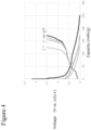
- FIG. 4 is a view indicating the charge-discharge characteristics in Comparative Example 1, which uses SBR/Na-CMC as the negative electrode binder. As shown, in Comparative Example 1, the capacity is lowered by repeating charge and discharge, and it is found to have poor cycle characteristics. This is presumably because of occurrence of the alloying reaction shown in FIG. 2 .
- Table 1 is a table showing evaluation of the binders with respect to each negative electrode active material of La 3 Ni 2 Sn 7 and La 1.8 Ca 1.2 Ni 2 Sn 7 .
- Table 1 PVdF PAN PI SBR/CMC Na-CMC NH 4 -CMC La 3 Ni 2 Sn 7 ⁇ 1 ⁇ 2 ⁇ 3 ⁇ 3 ⁇ La 1.8 Ca 1.2 Ni 2 Sn 7 ⁇ 1 ⁇ 2 ⁇ 3 ⁇ ⁇
- the negative electrode mixture layer including any of La 3 Ni 2 Sn 7 and La 1.8 Ca 1.2 Ni 2 Sn 7 gave the same result. That is, PVdF is likely to proceed gelation during the application, and use thereof requires being devised ( ⁇ 1 ). The gelation during the application may be inhibited by adding maleic anhydride. PAN, which requires using an organic solvent, increases a manufacturing cost ( ⁇ 2 ). PI and SBR/Na-CMC, which generate an alloy during the application, deteriorate the cycle characteristics ( ⁇ 3 ). In Example, SBR/NH 4 -CMC, which is aqueous and does not require an organic solvent, generates no alloy, yields the good cycle characteristics, and is preferable as the binder (C).
- the negative electrode mixture layer including the negative electrode active material represented by the general formula M 3 Me 2 X 7 , wherein M includes at least one selected from the group consisting of La, Sr, Ca, Mg, and Y; Me includes at least one selected from the group consisting of Mn, Ni, Fe, Co, and Cu; and X includes at least one selected from the group consisting of Ge, Si, Sn, Al, and B, it has been confirmed that the binder including ammonium carboxymethyl cellulose (NH 4 -CMC) is preferable.
- M includes at least one selected from the group consisting of La, Sr, Ca, Mg, and Y
- Me includes at least one selected from the group consisting of Mn, Ni, Fe, Co, and Cu
- X includes at least one selected from the group consisting of Ge, Si, Sn, Al, and B
- M includes at least one selected from the group consisting of La, Ce, Ba, Sr, Zr, Ca, Mg, and Y; Me includes at least one selected from the group consisting of Ti, V, Cr, Nb, Mn, Ni, Fe, Co, and Cu; and X includes at least one selected from the group consisting of Ge, Si, Sn, Al, P, Sb, and B, it is found that the binder including ammonium carboxymethyl cellulose (NH 4 -CMC) is preferable.
- NH 4 -CMC ammonium carboxymethyl cellulose
Landscapes
- Chemical & Material Sciences (AREA)
- Chemical Kinetics & Catalysis (AREA)
- Electrochemistry (AREA)
- General Chemical & Material Sciences (AREA)
- Engineering & Computer Science (AREA)
- Materials Engineering (AREA)
- Manufacturing & Machinery (AREA)
- Battery Electrode And Active Subsutance (AREA)
Applications Claiming Priority (2)
| Application Number | Priority Date | Filing Date | Title |
|---|---|---|---|
| JP2020066991 | 2020-04-02 | ||
| PCT/JP2021/013499 WO2021200924A1 (ja) | 2020-04-02 | 2021-03-30 | リチウムイオン電池 |
Publications (2)
| Publication Number | Publication Date |
|---|---|
| EP4131478A1 true EP4131478A1 (de) | 2023-02-08 |
| EP4131478A4 EP4131478A4 (de) | 2023-09-27 |
Family
ID=77928948
Family Applications (1)
| Application Number | Title | Priority Date | Filing Date |
|---|---|---|---|
| EP21778801.7A Pending EP4131478A4 (de) | 2020-04-02 | 2021-03-30 | Lithiumionenbatterie |
Country Status (5)
| Country | Link |
|---|---|
| US (1) | US12580187B2 (de) |
| EP (1) | EP4131478A4 (de) |
| JP (1) | JP7599138B2 (de) |
| CN (1) | CN115362574B (de) |
| WO (1) | WO2021200924A1 (de) |
Family Cites Families (7)
| Publication number | Priority date | Publication date | Assignee | Title |
|---|---|---|---|---|
| JP4346395B2 (ja) * | 2003-09-24 | 2009-10-21 | 株式会社東芝 | 非水電解質二次電池 |
| JP4127692B2 (ja) * | 2004-03-23 | 2008-07-30 | 株式会社東芝 | 非水電解質二次電池 |
| JP4202350B2 (ja) * | 2005-09-05 | 2008-12-24 | 株式会社東芝 | 非水電解質電池 |
| JP2007258127A (ja) | 2006-03-27 | 2007-10-04 | Sony Corp | 負極および電池 |
| JP2010218855A (ja) | 2009-03-17 | 2010-09-30 | Sanyo Electric Co Ltd | 非水電解質二次電池用負極及び非水電解質二次電池 |
| JP6664184B2 (ja) * | 2014-10-15 | 2020-03-13 | 株式会社半導体エネルギー研究所 | 電極、及び電極の作製方法 |
| US20230100030A1 (en) | 2020-02-28 | 2023-03-30 | Panasonic Intellectual Property Management Co., Ltd. | Lithium ion battery |
-
2021
- 2021-03-30 US US17/915,055 patent/US12580187B2/en active Active
- 2021-03-30 WO PCT/JP2021/013499 patent/WO2021200924A1/ja not_active Ceased
- 2021-03-30 JP JP2022512280A patent/JP7599138B2/ja active Active
- 2021-03-30 CN CN202180025296.0A patent/CN115362574B/zh active Active
- 2021-03-30 EP EP21778801.7A patent/EP4131478A4/de active Pending
Also Published As
| Publication number | Publication date |
|---|---|
| CN115362574B (zh) | 2025-08-29 |
| JPWO2021200924A1 (de) | 2021-10-07 |
| US12580187B2 (en) | 2026-03-17 |
| JP7599138B2 (ja) | 2024-12-13 |
| WO2021200924A1 (ja) | 2021-10-07 |
| EP4131478A4 (de) | 2023-09-27 |
| CN115362574A (zh) | 2022-11-18 |
| US20230163285A1 (en) | 2023-05-25 |
Similar Documents
| Publication | Publication Date | Title |
|---|---|---|
| US12573623B2 (en) | Nonaqueous electrolyte secondary battery | |
| EP4398372A1 (de) | Sekundärbatterie mit nichtwässrigem elektrolyten | |
| CN112204767B (zh) | 非水电解质二次电池 | |
| EP3876332A1 (de) | Sekundärbatterie | |
| US12347855B2 (en) | Negative electrode active material for nonaqueous electrolyte secondary batteries, and nonaqueous electrolyte secondary battery | |
| US12166207B2 (en) | Positive electrode active material for nonaqueous electrolyte secondary batteries, and nonaqueous electrolyte secondary battery | |
| US20220278323A1 (en) | Non-aqueous electrolyte secondary battery | |
| EP4625678A1 (de) | Zylindrische sekundärbatterie mit nichtwässrigem elektrolyten | |
| EP4398332B1 (de) | Negativelektrode für sekundärbatterie und sekundärbatterie | |
| US20230100030A1 (en) | Lithium ion battery | |
| US12580187B2 (en) | Lithium ion battery | |
| CN115023824B (zh) | 锂离子电池 | |
| US20220320490A1 (en) | Positive electrode active material for nonaqueous electrolyte secondary battery, and nonaqueous electrolyte secondary battery | |
| EP4475214A1 (de) | Lithiumionenbatterie | |
| US12362353B2 (en) | Negative electrode active material for nonaqueous electrolyte secondary batteries, and nonaqueous electrolyte secondary battery | |
| US20250015267A1 (en) | Nonaqueous electrolyte secondary battery positive electrode and nonaqueous electrolyte secondary battery | |
| US20200067094A1 (en) | Nonaqueous electrolyte secondary battery | |
| US12300815B2 (en) | Positive electrode active material for nonaqueous electrolyte secondary batteries, and nonaqueous electrolyte secondary battery | |
| EP4625680A1 (de) | Zylindrische sekundärbatterie mit nichtwässrigem elektrolyten | |
| US20250192154A1 (en) | Positive electrode for non-aqueous electrolyte secondary battery, and non-aqueous electrolyte secondary battery | |
| EP4379895A1 (de) | Sekundärbatterie mit nichtwässrigem elektrolyten | |
| EP4269360A1 (de) | Positivelektrodenaktivmaterial für sekundärbatterien mit wasserfreiem elektrolyt und sekundärbatterie mit wasserfreiem elektrolyt | |
| US20230335717A1 (en) | Non-aqueous electrolyte secondary battery |
Legal Events
| Date | Code | Title | Description |
|---|---|---|---|
| STAA | Information on the status of an ep patent application or granted ep patent |
Free format text: STATUS: THE INTERNATIONAL PUBLICATION HAS BEEN MADE |
|
| PUAI | Public reference made under article 153(3) epc to a published international application that has entered the european phase |
Free format text: ORIGINAL CODE: 0009012 |
|
| STAA | Information on the status of an ep patent application or granted ep patent |
Free format text: STATUS: REQUEST FOR EXAMINATION WAS MADE |
|
| 17P | Request for examination filed |
Effective date: 20220922 |
|
| AK | Designated contracting states |
Kind code of ref document: A1 Designated state(s): AL AT BE BG CH CY CZ DE DK EE ES FI FR GB GR HR HU IE IS IT LI LT LU LV MC MK MT NL NO PL PT RO RS SE SI SK SM TR |
|
| DAV | Request for validation of the european patent (deleted) | ||
| DAX | Request for extension of the european patent (deleted) | ||
| A4 | Supplementary search report drawn up and despatched |
Effective date: 20230824 |
|
| RIC1 | Information provided on ipc code assigned before grant |
Ipc: H01M 4/62 20060101ALI20230818BHEP Ipc: H01M 4/134 20100101AFI20230818BHEP |