EP4131502A1 - Festelektrolytmaterial, batterie damit und verfahren zur herstellung eines festelektrolytmaterials - Google Patents
Festelektrolytmaterial, batterie damit und verfahren zur herstellung eines festelektrolytmaterials Download PDFInfo
- Publication number
- EP4131502A1 EP4131502A1 EP21779961.8A EP21779961A EP4131502A1 EP 4131502 A1 EP4131502 A1 EP 4131502A1 EP 21779961 A EP21779961 A EP 21779961A EP 4131502 A1 EP4131502 A1 EP 4131502A1
- Authority
- EP
- European Patent Office
- Prior art keywords
- solid electrolyte
- electrolyte material
- material according
- examples
- smcl
- Prior art date
- Legal status (The legal status is an assumption and is not a legal conclusion. Google has not performed a legal analysis and makes no representation as to the accuracy of the status listed.)
- Withdrawn
Links
Images




Classifications
-
- H—ELECTRICITY
- H01—ELECTRIC ELEMENTS
- H01M—PROCESSES OR MEANS, e.g. BATTERIES, FOR THE DIRECT CONVERSION OF CHEMICAL ENERGY INTO ELECTRICAL ENERGY
- H01M10/00—Secondary cells; Manufacture thereof
- H01M10/05—Accumulators with non-aqueous electrolyte
- H01M10/056—Accumulators with non-aqueous electrolyte characterised by the materials used as electrolytes, e.g. mixed inorganic/organic electrolytes
- H01M10/0561—Accumulators with non-aqueous electrolyte characterised by the materials used as electrolytes, e.g. mixed inorganic/organic electrolytes the electrolyte being constituted of inorganic materials only
- H01M10/0562—Solid materials
-
- C—CHEMISTRY; METALLURGY
- C01—INORGANIC CHEMISTRY
- C01F—COMPOUNDS OF THE METALS BERYLLIUM, MAGNESIUM, ALUMINIUM, CALCIUM, STRONTIUM, BARIUM, RADIUM, THORIUM, OR OF THE RARE-EARTH METALS
- C01F17/00—Compounds of rare earth metals
- C01F17/30—Compounds containing rare earth metals and at least one element other than a rare earth metal, oxygen or hydrogen, e.g. La4S3Br6
- C01F17/36—Compounds containing rare earth metals and at least one element other than a rare earth metal, oxygen or hydrogen, e.g. La4S3Br6 halogen being the only anion, e.g. NaYF4
-
- H—ELECTRICITY
- H01—ELECTRIC ELEMENTS
- H01B—CABLES; CONDUCTORS; INSULATORS; SELECTION OF MATERIALS FOR THEIR CONDUCTIVE, INSULATING OR DIELECTRIC PROPERTIES
- H01B1/00—Conductors or conductive bodies characterised by the conductive materials; Selection of materials as conductors
- H01B1/06—Conductors or conductive bodies characterised by the conductive materials; Selection of materials as conductors mainly consisting of other non-metallic substances
-
- H—ELECTRICITY
- H01—ELECTRIC ELEMENTS
- H01M—PROCESSES OR MEANS, e.g. BATTERIES, FOR THE DIRECT CONVERSION OF CHEMICAL ENERGY INTO ELECTRICAL ENERGY
- H01M10/00—Secondary cells; Manufacture thereof
- H01M10/05—Accumulators with non-aqueous electrolyte
- H01M10/052—Li-accumulators
-
- H—ELECTRICITY
- H01—ELECTRIC ELEMENTS
- H01M—PROCESSES OR MEANS, e.g. BATTERIES, FOR THE DIRECT CONVERSION OF CHEMICAL ENERGY INTO ELECTRICAL ENERGY
- H01M10/00—Secondary cells; Manufacture thereof
- H01M10/05—Accumulators with non-aqueous electrolyte
- H01M10/052—Li-accumulators
- H01M10/0525—Rocking-chair batteries, i.e. batteries with lithium insertion or intercalation in both electrodes; Lithium-ion batteries
-
- H—ELECTRICITY
- H01—ELECTRIC ELEMENTS
- H01M—PROCESSES OR MEANS, e.g. BATTERIES, FOR THE DIRECT CONVERSION OF CHEMICAL ENERGY INTO ELECTRICAL ENERGY
- H01M4/00—Electrodes
- H01M4/02—Electrodes composed of, or comprising, active material
- H01M4/62—Selection of inactive substances as ingredients for active masses, e.g. binders, fillers
-
- H—ELECTRICITY
- H01—ELECTRIC ELEMENTS
- H01M—PROCESSES OR MEANS, e.g. BATTERIES, FOR THE DIRECT CONVERSION OF CHEMICAL ENERGY INTO ELECTRICAL ENERGY
- H01M6/00—Primary cells; Manufacture thereof
- H01M6/14—Cells with non-aqueous electrolyte
- H01M6/18—Cells with non-aqueous electrolyte with solid electrolyte
-
- C—CHEMISTRY; METALLURGY
- C01—INORGANIC CHEMISTRY
- C01P—INDEXING SCHEME RELATING TO STRUCTURAL AND PHYSICAL ASPECTS OF SOLID INORGANIC COMPOUNDS
- C01P2002/00—Crystal-structural characteristics
- C01P2002/50—Solid solutions
-
- C—CHEMISTRY; METALLURGY
- C01—INORGANIC CHEMISTRY
- C01P—INDEXING SCHEME RELATING TO STRUCTURAL AND PHYSICAL ASPECTS OF SOLID INORGANIC COMPOUNDS
- C01P2002/00—Crystal-structural characteristics
- C01P2002/70—Crystal-structural characteristics defined by measured X-ray, neutron or electron diffraction data
- C01P2002/72—Crystal-structural characteristics defined by measured X-ray, neutron or electron diffraction data by d-values or two theta-values, e.g. as X-ray diagram
-
- C—CHEMISTRY; METALLURGY
- C01—INORGANIC CHEMISTRY
- C01P—INDEXING SCHEME RELATING TO STRUCTURAL AND PHYSICAL ASPECTS OF SOLID INORGANIC COMPOUNDS
- C01P2006/00—Physical properties of inorganic compounds
- C01P2006/40—Electric properties
-
- H—ELECTRICITY
- H01—ELECTRIC ELEMENTS
- H01M—PROCESSES OR MEANS, e.g. BATTERIES, FOR THE DIRECT CONVERSION OF CHEMICAL ENERGY INTO ELECTRICAL ENERGY
- H01M2300/00—Electrolytes
- H01M2300/0017—Non-aqueous electrolytes
- H01M2300/0065—Solid electrolytes
- H01M2300/0068—Solid electrolytes inorganic
- H01M2300/008—Halides
-
- Y—GENERAL TAGGING OF NEW TECHNOLOGICAL DEVELOPMENTS; GENERAL TAGGING OF CROSS-SECTIONAL TECHNOLOGIES SPANNING OVER SEVERAL SECTIONS OF THE IPC; TECHNICAL SUBJECTS COVERED BY FORMER USPC CROSS-REFERENCE ART COLLECTIONS [XRACs] AND DIGESTS
- Y02—TECHNOLOGIES OR APPLICATIONS FOR MITIGATION OR ADAPTATION AGAINST CLIMATE CHANGE
- Y02E—REDUCTION OF GREENHOUSE GAS [GHG] EMISSIONS, RELATED TO ENERGY GENERATION, TRANSMISSION OR DISTRIBUTION
- Y02E60/00—Enabling technologies; Technologies with a potential or indirect contribution to GHG emissions mitigation
- Y02E60/10—Energy storage using batteries
Definitions
- the present disclosure relates to a solid electrolyte material, a battery using the same, and a method of manufacturing a solid electrolyte material.
- Patent Literature 1 discloses an all-solid-state battery using a sulfide solid electrolyte.
- the present disclosure aims to provide a novel solid electrolyte material having high utility.
- a solid electrolyte material of the present disclosure includes:
- the present disclosure provides a novel solid electrolyte material having high utility.
- a solid electrolyte material according to a first embodiment includes Li, DC, Y, Sm, and X.
- DC is at least one selected from the group consisting of Mg, Ca, Sr, Ba, and Zn.
- X is at least one selected from the group consisting of F, Cl, Br, and I.
- the solid electrolyte material according to the first embodiment can have, for example, practical lithium-ion conductivity, and can have, for example, high lithium-ion conductivity.
- high lithium-ion conductivity is, for example, 1 ⁇ 10 -5 S/cm or more near room temperature.
- the solid electrolyte material according to the first embodiment can have an ionic conductivity of, for example, 1 ⁇ 10 -5 S/cm or more.
- the solid electrolyte material according to the first embodiment can be used to achieve a battery having excellent charge and discharge characteristics.
- An example of the battery is an all-solid-state battery.
- the all-solid-state battery may be a primary battery or a secondary battery.
- the solid electrolyte material according to the first embodiment should be substantially free of sulfur.
- the phrase "the solid electrolyte material according to the first embodiment is substantially free of sulfur” means that the solid electrolyte material does not contain sulfur as a constituent element except sulfur inevitably introduced as impurities. In this case, sulfur introduced as impurities into the solid electrolyte material has an amount of, for example, 1 mol% or less. It is further desirable that the solid electrolyte material according to the first embodiment should be free of sulfur. Solid electrolyte materials free of sulfur generate no hydrogen sulfide when exposed to the atmosphere, and accordingly are excellent in safety. The sulfide solid electrolyte disclosed in Patent Literature 1 might generate hydrogen sulfide when exposed to the atmosphere.
- the solid electrolyte material according to the first embodiment may consist substantially of Li, DC, Y, Sm, and X.
- the phrase "the solid electrolyte material according to the first embodiment consists substantially of Li, DC, Y, Sm, and X" means that the ratio (i.e., mole fraction) of the sum of amounts of substance of Li, DC, Y, Sm, and X to the total of amounts of substance of all the elements constituting the solid electrolyte material according to the first embodiment is 90% or more. In an example, the ratio may be 95% or more.
- the solid electrolyte material according to the first embodiment may consist of Li, DC, Y, Sm, and X.
- the solid electrolyte material according to the first embodiment may contain an element which is inevitably introduced.
- the element include hydrogen, oxygen, and nitrogen.
- Such an element may be present in a raw material powder of the solid electrolyte material or in an atmosphere for manufacturing or storing the solid electrolyte material.
- X may be at least one selected from the group consisting of Cl and Br.
- DC may be Ca.
- the solid electrolyte material according to the first embodiment may be a material represented by the following composition formula (1), Li 3-2a-3d DC a Y 1-b Sm b+d Br 6-c Cl c ... (1) where the following four mathematical relations are satisfied: 0 ⁇ a ⁇ 0.25 ; 0 ⁇ b ⁇ 1 ; 0 ⁇ c ⁇ 6 ; and 0 ⁇ d ⁇ 0.05 .
- the material represented by the composition formula (1) has high ionic conductivity.
- the upper and lower limits for the range of a in the composition formula (1) may be defined by any combination of numerical values selected from numerical values greater than 0 (i.e., 0 ⁇ a) and numerical values 0.01, 0.1, 0.15, 0.125, 0.15, and 0.25.
- the upper and lower limits for the range of b in the composition formula (1) may be defined by any combination of numerical values selected from numerical values greater than 0 and numerical values 0.01, 0.1, 0.15, 0.2, 0.3, 0.5, 0.7, 0.9, and less than 1 (i.e., b ⁇ 1).
- the upper and lower limits for the range of c in the composition formula (1) may be defined by any combination of numerical values selected from numerical values 0, 1.5, 2.5, 3, 3.5, 4, 4.5, 5, and 6.
- An X-ray diffraction pattern of the solid electrolyte material according to the first embodiment can be obtained by X-ray diffraction measurement according to the ⁇ -2 ⁇ method using Cu-K ⁇ rays (wavelengths of 1.5405 ⁇ and 1.5444 ⁇ , i.e., wavelengths of 0.15405 nm and 0.15444 nm).
- at least one peak may be present within a range of a diffraction angle 2 ⁇ from 29.0° to 32.0°, and at least two peaks may be present within a range of the diffraction angle 2 ⁇ from 14.0° to 18.0°.
- a crystalline phase having such a peak is referred to as first crystalline phase.
- a solid electrolyte material including the first crystalline phase has high ionic conductivity. The solid electrolyte material including the first crystalline phase facilitates formation of a path for lithium ions to diffuse. This further improves the ionic conductivity.
- the first crystalline phase belongs to the trigonal system.
- Crystalline phases belonging to the trigonal system have a crystal structure similar to that of Li 3 ErCl 6 disclosed in the Inorganic Crystal Structure Database (ICSD), Collection Code 50151, and have an X-ray diffraction pattern specific to this structure.
- IICSD Inorganic Crystal Structure Database
- At least two peaks may be present within a range of the diffraction angle 2 ⁇ from 24.0° to 35.0°, and at least one peak may be present within a range of the diffraction angle 2 ⁇ from 12.0° to 16.0°.
- a crystalline phase having such a peak is referred to as second crystalline phase.
- a solid electrolyte material including the second crystalline phase has high ionic conductivity. The solid electrolyte material including the second crystalline phase facilitates formation of a path for lithium ions to diffuse. This further improves the ionic conductivity.
- At least two peaks may be present within a range of the diffraction angle 2 ⁇ from 26.0° to 35.0°, and at least one peak may be present within a range of the diffraction angle 2 ⁇ from 13.7° to 16.0°.
- Such a solid electrolyte material has higher ionic conductivity.
- the solid electrolyte material including the crystalline phase having the above peaks further facilitates formation of a path for lithium ions to diffuse. This further improves the ionic conductivity.
- the second crystalline phase belongs to the monoclinic system.
- Crystalline phases belonging to the monoclinic system have a crystal structure similar to that of Li 3 ErBr 6 disclosed in the Inorganic Crystal Structure Database (ICSD), Collection Code 50182, and have an X-ray diffraction pattern specific to this structure.
- ICSD Inorganic Crystal Structure Database
- the solid electrolyte material according to the first embodiment may further include a third crystalline phase that is different from the first crystalline phase and different from the second crystalline phase.
- the solid electrolyte material according to the first embodiment may further include the third crystalline phase whose peak is present outside the ranges of the diffraction angle 2 ⁇ described above.
- the third crystalline phase may be interposed between the first crystalline phase and the second crystalline phase.
- the solid electrolyte material according to the first embodiment may be crystalline or amorphous.
- the shape of the solid electrolyte material according to the first embodiment is not limited.
- the shape is, for example, acicular, spherical, or ellipsoidal.
- the solid electrolyte material according to the first embodiment may be in particle form.
- the solid electrolyte material according to the first embodiment may be formed in the shape of a pellet or a plate.
- the solid electrolyte material may have a median diameter of 0.1 ⁇ m or more and 100 ⁇ m or less.
- the median diameter means the particle diameter at a cumulative volume equal to 50% in the volumetric particle size distribution.
- the volumetric particle size distribution is measured, for example, by a laser diffraction measurement device or an image analysis device.
- the solid electrolyte material according to the first embodiment may have a median diameter of 0.5 ⁇ m or more and 10 ⁇ m or less. Accordingly, the solid electrolyte material according to the first embodiment has higher ionic conductivity. Furthermore, in the case where the solid electrolyte material according to the first embodiment is mixed with another material such as an active material, a favorable dispersion state of the solid electrolyte material according to the first embodiment and the other material is achieved.
- a battery according to the second embodiment includes a positive electrode, a negative electrode, and an electrolyte layer.
- the electrolyte layer is provided between the positive electrode and the negative electrode.
- At least one selected from the group consisting of the positive electrode, the electrolyte layer, and the negative electrode includes the solid electrolyte material according to the first embodiment.
- the battery according to the second embodiment has excellent charge and discharge characteristics.
- the battery may be an all-solid-state battery.
- FIG. 1 shows a cross-sectional view of a battery 1000 according to the second embodiment.
- the battery 1000 according to the second embodiment includes a positive electrode 201, an electrolyte layer 202, and a negative electrode 203.
- the electrolyte layer 202 is provided between the positive electrode 201 and the negative electrode 203.
- the positive electrode 201 includes positive electrode active material particles 204 and solid electrolyte particles 100.
- the electrolyte layer 202 includes an electrolyte material.
- the electrolyte material is, for example, a solid electrolyte material.
- the negative electrode 203 includes negative electrode active material particles 205 and the solid electrolyte particles 100.
- the solid electrolyte particles 100 are particles consisting of the solid electrolyte material according to the first embodiment or particles including the solid electrolyte material according to the first embodiment as the main component.
- the particles including the solid electrolyte material according to the first embodiment as the main component refer to particles in which the component present in the largest amount in molar ratio is the solid electrolyte material according to the first embodiment.
- the positive electrode 201 includes a material capable of occluding and releasing metal ions (e.g., lithium ions).
- the material is, for example, a positive electrode active material (e.g., the positive electrode active material particles 204).
- the positive electrode active material examples include a lithium-containing transition metal oxide, a transition metal fluoride, a polyanion material, a fluorinated polyanion material, a transition metal sulfide, a transition metal oxyfluoride, a transition metal oxysulfide, and a transition metal oxynitride.
- the lithium-containing transition metal oxide include Li(Ni, Co, Al)O 2 and LiCoO 2 .
- the expression "(Ni, Co, Al)" in the chemical formula represents at least one selected from the group of elements in parentheses. In other words, “(Ni, Co, Al)” refers to "at least one selected from the group consisting of Ni, Co, and Al". The same applies to other elements.
- the positive electrode active material particles 204 may have a median diameter of 0.1 ⁇ m or more and 100 ⁇ m or less. In the case where the positive electrode active material particles 204 have a median diameter of 0.1 ⁇ m or more, a favorable dispersion state of the positive electrode active material particles 204 and the solid electrolyte particles 100 is achieved in the positive electrode 201. This improves the charge and discharge characteristics of the battery. In the case where the positive electrode active material particles 204 have a median diameter of 100 ⁇ m or less, the diffusion rate of lithium in the positive electrode active material particles 204 improves. This enables the battery to operate at a high power.
- the positive electrode active material particles 204 may have a median diameter larger than the solid electrolyte particles 100. This achieves a favorable dispersion state of the positive electrode active material particles 204 and the solid electrolyte particles 100 in the positive electrode 201.
- the ratio of the volume of the positive electrode active material particles 204 to the sum of the volume of the positive electrode active material particles 204 and the volume of the solid electrolyte particles 100 may be 0.30 or more and 0.95 or less.
- the positive electrode 201 may have a thickness of 10 ⁇ m or more and 500 ⁇ m or less.
- the electrolyte layer 202 includes an electrolyte material.
- the electrolyte material is, for example, the solid electrolyte material according to the first embodiment.
- the electrolyte layer 202 may be a solid electrolyte layer.
- the electrolyte layer 202 may consist of the solid electrolyte material according to the first embodiment.
- the electrolyte layer 202 may consist of a solid electrolyte material different from the solid electrolyte material according to the first embodiment.
- Examples of the solid electrolyte material different from the solid electrolyte material according to the first embodiment include Li 2 MgX' 4 , Li 2 FeX' 4 , Li(Al, Ga, In)X' 4 , Li 3 (Al, Ga, In)X's, and Lil where X' is at least one selected from the group consisting of F, Cl, Br, and I.
- first solid electrolyte material the solid electrolyte material according to the first embodiment
- second solid electrolyte material The solid electrolyte material different from the solid electrolyte material according to the first embodiment.
- the electrolyte layer 202 may include not only the first solid electrolyte material but also the second solid electrolyte material.
- the first solid electrolyte material and the second solid electrolyte material may be homogenously dispersed.
- a layer formed of the first solid electrolyte material and a layer formed of the second solid electrolyte material may be stacked along the stacking direction of the battery 1000.
- the electrolyte layer 202 may have a thickness of 1 ⁇ m or more and 1000 ⁇ m or less. In the case where the electrolyte layer 202 has a thickness of 1 ⁇ m or more, a short-circuit between the positive electrode 201 and the negative electrode 203 is less likely to occur. In the case where the electrolyte layer 202 has a thickness of 1000 ⁇ m or less, the battery can operate at a high power.
- the negative electrode 203 includes a material capable of occluding and releasing metal ions such as lithium ions.
- the material is, for example, a negative electrode active material (e.g., the negative electrode active material particles 205).
- Examples of the negative electrode active material include a metal material, a carbon material, an oxide, a nitride, a tin compound, and a silicon compound.
- the metal material may be an elemental metal or an alloy.
- Examples of the metal material include lithium metal and a lithium alloy.
- Examples of the carbon material include natural graphite, coke, semi-graphitized carbon, a carbon fiber, spherical carbon, artificial graphite, and amorphous carbon. From the viewpoint of capacity density, preferred examples of the negative electrode active material include silicon (i.e., Si), tin (i.e., Sn), a silicon compound, and a tin compound.
- the negative electrode active material particles 205 may have a median diameter of 0.1 ⁇ m or more and 100 ⁇ m or less. In the case where the negative electrode active material particles 205 have a median diameter of 0.1 ⁇ m or more, a favorable dispersion state of the negative electrode active material particles 205 and the solid electrolyte particles 100 is achieved in the negative electrode 203. This improves the charge and discharge characteristics of the battery. In the case where the negative electrode active material particles 205 have a median diameter of 100 ⁇ m or less, the diffusion rate of lithium in the negative electrode active material particles 205 improves. This enables the battery to operate at a high power.
- the negative electrode active material particles 205 may have a median diameter larger than the solid electrolyte particles 100. This achieves a favorable dispersion state of the negative electrode active material particles 205 and the solid electrolyte particles 100 in the negative electrode 203.
- the ratio of the volume of the negative electrode active material particles 205 to the sum of the volume of the negative electrode active material particles 205 and the volume of the solid electrolyte particles 100 may be 0.30 or more and 0.95 or less.
- the negative electrode 203 may have a thickness of 10 ⁇ m or more and 500 ⁇ m or less.
- At least one selected from the group consisting of the positive electrode 201, the electrolyte layer 202, and the negative electrode 203 may include the second solid electrolyte material.
- the second solid electrolyte material may be a halide solid electrolyte.
- halide solid electrolyte examples include Li 2 MgX' 4 , Li 2 FeX' 4 , Li(Al, Ga, In)X' 4 , Li 3 (Al, Ga, In)X's, and Lil where X' is at least one selected from the group consisting of F, Cl, Br, and I.
- the second solid electrolyte material may be a sulfide solid electrolyte.
- Examples of the sulfide solid electrolyte include Li 2 S-P 2 S 5 , Li 2 S-SiS 2 , Li 2 S-B 2 S 3 , Li 2 S-GeS 2 , Li 3.25 Ge 0.25 P 0.75 S 4 , and Li 10 GeP 2 S 12 .
- the second solid electrolyte material may be an oxide solid electrolyte.
- oxide solid electrolyte examples include:
- the second solid electrolyte material may be an organic polymer solid electrolyte.
- organic polymer solid electrolyte is a compound of a polymer compound and a lithium salt.
- the polymer compound may have an ethylene oxide structure.
- a polymer compound having an ethylene oxide structure can contain a large amount of a lithium salt, and accordingly can further increase the ionic conductivity.
- lithium salt examples include LiPF 6 , LiBF 4 , LiSbF 6 , LiAsF 6 , LiSO 3 CF 3 , LiN(SO 2 CF 3 ) 2 , LiN(SO 2 C 2 F 5 ) 2 , LiN(SO 2 CF 3 )(SO 2 C 4 F 9 ), and LiC(SO 2 CF 3 ) 3 .
- LiPF 6 LiBF 4 , LiSbF 6 , LiAsF 6 , LiSO 3 CF 3 , LiN(SO 2 CF 3 ) 2 , LiN(SO 2 C 2 F 5 ) 2 , LiN(SO 2 CF 3 )(SO 2 C 4 F 9 ), and LiC(SO 2 CF 3 ) 3 .
- LiPF 6 LiBF 4 , LiSbF 6 , LiAsF 6 , LiSO 3 CF 3 , LiN(SO 2 CF 3 ) 2 , LiN(SO 2 C 2 F 5 ) 2 , LiN(SO 2 CF
- At least one selected from the group consisting of the positive electrode 201, the electrolyte layer 202, and the negative electrode 203 may include a nonaqueous electrolyte solution, a gel electrolyte, or an ionic liquid.
- the nonaqueous electrolyte solution contains a nonaqueous solvent and a lithium salt dissolved in the nonaqueous solvent.
- nonaqueous solvent examples include a cyclic carbonate solvent, a linear carbonate solvent, a cyclic ether solvent, a linear ether solvent, a cyclic ester solvent, a linear ester solvent, and a fluorinated solvent.
- cyclic carbonate solvent examples include ethylene carbonate, propylene carbonate, and butylene carbonate.
- linear carbonate solvent examples include dimethyl carbonate, ethyl methyl carbonate, and diethyl carbonate.
- examples of the cyclic ether solvent include tetrahydrofuran, 1,4-dioxane, and 1,3-dioxolane.
- linear ether solvent examples include 1,2-dimethoxyethane and 1,2-diethoxyethane.
- Examples of the cyclic ester solvent include ⁇ -butyrolactone.
- Examples of the linear ester solvent include methyl acetate.
- Examples of the fluorinated solvent include fluoroethylene carbonate, methyl fluoropropionate, fluorobenzene, fluoroethyl methyl carbonate, and fluorodimethylene carbonate.
- One nonaqueous solvent selected from these may be used alone. Alternatively, a mixture of two or more nonaqueous solvents selected from these may be used.
- lithium salt examples include LiPF 6 , LiBF 4 , LiSbF 6 , LiAsF 6 , LiSO 3 CF 3 , LiN(SO 2 CF 3 ) 2 , LiN(SO 2 C 2 F 5 ) 2 , LiN(SO 2 CF 3 )(SO 2 C 4 F 9 ), and LiC(SO 2 CF 3 ) 3 .
- One lithium salt selected from these may be used alone. Alternatively, a mixture of two or more lithium salts selected from these may be used.
- the concentration of the lithium salt is, for example, 0.5 mol/L or more and 2 mol/L or less.
- a polymer material impregnated with a nonaqueous electrolyte solution can be used.
- the polymer material include polyethylene oxide, polyacrylonitrile, polyvinylidene fluoride, polymethyl methacrylate, and a polymer having an ethylene oxide bond.
- Examples of cations contained in the ionic liquid include:
- Examples of anions contained in the ionic liquid include PF 6 - , BF 4 - , SbF 6 - , AsF 6 - , SO 3 CF 3 - , N(SO 2 CF 3 ) 2 - , N(SO 2 C 2 F 5 ) 2 - , N(SO 2 CF 3 )(SO 2 C 4 F 9 ) - , and C(SO 2 CF 3 ) 3 - .
- the ionic liquid may contain a lithium salt.
- At least one selected from the group consisting of the positive electrode 201, the electrolyte layer 202, and the negative electrode 203 may contain a binder.
- binder examples include polyvinylidene fluoride, polytetrafluoroethylene, polyethylene, polypropylene, aramid resin, polyamide, polyimide, polyamide-imide, polyacrylonitrile, polyacrylic acid, polyacrylic acid methyl ester, polyacrylic acid ethyl ester, polyacrylic acid hexyl ester, polymethacrylic acid, polymethacrylic acid methyl ester, polymethacrylic acid ethyl ester, polymethacrylic acid hexyl ester, polyvinyl acetate, polyvinylpyrrolidone, polyether, polyethersulfone, hexafluoropolypropylene, styrenebutadiene rubber, and carboxymethylcellulose.
- a copolymer can also be used as the binder.
- a binder include a copolymer of two or more materials selected from the group consisting of tetrafluoroethylene, hexafluoroethylene, hexafluoropropylene, perfluoroalkyl vinyl ether, vinylidene fluoride, chlorotrifluoroethylene, ethylene, propylene, pentafluoropropylene, fluoromethyl vinyl ether, acrylic acid, and hexadiene.
- a mixture of two or more selected from the above materials may be used as the binder.
- At least one selected from the positive electrode 201 and the negative electrode 203 may contain a conductive additive.
- Examples of the conductive additive include:
- Examples of the shape of the battery according to the second embodiment include a coin type, a cylindrical type, a prismatic type, a sheet type, a button type, a flat type, and a stack type.
- the battery according to the second embodiment may be manufactured, for example, by preparing a material for forming a positive electrode, a material for forming an electrolyte layer, and a material for forming a negative electrode, and producing by a known method a stack in which the positive electrode, the electrolyte layer, and the negative electrode are disposed in this order.
- a third embodiment will be described below. The matters described in the first and second embodiments may be omitted as appropriate.
- FIG. 2 is a flowchart showing an example of a manufacturing method according to the third embodiment.
- the manufacturing method according to the third embodiment includes a firing step S1000.
- a mixed material is fired in an inert gas atmosphere.
- the mixed material to be fired in the firing step S1000 includes a halide including Li, a halide including Y, a halide including Sm, and a halide including DC.
- DC is at least one selected from the group consisting of Mg, Ca, Sr, and Ba.
- the manufacturing method according to the third embodiment it is possible to manufacture the solid electrolyte material according to the first embodiment.
- the manufacturing method according to the third embodiment is an industrially productive method.
- the industrially productive method is, for example, a method enabling low-cost mass production.
- the powder of the mixed material may be put in a container (e.g., a crucible) and fired in a heating furnace.
- a container e.g., a crucible
- the mixed material may be fired at 200°C or more and 650°C or less. Owing to this, a solid electrolyte material can be manufactured by a productive method. Setting the firing temperature to 200°C or more enables a sufficient reaction of the mixed material. Setting the firing temperature to 650°C or less can suppress composition deviation due to thermal decomposition of a solid electrolyte material generated using the mixed material and a solid phase reaction.
- the mixed material may be fired at 400°C or more and 650°C or less. Setting the firing temperature to 400°C or more enables a sufficient reaction of the mixed material.
- the mixed material may be fired at 450°C or more (e.g., 450°C or more and 650°C or less). Owing to this, a fired product (i.e., the generated solid electrolyte material) has higher crystallinity. As a result, the ionic conductivity of a solid electrolyte material thus manufactured can be further increased. In other words, a solid electrolyte material of higher quality can be obtained.
- the mixed material may be fired at 550°C or less (e.g., 400°C or more and 550°C or less, or 450°C or more and 550°C or less).
- the temperature of 550°C or less is a temperature equal to or less than the melting point of a halide such as LiBr and Lil. Therefore, setting the firing temperature to 550°C or less can suppress composition deviation of the fired product caused, for example, by volatilization of a halide. As a result, a decrease in ionic conductivity of the fired product (i.e., the generated solid electrolyte material) can be suppressed. In other words, a solid electrolyte material of high quality can be obtained.
- the mixed material may be fired for 1 minute or more and 9000 minutes or less. Owing to this, a solid electrolyte material can be manufactured by an industrially productive method.
- the mixed material may be fired for 1 minute or more and 3600 minutes or less.
- a solid electrolyte material can be manufactured by an industrially productive method. Setting the firing time to 1 minute or more enables a sufficient reaction of the mixed material. Setting the firing time to 3600 minutes or less can suppress volatilization of the fired product. In other words, a solid electrolyte material having a target composition ratio or a composition close to a target one can be obtained. As a result, a decrease in ionic conductivity of the solid electrolyte material caused by composition deviation can be suppressed. In other words, a solid electrolyte material of higher quality can be obtained.
- the mixed material may be fired for 180 minutes or less (e.g., 1 minute or more and 180 minutes or less). Setting the firing time to 180 minutes or less can further suppress volatilization of the solid electrolyte material which is a fired product. As a result, a solid electrolyte material having a target composition ratio or a composition close to a target one can be obtained (i.e., composition deviation can be further suppressed). Owing to these, a decrease in ionic conductivity of the fired product (i.e., the generated solid electrolyte material) can be suppressed. In other words, a solid electrolyte material of higher quality can be obtained.
- the inert gas for example, helium, nitrogen, or argon can be used.
- the fired product may be taken out from the container (e.g., a crucible) and pulverized.
- a pulverizing tool e.g., a mortar or a mixer
- a pulverizing tool e.g., a mortar or a mixer
- the mixed material may be a material in which Li ⁇ , Y ⁇ 3 , Sm ⁇ s, and DC ⁇ 2 are mixed.
- ⁇ , ⁇ , ⁇ , and ⁇ are each independently at least one selected from the group consisting of F, Cl, Br, and I. Owing to this, a solid electrolyte material including Li, DC, Y, and Sm can be manufactured simply.
- a solid electrolyte material having a composition represented by Li 2.8 Ca 0.1 Y 0.8 Sm 0.2 Br 2 Cl 4 can be manufactured.
- the mixed material may be a material in which not only Li ⁇ , Y ⁇ 3 , Sm ⁇ s, and DC ⁇ 2 but also a material different from Li ⁇ , Y ⁇ 3 , Sm ⁇ s, and DC ⁇ 2 is further mixed.
- the mixed material may be a material in which M e X f is mixed.
- M is at least one selected from the group consisting of Na, K, In, Sn, Bi, La, Ce, Pr, Nd, Pm, Gd, Eu, Tb, Dy, Ho, Er, Tm, Yb, and Lu.
- X is at least one selected from the group consisting of F, Cl, Br, and I.
- ⁇ , ⁇ , ⁇ , and ⁇ each may be independently at least one selected from the group consisting of Cl and Br. Owing to this, a solid electrolyte material thus manufactured can have further improved characteristics (e.g., ionic conductivity).
- cations i.e., Li, Y, Sm, and DC
- another cation e.g., M described above.
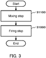
- FIG. 3 is a flowchart showing an example of the manufacturing method according to the third embodiment.
- the manufacturing method according to the third embodiment may further include a mixing step S1100.
- the mixing step S1100 is performed before the firing step S1000.
- a halide including Li a halide including Li
- a halide including Y a halide including Sm
- a halide including DC which are raw materials of the solid electrolyte material
- the halide including Li, the halide including Y, the halide including Sm, and the halide including DC may be prepared at a desired molar ratio and mixed.
- a known mixing tool e.g., a mortar, a blender, or a ball mill
- respective powders of the raw materials may be prepared and mixed.
- the mixed material in the form of powder may be fired.
- the mixed material in the form of powder obtained in the mixing step S1100 may be molded into pellets by pressure.
- the mixed material in the form of pellet may be fired.
- ⁇ , ⁇ , ⁇ , and ⁇ are each independently at least one selected from the group consisting of F, Cl, Br, and I.
- the mixed material may be obtained by mixing not only Li ⁇ , Y ⁇ 3 , Sm ⁇ s, and DC ⁇ 2 but also a raw material different from Li ⁇ , Y ⁇ 3 , Sm ⁇ s, and DC ⁇ 2 (e.g., M e X f described above).
- a raw material including Li ⁇ as the main component, a raw material including Y ⁇ 3 as the main component, a raw material including Sm ⁇ s as the main component, and a raw material including DC ⁇ 2 as the main component may be mixed.
- the main component refers to a component whose content at the molar ratio is the highest.
- FIG. 4 is a flowchart showing an example of the manufacturing method according to the third embodiment.
- the manufacturing method according to the third embodiment may further include a preparation step S1200.
- the preparation step S1200 is performed before the mixing step S1100.
- a halide including Li a halide including Li
- a halide including Y a halide including Sm
- a halide including DC i.e., materials to be mixed in the mixing step S1100
- Li ⁇ , Y ⁇ 3 , Sm ⁇ s, and DC ⁇ 2 are prepared.
- ⁇ , ⁇ , ⁇ , and ⁇ are each independently at least one selected from the group consisting of F, Cl, Br, and I.
- materials such as Li ⁇ , Y ⁇ 3 , Sm ⁇ s, and DC ⁇ 2 may be synthesized.
- a known commercially available product e.g., a material with a purity of 99% or more may be used.
- the materials to be prepared may be dry.
- the shape of the materials to be prepared is, for example, crystalline, massive, flake-like, or powdery.
- a crystalline, massive, or flake-like raw material may be pulverized to obtain the raw material in the form of powder.
- one or more of M e X f described above may be added. Owing to this, a solid electrolyte material thus manufactured can have improved characteristics (e.g., ionic conductivity).
- cations i.e., Li, Y, Sm, and DC
- another cation e.g., M described above.
- These raw material powders were pulverized and mixed in an agate mortar.
- the obtained mixed powder was put into an alumina crucible and fired in a dry argon atmosphere at 500°C for 60 minutes.
- a fired product thus obtained was pulverized in an agate mortar.
- a powder of a solid electrolyte material according to Example 1 was obtained.
- the solid electrolyte material according to Example 1 had a composition represented by Li 2 . 8 Ca 0.1 Y 0.8 Sm 0.2 Br 2 Cl 4 .
- FIG. 5 shows a schematic view of a pressure-molding die 300 used to evaluate the ionic conductivity of solid electrolyte materials.
- the pressure-molding die 300 included an upper punch 301, a die 302, and a lower punch 303.
- the upper punch 301 and the lower punch 303 were formed of electronically conductive stainless steel.
- the die 302 was formed of insulating polycarbonate.
- the pressure-molding die 300 shown in FIG. 5 was used to evaluate the ionic conductivity of the solid electrolyte material according to Example 1 by the following method.
- the powder of the solid electrolyte material according to Example 1 was charged into the pressure-molding die 300. Inside the pressure-molding die 300, a pressure of 360 MPa was applied to the solid electrolyte material according to Example 1 with the upper punch 301 and the lower punch 303.
- the upper punch 301 and the lower punch 303 were connected to a potentiostat (VersaSTAT4 available from Princeton Applied Research) equipped with a frequency response analyzer.
- the upper punch 301 was connected to a working electrode and a potential measurement terminal.
- the lower punch 303 was connected to a counter electrode and a reference electrode.
- the impedance of the solid electrolyte material was measured at room temperature by an electrochemical impedance measurement method.
- FIG. 6 is a graph showing a Cole-Cole plot obtained by impedance measurement for the solid electrolyte material according to Example 1.
- the real part of the complex impedance at the measurement point where the absolute value of the phase of the complex impedance was smallest was assumed to be the resistance value of the solid electrolyte material to ion conduction.
- R SE shown in FIG. 6 .
- the symbol S represents the contact area of the solid electrolyte material with the upper punch 301. In other words, the contact area S is equal to the cross-sectional area of the cavity of the die 302 in FIG. 5 .
- the symbol R SE represents the resistance value of the solid electrolyte material in the impedance measurement.
- the symbol t represents the thickness of the solid electrolyte material. In other words, the thickness t is equal to the thickness of a layer formed of the solid electrolyte material powder 101 in FIG. 5 .
- the ionic conductivity of the solid electrolyte material according to Example 1 measured at 24°C was 2.86 ⁇ 10 -3 S/cm.
- FIG. 7 is a graph showing an X-ray diffraction pattern of the solid electrolyte material according to Example 1. The results shown in FIG. 7 were measured by the following method.
- the X-ray diffraction pattern of the solid electrolyte material according to Example 1 was measured with an X-ray diffractometer (MiniFlex 600 available from Rigaku Corporation).
- the ⁇ -2 ⁇ method was used to measure the X-ray diffraction pattern with Cu-K ⁇ rays (wavelengths of 1.5405 ⁇ and 1.5444 ⁇ ) as X rays sources.
- the solid electrolyte material according to Example 1 and LiCoO 2 were prepared at a volume ratio of 30: 70. These materials were mixed in a mortar. Thus, a mixture was obtained.
- the solid electrolyte material according to Example 1 (80 mg) and the above mixture (10 mg) were stacked in this order.
- a pressure of 720 MPa was applied to form a solid electrolyte layer formed of the solid electrolyte material according to Example 1 and a first electrode formed of the above mixture.
- the solid electrolyte layer had a thickness of 600 ⁇ m.
- metal In (thickness of 200 ⁇ m), metal Li (thickness of 200 ⁇ m), and metal In (thickness of 200 ⁇ m) were stacked in order on the solid electrolyte layer.
- a pressure of 80 MPa was applied to form a second electrode.
- FIG. 9 is a graph showing the initial discharge characteristics of the battery according to Example 1. The initial charge and discharge characteristics were measured by the following method.
- the battery according to Example 1 was placed in a thermostatic chamber at 25°C.
- the battery according to Example 1 was charged to a voltage of 3.68 V at a current density of 78 ⁇ A/cm 2 .
- the current density corresponds to 0.05 C rate.
- Example 1 the battery according to Example 1 was discharged to a voltage of 1.88 V at a current density of 78 ⁇ A/cm 2 .
- the battery according to Example 1 had an initial discharge capacity of 1.2 mAh.
- the firing time was 180 minutes.
- the firing time was 180 minutes.
- the firing time was 180 minutes.
- Solid electrolyte materials according to Examples 2 to 25 were obtained in the same manner as in Example 1 except for the matters described above.
- Example 26 to 46 solid electrolyte materials according to Examples 26 to 46 were obtained in the same manner as in Example 1 except for the firing time and the firing temperature.
- the firing temperature and the firing time are shown in Table 1-2.
- the ionic conductivity was measured for the solid electrolyte materials according to Examples 2 to 46 in the same manner as in Example 1. The measurement results are shown in Tables 1-1 and 1-2.
- FIG. 7 is a graph showing the X-ray diffraction patterns of the solid electrolyte materials according to Examples 1 to 6, 10 to 12, 14, and 16 to 19. The angles of the observed diffraction peaks are shown in Table 2-1. All of the solid electrolyte materials shown in FIG. 7 had the first crystalline phase.
- FIG. 8 is a graph showing the X-ray diffraction patterns of the solid electrolyte materials according to Examples 7 to 9, 13, and 15. The angles of the observed diffraction peaks are shown in Table 2-2. All of the solid electrolyte materials shown in FIG. 8 had the second crystalline phase. Examples 8, 9, and 15 had not only the second crystalline phase but also the first crystalline phase.
- Batteries according to Examples 2 to 46 were obtained in the same manner as in Example 1 by using the solid electrolyte materials according to Examples 2 to 46. A charge and discharge test was performed in the same manner as in Example 1 by using the batteries according to Examples 2 to 46. As a result, the batteries according to Examples 2 to 46 were favorably charged and discharged as well as the battery according to Example 1.
- a solid electrolyte material according to Comparative Example 1 was obtained in the same manner as in Example 1 except for this.
- a solid electrolyte material according to Comparative Example 2 was obtained in the same manner as in Example 1 except for this.
- the ionic conductivity was measured for the solid electrolyte materials according to Comparative Examples 1 and 2 in the same manner as in Example 1. The measurement results are shown in Table 1-2.
- FIG. 7 and FIG. 8 are graphs showing the X-ray diffraction patterns of the solid electrolyte materials according to Comparative Examples 1 and 2. The angles of the observed diffraction peaks are shown in Tables 2-1 and 2-2. [Table 1-1] Composition a b c d DC Firing temp.
- Example 1 Li 2.8 Ca 0.1 Y 0.8 Sm 0.2 Br 2 Cl 4 0.1 0.2 4 0 Ca 500 60 2.86 ⁇ 10 -3
- Example 2 Li 2.8 Ca 0.1 Y 0.9 Sm 0.1 Br 2 Cl 4 0.1 0.1 4 0 Ca 500 60 2.88 ⁇ 10 -3
- Example 3 Li 2.8 Ca 0.1 Y 0.7 Sm 0.3 Br 2 Cl 4 0.1 0.3 4 0 Ca 500 60 2.78 ⁇ 10 -3
- Example 4 Li 2.8 Ca 0.1 Y 0.5 Sm 0.5 Br 2 Cl 4 0.1 0.5 4 0 Ca 500 60 2.49 ⁇ 10 -3
- Example 5 Li 2.8 Ca 0.1 Y 0.3 Sm 0.7 Br 2 Cl 4 0.1 0.7 4 0 Ca 500 60 6.56 ⁇ 10 -4
- Example 6 Li 2.8 Ca 0.1 Y 0.1 Sm 0.9 Br 2 Cl 4 0.1 0.9 4 0 Ca 500 60 1.81 ⁇ 10 -5
- Example 7 Li 2.8 Ca 0.1 Y 0.8 Sm 0.2 Br 6
- Example 26 Li 2.8 Ca 0.1 Y 0.8 Sm 0.2 Br 2 Cl 4 0.1 0.2 4 0 Ca 650 60 1.93 ⁇ 10 -3
- Example 27 Li 2.8 Ca 0.1 Y 0.8 Sm 0.2 Br 2 Cl 4 0.1 0.2 4 0 Ca 600 60 1.90 ⁇ 10 -3
- Example 28 Li 2.8 Ca 0.1 Y 0.8 Sm 0.2 Br 2 Cl 4 0.1 0.2 4 0 Ca 550 60 2.52 ⁇ 10 -3
- Example 29 Li 2.8 Ca 0.1 Y 0.8 Sm 0.2 Br 2 Cl 4 0.1 0.2 4 0 Ca 500 1 2.58 ⁇ 10 -3
- Example 30 Li 2.8 Ca 0.1 Y 0.8 Sm 0.2 Br 2 Cl 4 0.1 0.2 4 0 Ca 500 30 2.58 ⁇ 10 -3
- Example 31 Li 2.8 Ca 0.1 Y 0.8 Sm 0.2 Br 2 Cl 4 0.1 0.2 4 0 Ca 500 120 2.01 ⁇ 10 -3
- Example 32 Li 2.8 Ca 0.1 Y 0.8 Sm 0.2 Br
- the solid electrolyte materials according to Examples 1 to 46 have higher ionic conductivity of 1 ⁇ 10 -5 S/cm or more near room temperature.
- a solid electrolyte material having the value a being 0.1 or more and 0.25 or less has high ionic conductivity.
- a solid electrolyte material having the value a being 0.1 or more and 0.15 or less has higher ionic conductivity.
- a solid electrolyte material having the value b being 0.1 or more and 0.9 or less has high ionic conductivity.
- a solid electrolyte material having the value b being 0.1 or more and 0.5 or less has higher ionic conductivity.
- a solid electrolyte material including DC being at least one selected from the group consisting of Ca, Mg, and Sr has high ionic conductivity.
- a solid electrolyte material including DC being Ca has higher ionic conductivity.
- a solid electrolyte material having the value d being 0 or more and 0.05 or less has high ionic conductivity.
- a solid electrolyte material having the firing temperature being 450°C or more and 650°C or less has higher ionic conductivity. It is assumed that this is because the solid electrolyte material has higher crystallinity.
- a solid electrolyte material having the firing temperature being 450°C or more and 550°C or less has higher ionic conductivity. It is assumed that this is because the occurrence of thermal decomposition at a high temperature, that is, the occurrence of composition deviation of the solid electrolyte material can be suppressed.
- a solid electrolyte material having the firing time being 1 minute or more and 180 minutes or less has higher ionic conductivity. It is assumed that this is because thermal decomposition (i.e., composition deviation of the solid electrolyte material) caused by long-time firing can be suppressed.
- the solid electrolyte materials according to Examples 1 to 46 are free of sulfur, and accordingly generate no hydrogen sulfide.
- the solid electrolyte material according to the present disclosure has high lithium-ion conductivity and is suitable for providing a battery that can be charged and discharged favorably. Furthermore, the method of manufacturing the solid electrolyte material according to the present disclosure is an industrially productive method in which a solid electrolyte material having high ionic conductivity can be manufactured simply.
- the solid electrolyte material of the present disclosure and the method of manufacturing the same are utilized in, for example, batteries (e.g., all-solid-state lithium-ion secondary batteries).
Landscapes
- Chemical & Material Sciences (AREA)
- Engineering & Computer Science (AREA)
- General Chemical & Material Sciences (AREA)
- Electrochemistry (AREA)
- Chemical Kinetics & Catalysis (AREA)
- Manufacturing & Machinery (AREA)
- Organic Chemistry (AREA)
- Inorganic Chemistry (AREA)
- Condensed Matter Physics & Semiconductors (AREA)
- Geology (AREA)
- General Physics & Mathematics (AREA)
- Physics & Mathematics (AREA)
- Life Sciences & Earth Sciences (AREA)
- Materials Engineering (AREA)
- Secondary Cells (AREA)
- Conductive Materials (AREA)
Applications Claiming Priority (2)
| Application Number | Priority Date | Filing Date | Title |
|---|---|---|---|
| JP2020064805 | 2020-03-31 | ||
| PCT/JP2021/004428 WO2021199677A1 (ja) | 2020-03-31 | 2021-02-05 | 固体電解質材料、それを用いた電池、および固体電解質材料の製造方法 |
Publications (2)
| Publication Number | Publication Date |
|---|---|
| EP4131502A1 true EP4131502A1 (de) | 2023-02-08 |
| EP4131502A4 EP4131502A4 (de) | 2023-09-20 |
Family
ID=77927838
Family Applications (1)
| Application Number | Title | Priority Date | Filing Date |
|---|---|---|---|
| EP21779961.8A Withdrawn EP4131502A4 (de) | 2020-03-31 | 2021-02-05 | Festelektrolytmaterial, batterie damit und verfahren zur herstellung eines festelektrolytmaterials |
Country Status (5)
| Country | Link |
|---|---|
| US (1) | US12676338B2 (de) |
| EP (1) | EP4131502A4 (de) |
| JP (1) | JP7664539B2 (de) |
| CN (1) | CN115298754A (de) |
| WO (1) | WO2021199677A1 (de) |
Cited By (3)
| Publication number | Priority date | Publication date | Assignee | Title |
|---|---|---|---|---|
| EP4131506A4 (de) * | 2020-03-31 | 2023-09-27 | Panasonic Intellectual Property Management Co., Ltd. | Festelektrolytmaterial und batterie damit |
| EP4131500A4 (de) * | 2020-03-31 | 2023-09-27 | Panasonic Intellectual Property Management Co., Ltd. | Festelektrolytmaterial und batterie damit |
| EP4186862A4 (de) * | 2020-07-22 | 2024-02-21 | Panasonic Intellectual Property Management Co., Ltd. | Festelektrolytmaterial und batterie damit |
Families Citing this family (3)
| Publication number | Priority date | Publication date | Assignee | Title |
|---|---|---|---|---|
| EP4325615A4 (de) * | 2021-04-13 | 2025-08-06 | Panasonic Ip Man Co Ltd | Batterie |
| KR20240105923A (ko) * | 2022-12-29 | 2024-07-08 | 현대자동차주식회사 | 새로운 결정구조를 갖는 전고체 전지용 리튬 메탈 할라이드계 고체전해질 |
| CN122000439A (zh) * | 2025-09-08 | 2026-05-08 | 浙江绿色智行科创有限公司 | 卤化物电解质的制备方法以及固态电池 |
Family Cites Families (7)
| Publication number | Priority date | Publication date | Assignee | Title |
|---|---|---|---|---|
| KR100612570B1 (ko) * | 2004-04-21 | 2006-08-11 | 주식회사 엘지화학 | 신규 결정 구조를 갖는 금속 복합 산화물 및 이들의 이온전도체로서의 용도 |
| CN100590173C (zh) * | 2006-03-24 | 2010-02-17 | 北京有色金属研究总院 | 一种荧光粉及其制造方法和所制成的电光源 |
| JP5141675B2 (ja) | 2009-12-16 | 2013-02-13 | トヨタ自動車株式会社 | 硫化物固体電解質材料の製造方法、硫化物固体電解質材料およびリチウム電池 |
| US10522873B2 (en) * | 2015-12-15 | 2019-12-31 | Sila Nanotechnologies Inc. | Solid state electrolytes for safe metal and metal-ion batteries |
| CN114937812B (zh) | 2016-08-04 | 2025-02-28 | 松下知识产权经营株式会社 | 固体电解质材料和电池 |
| US10930927B2 (en) * | 2017-11-08 | 2021-02-23 | Samsung Electronics Co., Ltd. | Positive electrode active material, methods for the manufacture thereof, and electrochemical cell comprising the positive electrode active material |
| EP3736834A4 (de) | 2018-01-05 | 2021-03-10 | Panasonic Intellectual Property Management Co., Ltd. | Festelektrolytmaterial und batterie |
-
2021
- 2021-02-05 WO PCT/JP2021/004428 patent/WO2021199677A1/ja not_active Ceased
- 2021-02-05 JP JP2022511604A patent/JP7664539B2/ja active Active
- 2021-02-05 CN CN202180021695.XA patent/CN115298754A/zh active Pending
- 2021-02-05 EP EP21779961.8A patent/EP4131502A4/de not_active Withdrawn
-
2022
- 2022-09-29 US US17/956,379 patent/US12676338B2/en active Active
Cited By (5)
| Publication number | Priority date | Publication date | Assignee | Title |
|---|---|---|---|---|
| EP4131506A4 (de) * | 2020-03-31 | 2023-09-27 | Panasonic Intellectual Property Management Co., Ltd. | Festelektrolytmaterial und batterie damit |
| EP4131500A4 (de) * | 2020-03-31 | 2023-09-27 | Panasonic Intellectual Property Management Co., Ltd. | Festelektrolytmaterial und batterie damit |
| US12463247B2 (en) | 2020-03-31 | 2025-11-04 | Panasonic Intellectual Property Management Co., Ltd. | Solid electrolyte material and battery using same |
| EP4186862A4 (de) * | 2020-07-22 | 2024-02-21 | Panasonic Intellectual Property Management Co., Ltd. | Festelektrolytmaterial und batterie damit |
| US12676339B2 (en) | 2020-07-22 | 2026-07-07 | Panasonic Intellectual Property Management Co., Ltd. | Solid electrolyte material and battery using same |
Also Published As
| Publication number | Publication date |
|---|---|
| JPWO2021199677A1 (de) | 2021-10-07 |
| EP4131502A4 (de) | 2023-09-20 |
| US20230040104A1 (en) | 2023-02-09 |
| US12676338B2 (en) | 2026-07-07 |
| JP7664539B2 (ja) | 2025-04-18 |
| CN115298754A (zh) | 2022-11-04 |
| WO2021199677A1 (ja) | 2021-10-07 |
Similar Documents
| Publication | Publication Date | Title |
|---|---|---|
| EP3863026B1 (de) | Halid-feststoffelektrolytmaterial und batterie damit | |
| EP3863025B1 (de) | Halid-festelektrolytmaterial und batterie damit | |
| EP4044291A1 (de) | Feststoffelektrolytmaterial und batterie mit verwendung davon | |
| EP3863027B1 (de) | Halid-festelektrolytmaterial und batterie damit | |
| US20230040104A1 (en) | Solid electrolyte material, battery using same, and method for producing solid electrolyte material | |
| EP4123746A1 (de) | Festelektrolytmaterial und zelle damit | |
| EP3951973A1 (de) | Feststoffelektrolytmaterial und batterie mit verwendung davon | |
| EP3736832B1 (de) | Festelektrolytmaterial und batterie | |
| EP4106044A1 (de) | Feststoffelektrolytmaterial und batterie mit verwendung davon | |
| CN114976223A (zh) | 固体电解质材料和电池 | |
| EP3736823A1 (de) | Festelektrolytmaterial und batterie | |
| EP4238937A1 (de) | Festelektrolytmaterial und batterie damit | |
| EP4123745A1 (de) | Festelektrolytmaterial und batterie damit | |
| EP4186864A1 (de) | Festelektrolytmaterial und batterie damit | |
| US20230021952A1 (en) | Solid electrolyte material and battery using same | |
| EP3940814B1 (de) | Feststoffelektrolytmaterial und batterie mit verwendung davon | |
| EP4144699A1 (de) | Festelektrolytmaterial und batterie damit | |
| EP4163990A1 (de) | Festelektrolytmaterial und batterie damit | |
| EP4238938A1 (de) | Festelektrolytmaterial und batterie damit | |
| US20230155170A1 (en) | Solid electrolyte material and battery using same | |
| EP4538235A1 (de) | Vanadiumoxid und batterie damit | |
| EP4322242B1 (de) | Festelektrolytmaterial und batterie damit | |
| EP4186863B1 (de) | Festelektrolytmaterial und batterie damit | |
| EP4144700A1 (de) | Festelektrolytmaterial und batterie damit | |
| EP4131506A1 (de) | Festelektrolytmaterial und batterie damit |
Legal Events
| Date | Code | Title | Description |
|---|---|---|---|
| STAA | Information on the status of an ep patent application or granted ep patent |
Free format text: STATUS: THE INTERNATIONAL PUBLICATION HAS BEEN MADE |
|
| PUAI | Public reference made under article 153(3) epc to a published international application that has entered the european phase |
Free format text: ORIGINAL CODE: 0009012 |
|
| STAA | Information on the status of an ep patent application or granted ep patent |
Free format text: STATUS: REQUEST FOR EXAMINATION WAS MADE |
|
| 17P | Request for examination filed |
Effective date: 20220928 |
|
| AK | Designated contracting states |
Kind code of ref document: A1 Designated state(s): AL AT BE BG CH CY CZ DE DK EE ES FI FR GB GR HR HU IE IS IT LI LT LU LV MC MK MT NL NO PL PT RO RS SE SI SK SM TR |
|
| DAV | Request for validation of the european patent (deleted) | ||
| DAX | Request for extension of the european patent (deleted) | ||
| A4 | Supplementary search report drawn up and despatched |
Effective date: 20230822 |
|
| RIC1 | Information provided on ipc code assigned before grant |
Ipc: H01M 6/18 20060101ALI20230816BHEP Ipc: C01F 17/36 20200101ALI20230816BHEP Ipc: H01B 1/06 20060101ALI20230816BHEP Ipc: H01M 10/0562 20100101ALI20230816BHEP Ipc: H01M 4/62 20060101AFI20230816BHEP |
|
| STAA | Information on the status of an ep patent application or granted ep patent |
Free format text: STATUS: THE APPLICATION HAS BEEN WITHDRAWN |
|
| 18W | Application withdrawn |
Effective date: 20251017 |