EP4131557A1 - Appareil électrochimique et appareil électronique utilisant un appareil électrochimique - Google Patents
Appareil électrochimique et appareil électronique utilisant un appareil électrochimique Download PDFInfo
- Publication number
- EP4131557A1 EP4131557A1 EP20928190.6A EP20928190A EP4131557A1 EP 4131557 A1 EP4131557 A1 EP 4131557A1 EP 20928190 A EP20928190 A EP 20928190A EP 4131557 A1 EP4131557 A1 EP 4131557A1
- Authority
- EP
- European Patent Office
- Prior art keywords
- adhesive member
- separator
- electrochemical apparatus
- current collector
- straight section
- Prior art date
- Legal status (The legal status is an assumption and is not a legal conclusion. Google has not performed a legal analysis and makes no representation as to the accuracy of the status listed.)
- Pending
Links
Images


Classifications
-
- H—ELECTRICITY
- H01—ELECTRIC ELEMENTS
- H01M—PROCESSES OR MEANS, e.g. BATTERIES, FOR THE DIRECT CONVERSION OF CHEMICAL ENERGY INTO ELECTRICAL ENERGY
- H01M10/00—Secondary cells; Manufacture thereof
- H01M10/05—Accumulators with non-aqueous electrolyte
- H01M10/058—Construction or manufacture
- H01M10/0587—Construction or manufacture of accumulators having only wound construction elements, i.e. wound positive electrodes, wound negative electrodes and wound separators
-
- H—ELECTRICITY
- H01—ELECTRIC ELEMENTS
- H01M—PROCESSES OR MEANS, e.g. BATTERIES, FOR THE DIRECT CONVERSION OF CHEMICAL ENERGY INTO ELECTRICAL ENERGY
- H01M10/00—Secondary cells; Manufacture thereof
- H01M10/04—Construction or manufacture in general
- H01M10/0431—Cells with wound or folded electrodes
-
- H—ELECTRICITY
- H01—ELECTRIC ELEMENTS
- H01M—PROCESSES OR MEANS, e.g. BATTERIES, FOR THE DIRECT CONVERSION OF CHEMICAL ENERGY INTO ELECTRICAL ENERGY
- H01M10/00—Secondary cells; Manufacture thereof
- H01M10/04—Construction or manufacture in general
-
- H—ELECTRICITY
- H01—ELECTRIC ELEMENTS
- H01M—PROCESSES OR MEANS, e.g. BATTERIES, FOR THE DIRECT CONVERSION OF CHEMICAL ENERGY INTO ELECTRICAL ENERGY
- H01M10/00—Secondary cells; Manufacture thereof
- H01M10/05—Accumulators with non-aqueous electrolyte
- H01M10/052—Li-accumulators
-
- H—ELECTRICITY
- H01—ELECTRIC ELEMENTS
- H01M—PROCESSES OR MEANS, e.g. BATTERIES, FOR THE DIRECT CONVERSION OF CHEMICAL ENERGY INTO ELECTRICAL ENERGY
- H01M10/00—Secondary cells; Manufacture thereof
- H01M10/05—Accumulators with non-aqueous electrolyte
- H01M10/052—Li-accumulators
- H01M10/0525—Rocking-chair batteries, i.e. batteries with lithium insertion or intercalation in both electrodes; Lithium-ion batteries
-
- H—ELECTRICITY
- H01—ELECTRIC ELEMENTS
- H01M—PROCESSES OR MEANS, e.g. BATTERIES, FOR THE DIRECT CONVERSION OF CHEMICAL ENERGY INTO ELECTRICAL ENERGY
- H01M50/00—Constructional details or processes of manufacture of the non-active parts of electrochemical cells other than fuel cells, e.g. hybrid cells
- H01M50/40—Separators; Membranes; Diaphragms; Spacing elements inside cells
- H01M50/409—Separators, membranes or diaphragms characterised by the material
- H01M50/411—Organic material
- H01M50/414—Synthetic resins, e.g. thermoplastics or thermosetting resins
- H01M50/417—Polyolefins
-
- H—ELECTRICITY
- H01—ELECTRIC ELEMENTS
- H01M—PROCESSES OR MEANS, e.g. BATTERIES, FOR THE DIRECT CONVERSION OF CHEMICAL ENERGY INTO ELECTRICAL ENERGY
- H01M50/00—Constructional details or processes of manufacture of the non-active parts of electrochemical cells other than fuel cells, e.g. hybrid cells
- H01M50/40—Separators; Membranes; Diaphragms; Spacing elements inside cells
- H01M50/46—Separators, membranes or diaphragms characterised by their combination with electrodes
- H01M50/461—Separators, membranes or diaphragms characterised by their combination with electrodes with adhesive layers between electrodes and separators
-
- H—ELECTRICITY
- H01—ELECTRIC ELEMENTS
- H01M—PROCESSES OR MEANS, e.g. BATTERIES, FOR THE DIRECT CONVERSION OF CHEMICAL ENERGY INTO ELECTRICAL ENERGY
- H01M50/00—Constructional details or processes of manufacture of the non-active parts of electrochemical cells other than fuel cells, e.g. hybrid cells
- H01M50/50—Current conducting connections for cells or batteries
- H01M50/531—Electrode connections inside a battery casing
- H01M50/538—Connection of several leads or tabs of wound or folded electrode stacks
-
- H—ELECTRICITY
- H01—ELECTRIC ELEMENTS
- H01M—PROCESSES OR MEANS, e.g. BATTERIES, FOR THE DIRECT CONVERSION OF CHEMICAL ENERGY INTO ELECTRICAL ENERGY
- H01M10/00—Secondary cells; Manufacture thereof
- H01M10/42—Methods or arrangements for servicing or maintenance of secondary cells or secondary half-cells
- H01M10/4235—Safety or regulating additives or arrangements in electrodes, separators or electrolyte
-
- H—ELECTRICITY
- H01—ELECTRIC ELEMENTS
- H01M—PROCESSES OR MEANS, e.g. BATTERIES, FOR THE DIRECT CONVERSION OF CHEMICAL ENERGY INTO ELECTRICAL ENERGY
- H01M50/00—Constructional details or processes of manufacture of the non-active parts of electrochemical cells other than fuel cells, e.g. hybrid cells
- H01M50/20—Mountings; Secondary casings or frames; Racks, modules or packs; Suspension devices; Shock absorbers; Transport or carrying devices; Holders
- H01M50/233—Mountings; Secondary casings or frames; Racks, modules or packs; Suspension devices; Shock absorbers; Transport or carrying devices; Holders characterised by physical properties of casings or racks, e.g. dimensions
- H01M50/242—Mountings; Secondary casings or frames; Racks, modules or packs; Suspension devices; Shock absorbers; Transport or carrying devices; Holders characterised by physical properties of casings or racks, e.g. dimensions adapted for protecting batteries against vibrations, collision impact or swelling
-
- Y—GENERAL TAGGING OF NEW TECHNOLOGICAL DEVELOPMENTS; GENERAL TAGGING OF CROSS-SECTIONAL TECHNOLOGIES SPANNING OVER SEVERAL SECTIONS OF THE IPC; TECHNICAL SUBJECTS COVERED BY FORMER USPC CROSS-REFERENCE ART COLLECTIONS [XRACs] AND DIGESTS
- Y02—TECHNOLOGIES OR APPLICATIONS FOR MITIGATION OR ADAPTATION AGAINST CLIMATE CHANGE
- Y02E—REDUCTION OF GREENHOUSE GAS [GHG] EMISSIONS, RELATED TO ENERGY GENERATION, TRANSMISSION OR DISTRIBUTION
- Y02E60/00—Enabling technologies; Technologies with a potential or indirect contribution to GHG emissions mitigation
- Y02E60/10—Energy storage using batteries
-
- Y—GENERAL TAGGING OF NEW TECHNOLOGICAL DEVELOPMENTS; GENERAL TAGGING OF CROSS-SECTIONAL TECHNOLOGIES SPANNING OVER SEVERAL SECTIONS OF THE IPC; TECHNICAL SUBJECTS COVERED BY FORMER USPC CROSS-REFERENCE ART COLLECTIONS [XRACs] AND DIGESTS
- Y02—TECHNOLOGIES OR APPLICATIONS FOR MITIGATION OR ADAPTATION AGAINST CLIMATE CHANGE
- Y02P—CLIMATE CHANGE MITIGATION TECHNOLOGIES IN THE PRODUCTION OR PROCESSING OF GOODS
- Y02P70/00—Climate change mitigation technologies in the production process for final industrial or consumer products
- Y02P70/50—Manufacturing or production processes characterised by the final manufactured product
Definitions
- This application relates to the field of energy storage technologies, and in particular, to an electrochemical apparatus and an electronic apparatus using such electrochemical apparatus.
- Electrochemical apparatuses are widely applied in fields such as consumer electronics, electric devices, electric vehicles, and electric tools as technologies for processing electrochemical apparatuses mature.
- separators are used to terminate electrode assemblies in the process of manufacturing to improve the safety performance of the electrochemical apparatuses.
- electrochemical apparatuses are prone to failure because separators are easily damaged in the case of mechanical abuse (for example, falling, impact, and collision), resulting in increased safety risks and reduced service life of the electrochemical apparatuses.
- the electrode assembly includes electrode plates and a separator, the electrode plates and the separator are stacked sequentially and wound to form the electrode assembly, the electrode plate includes a current collector, and the electrode assembly includes a first straight section and a first bending section that are connected to each other.
- a terminating end of the separator exceeds a terminating end of the current collector by 1 to 5 turns
- the first adhesive member is disposed on an outer surface of the first straight section
- the second adhesive member is disposed on an outer surface of the first bending section or an outer surface of the outermost current collector at the first bending section.
- the terminating end of the separator is wound for 1 to 5 turns to form a protective layer, which effectively increases mechanical impact resistance of the outer separator.
- the second adhesive member is disposed on the outer surface of the first bending section or the outer surface of the outermost current collector at the first bending section, preventing the terminating separator at the first bending section from being damaged.
- the first adhesive member is disposed on the outer surface of the first straight section, which can enhance strength of the terminating separator at the first straight section along a direction perpendicular to the winding direction. In this way, safety and service life of electrochemical apparatuses are improved.
- the second adhesive member is disposed on the outer surface of the first bending section and includes a first extension portion, and the first extension portion is disposed on the outer surface of the first straight section.
- the first extension portion being disposed on the first straight section can protect the terminating separator at the connecting corner of the first straight section and the first bending section, alleviating the problem that the electrochemical apparatus fails because the terminating separator at the corner is easily damaged in the case of mechanical abuse, and improving the safety, reliability, and service life of the electrochemical apparatus.
- the second adhesive member is disposed on the outer surface of the outermost current collector at the first bending section
- the first extension portion is disposed on the outer surface of the outermost current collector at the first straight section.
- the first extension portion being disposed on the outer surface of the outermost current collector at the first straight section can relieve mutual pressing between the current collector and the terminating separator at the connecting corner of the first straight section and the first bending section, alleviating the problem that the electrochemical apparatus fails because the terminating separator at the corner is easily damaged in the case of mechanical abuse, and improving the safety, reliability, and service life of the electrochemical apparatus.
- a width W 1 of the first extension portion satisfies 0 mm ⁇ W 1 ⁇ 5 mm.
- the electrode assembly further includes a second straight section, where the second straight section is connected to the first bending section; and the second adhesive member further includes a second extension portion, where the second extension portion is disposed on an outer surface of the second straight section.
- the provision of the second extension portion can further protect the terminating separator at the corner, alleviating the problem that the electrochemical apparatus fails because the terminating separator at the junction of the first being section and the second straight section is easily damaged in the case of mechanical abuse, and further improving the safety, reliability, and service life of the electrochemical apparatus.
- the second extension portion is disposed on an outer surface of the outermost current collector at the second straight section.
- the second extension portion being disposed on the outer surface of the outermost current collector at the second straight section can further relieve the mutual pressing between the current collector and the terminating separator at the junction of the first bending section and the second straight section, alleviating the problem that the electrochemical apparatus fails because the terminating separator at the corner is easily damaged in the case of mechanical abuse, and further improving the safety, reliability, and service life of the electrochemical apparatus.
- the electrochemical apparatus further includes a third adhesive member
- the electrode assembly further includes a second bending section, where two ends of the second bending section are respectively connected to a first straight section and a second straight section, and the third adhesive member is disposed on an outer surface of the second bending section or an outer surface of the outermost current collector at the second bending section.
- the provision of the third adhesive member on the outer surface of the second bending section or the outer surface of the outermost current collector at the second bending section can prevent the terminating separator at the second bending section from being damaged, further improving the safety and service life of the electrochemical apparatus.
- a width W 2 of the first adhesive member satisfies 5 mm ⁇ W 2 ⁇ 50 mm. If the width of the first adhesive member is too small, damage to the terminating separator along the winding direction in the case of mechanical abuse cannot be avoided; and if the width of the first adhesive member is too large, the thickness of the electrode assembly is affected, decreasing the energy density thereof.
- a width W 3 of the separator and a length L 2 of the first adhesive member satisfy 10 mm ⁇ W 3 -L 2 ⁇ 30 mm. If the length of the first adhesive member is too small, damage to the terminating separator in the case of mechanical abuse cannot be avoided in the direction perpendicular to the winding direction; and if the length of the first adhesive member is too large, the thickness of the electrode assembly is affected, decreasing the energy density thereof.
- the electrochemical apparatus further includes a fourth adhesive member, and the fourth adhesive member adheres to an outer surface of the outermost current collector at the first straight section and the separator opposite the outer surface of the outermost current collector at the first straight section.
- the outermost current collector at the first straight section and the corresponding terminating separator are bonded to form an integrated structure, which enhances strength of the terminating separator thereat, further alleviates the problem that the electrochemical apparatus fails in the case of mechanical abuse, improving the safety, reliability, and service life of the electrochemical apparatus.
- the terminating end of the separator exceeds the terminating end of the current collector by 1 turn.
- the terminating separator is wound for 1 turn so that the integrated structure formed by the outermost current collector at the first straight section and the terminating separator has high strength, which further improves the safety, reliability, and service life of the electrochemical apparatus.
- the fourth adhesive member covers a projection of the first adhesive member in a plane where the fourth adhesive member is located.
- the first adhesive member and the fourth adhesive member overlap, further enhancing strength of the integrated structure formed by the outermost current collector at the first straight section and the terminating separator, which further improves the safety, reliability, and service life of the electrochemical apparatus.
- a width W 4 of the fourth adhesive member and a width W 2 of the first adhesive member satisfy 4 mm ⁇ W 4 -W 2 ⁇ 10 mm.
- the fourth adhesive member exceeds, in terms of width, the first adhesive member by a specified range, enhancing strength of the integrated structure formed by the outermost current collector at the first straight section and the terminating separator along the winding direction, which further improves the safety, reliability, and service life of the electrochemical apparatus.
- a length L 4 of the fourth adhesive member and a length L 2 of the first adhesive member satisfy 4 mm ⁇ L 4 -L 2 ⁇ 10 mm.
- the fourth adhesive member exceeds, in terms of width, the first adhesive member by a specified range, enhancing strength of the integrated structure formed by the outermost current collector at the first straight section and the terminating separator in the direction perpendicular to the winding direction, which further improves the safety, reliability, and service life of the electrochemical apparatus.
- the electrochemical apparatus further includes a shell, where the electrode assembly is accommodated in the shell, and the first adhesive member is bonded to the shell.
- the first adhesive member being bonded to the shell can make the electrode assembly and the shell form an integrated structure, alleviating the problem that the electrochemical apparatus fails in the case of mechanical abuse, which further improves the safety, reliability, and service life of the electrochemical apparatus.
- the separator is a polypropylene separator.
- the use of a separator made of polypropylene can effectively reduce the cost of the electrochemical apparatus.
- This application further provides an electronic apparatus, including the foregoing electrochemical apparatus.
- Electrochemical apparatus 100 Electrode assembly 10 Electrode plate 11 Current collector 111 First electrode plate A Second electrode plate B Separator 12 First straight section 13 Outermost current collector at first straight section 131 First bending section 14 Outermost current collector at first bending section 141 Second straight section 15 Outermost current collector at second straight section 151 Second bending section 16 Outermost current collector at second bending section 161 First adhesive member 20 Second adhesive member 30 First extension portion 31 Second extension portion 32 Third adhesive member 40 Fourth adhesive member 50 Tab 60
- An electrochemical apparatus which includes an electrode assembly, a first adhesive member, and a second adhesive member.
- the electrode assembly includes electrode plates and a separator, the electrode plates and the separator are stacked sequentially and wound to form the electrode assembly, the electrode plate includes a current collector, and the electrode assembly further includes a first straight section and a first bending section that are connected to each other.
- a terminating end of the separator exceeds a terminating end of the current collector by 1 to 5 turns
- the first adhesive member is disposed on an outer surface of the first straight section
- the second adhesive member is disposed on an outer surface of the first bending section or an outer surface of the outermost current collector at the first bending section.
- the terminating end of the separator is wound for 1 to 5 turns to form a protective layer, which effectively increases mechanical impact resistance of an outer separator.
- the second adhesive member is disposed on an outer surface of the first bending section or an outer surface of the outermost current collector at the first bending section so as to prevent the terminating separator at the first bending section from being damaged.
- the first adhesive member is disposed on the outer surface of the first straight section, which can enhance strength of the terminating separator at the first straight section along a direction perpendicular to the winding direction, increasing the pass rate of electrochemical apparatuses in safety performance test, and improving the safety and service life of the electrochemical apparatuses.
- the terminating end of the separator being so provided as to exceed the terminating end of the current collector by 1 to 5 turns is out of consideration of the protection effect as well as consideration of the cost of materials and energy density loss of the electrochemical apparatus. If the separator is wound too much, the cost is increased correspondingly and the energy density is reduced.
- a winding direction is a direction that a point on the electrode assembly moves along the current collector or the separator from inside outward. There may be two winding directions: clockwise winding and counterclockwise winding.
- one turn means one circle of trip of the wound electrode assembly along the winding direction starting at one point and ending at another point, where the end point and the start point are located on a same side of the electrode assembly.
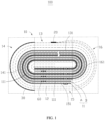
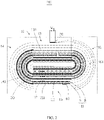
- an electrochemical apparatus 100 includes an electrode assembly 10, a first adhesive member 20, and a second adhesive member 30.
- the electrode assembly 10 includes electrode plates 11 and a separator 12, the electrode plates 11 and the separator 12 are stacked sequentially and wound to form the electrode assembly 10, the electrode plate 11 includes a current collector 111, and the electrode assembly 10 further includes a first straight section 13 and a first bending section 14 that are connected to each other.
- the first adhesive member 20 is disposed on an outer surface of the first straight section 13
- the second adhesive member 30 is disposed on an outer surface of the first bending section 14 or an outer surface of the outermost current collector 141 at the first bending section.
- the starting end is an end where the electrode plates 11 or the separator 12 starts to be wound along the winding direction; and the terminating end is an end where the electrode plates 11 or the separator 12 terminates the winding along the winding direction.
- the outer surface is a surface away from the winding starting end.
- the electrode plates 11 include a first electrode plate A and a second electrode plate B, where the separator 12 is disposed between the first electrode plate A and the second electrode plate B and wound.
- the first electrode plate A is an anode electrode plate
- the second electrode plate B is a cathode electrode plate.
- first electrode plate A and the second electrode plate B may be interchangeable, meaning that the first electrode plate A is a cathode electrode plate, and the second electrode plate B is an anode electrode plate.
- the outermost current collector 141 at the first bending section is an aluminum foil. In an embodiment, the outermost current collector 141 at the first bending section is a copper foil. It can be understood that, in other embodiments, materials of the outermost current collector 111 are not limited thereto.
- the starting end of the separator 12 and those of the electrode plates 11 are wound together. After winding of an electrode plate 11 is terminated, the outermost surface of the electrode plate 11 is typically an outer surface of the current collector 111.
- the terminating end of the separator 12 exceeding the terminating end of the current collector 111 by a plurality of turns can form a protective layer on the surface of the current collector 111, which effectively increases mechanical impact resistance of the outer separator, preventing the separator 12 from being damaged in the case of mechanical abuse and protecting the internal structure of the electrochemical apparatus 100 from damage under external mechanical impact force.
- the electrode assembly 10 further includes a second straight section 15 and a second bending section 16.
- the first straight section 13 and the second straight section 15 are disposed in vertical direction (the direction shown in the drawings is for reference), with the first straight section 13 located on the top and the second straight section 15 located at the bottom.
- the first bending section 14 and the second bending section 16 are disposed in horizontal direction (the direction shown in the drawings is for reference), with the first bending section 14 located on the left and the second bending section 16 located on the right.
- Two ends of the first bending section 14 are respectively connected to one end of the first straight section 13 and one end of the second straight section 15; and two ends of the second bending section 16 are respectively connected to the other end of the first straight section 13 and the other end of the second straight section 15.
- the first straight section 13, the first bending section 14, the second straight section 15, and the second bending section 16 are straight sections and bending sections that all include the electrode plates 11 and the separator 12, so that the straight sections and bending sections of the electrode plates 11 and separator 12 as a whole are divided into four zones: the first straight section 13, the first bending section 14, the second straight section 15, and the second bending section 16.
- the first straight section 13 includes the outermost current collector 131 at the first straight section, and the outermost current collector 131 at the first straight section is located on the outermost layer of the current collector 111 at the first straight section 13.
- the first bending section 14 includes the outermost current collector 141 at the first bending section, the outermost current collector 141 at the first bending section is located on the outermost layer of the current collector 111 at the first bending section 14, and one end of the outermost current collector 131 at the first straight section is connected to one end of the outermost current collector 141 at the first bending section.
- the second straight section 15 includes the outermost current collector 151 at the second straight section, the outermost current collector 151 at the second straight section is located on the outermost layer of the current collector 111 at the second straight section 15, and one end of the outermost current collector 151 at the second straight section is connected to the other end of the outermost current collector 141 at the first bending section.
- the second bending section 16 includes the outermost current collector 161 at the second bending section, the outermost current collector 161 at the second bending section is located on the outermost layer of the current collector 111 at the second bending section 16, and two ends of the outermost current collector 161 at the second bending section are respectively connected to one end of the outermost current collector 131 at the first straight section and one end of the outermost current collector 151 at the second straight section.
- the first adhesive member 20 is disposed on an outer surface of the first straight section 13, meaning that the first adhesive member 20 is disposed on an outer surface of the separator 12 at the first straight section 13. In other words, after the terminating end of the separator 12 is coated onto the current collector 111 by plural turns, the first adhesive member 20 is disposed on the outer surface of the terminating end. Further, the first adhesive member 20 is disposed at a middle position of the first straight section 13 along the winding direction.
- a width W 2 of the first adhesive member 20 satisfies 5 mm ⁇ W 2 ⁇ 50 mm. If the width of the first adhesive member 20 is too small, damage to the terminating separator 12 in the case of mechanical abuse cannot be avoided along the winding direction. If the width of the first adhesive member 20 is too large, thickness of the electrode assembly 10 is affected, decreasing the energy density thereof. Therefore, the width of the first adhesive member 20 is 5 mm ⁇ W 2 ⁇ 50 mm.
- a length of the first adhesive member 20 is L 2
- a width of the separator 12 is W 3 .
- the width W 3 of the separator 12 and the length L 2 of the first adhesive member 20 satisfy 10 mm ⁇ W 3 -L 2 ⁇ 30 mm. If the length of the first adhesive member 20 is too small, damage to the terminating separator 12 in the case of mechanical abuse cannot be avoided in the direction perpendicular to the winding direction; and if the length of the first adhesive member 20 is too large, the thickness of the electrode assembly is affected, decreasing the energy density thereof.
- the first adhesive member 20 may alternatively be disposed on an outer surface of the second straight section 15.
- the first adhesive member 20 is disposed on an outer surface of the separator 12 at the second straight section 15.
- the first adhesive member 20 is disposed on both the outer surface of the first straight section 13 and the outer surface of the second straight section 15.
- the second adhesive member 30 is disposed on the outer surface of the first bending section 14. Further, one end of the second adhesive member 30 includes a first extension portion 31, and the first extension portion 31 is disposed on the outer surface of the first straight section 13.
- the second adhesive member 30 is disposed on the outer surface of the first bending section 14, and the first extension portion 31 on the end thereof is disposed on the first straight section 13 connected to the first bending section 14, which can effectively protect a transition section between the first bending section 14 and the first straight section 13 and protect the terminating separator 12 at the junction of the first straight section 13 and the first bending section 14, alleviating the problem that the electrochemical apparatus 100 fails because the terminating separator 12 at the junction is easily damaged in the case of mechanical abuse, and improving the safety, reliability, and service life of the electrochemical apparatus.
- the width W 1 of the first extension portion 31 satisfies 0 mm ⁇ W 1 ⁇ 5 mm.
- the first extension portion 31 should be ensured to extend beyond the first bending section 14 to the first straight section 13. Such arrangement guarantees that the first extension portion 31 is wide enough to protect the terminating separator 12 at the corner from being damaged, without increasing the thickness of the first straight section 13 too much while such increase results in a decrease in energy density.
- the other end of the second adhesive member 30 further includes a second extension portion 32, and the second extension portion 32 is disposed on the outer surface of the second straight section 15.
- the structure and width of the second extension portion 32 are roughly the same as those of the first extension portion 31.
- the second extension portion 32 is disposed to further protect corners of the terminating separator 12, which alleviates the problem that the electrochemical apparatus 100 fails because the terminating separator 12 at the junction of the first bending section 14 and the second straight section 15 is easily damaged in the case of mechanical abuse, further improving the safety, reliability, and service life of the electrochemical apparatus.
- the electrochemical apparatus 100 further includes a third adhesive member 40, and the third adhesive member 40 is disposed on an outer surface of the second bending section 16.
- the third adhesive member 40 has the same shape and structure as the second adhesive member 30, and a difference between them only lies in that one is disposed on the first bending section 14 and the other is disposed on the second bending section 16.
- the adhesive members being respectively disposed on the first bending section 14 and second bending section 16 of the electrode assembly 10 can effectively protect the first straight section 13, the first bending section 14, and the second bending section 16.
- the terminating end of the separator 12 can be wound to the first bending section 14 or second bending section 16 of the electrode assembly 10, and is secured by the second adhesive member 30 or third adhesive member 40.
- the second adhesive member 30 is disposed on the outer surface of the outermost current collector 141 at the first bending section, and the first extension portion 31 of the second adhesive member 30 is disposed on an outer surface of the outermost current collector 131 at the first straight section.
- the second extension portion 32 of the second adhesive member 30 is disposed on an outer surface of the outermost current collector 151 at the second straight section.
- the first extension portion 31 is disposed on the outer surface of the outermost current collector 131 at the first straight section, which can relieve mutual pressing between the current collector 111 and the terminating separator 12 at the connecting corner of the first straight section 13 and the first bending section 14, alleviating the problem that the electrochemical apparatus fails because the terminating separator 12 at the connecting corner is easily damaged in the case of mechanical abuse, which improves the safety, reliability, and service life of the electrochemical apparatus.
- the second extension portion 32 is disposed on the outer surface of the outermost current collector 151 at the second straight section, which can also relieve the mutual pressing between the current collector 111 and the terminating separator 12 at the junction of the first bending section 14 and the second straight section 15, thereby avoiding failure of the electrochemical apparatus 100.
- the third adhesive member 40 may be also disposed on an outer surface of the outermost current collector 161 at the second bending section, so as to alleviate the problem that the terminating separator 12 at the second bending section is easily damaged.
- the electrochemical apparatus 100 further includes a fourth adhesive member 50 and the fourth adhesive member 50 adheres to an outer surface of the outermost current collector 131 at the first straight section and the separator 12 opposite the outer surface of the outermost current collector 131 at the first straight section.
- the outermost current collector 131 at the first straight section and the corresponding terminating separator 12 are bonded to form an integrated structure, which enhances strength of the terminating separator 12 thereat, further alleviating the problem that the electrochemical apparatus 100 fails in the case of mechanical abuse, and improving the safety, reliability, and service life of the electrochemical apparatus.
- the terminating end of the separator 12 exceeds the terminating end of the current collector 111 by 1 turn.
- the integrated structure formed by the outermost current collector 131 at the first straight section and the terminating separator 12 is stronger, which further improves the safety, reliability, and service life of the electrochemical apparatus 100.
- the fourth adhesive member 50 covers a projection of the first adhesive member 20 in a plane where the fourth adhesive member 50 is located.
- the first adhesive member 20 and the fourth adhesive member 50 overlap, further enhancing strength of the integrated structure formed by the outermost current collector 131 at the first straight section and the terminating separator 12, which further improves the safety, reliability, and service life of electrochemical apparatuses.
- a width W 4 of the fourth adhesive member 50 and a width W 2 of the first adhesive member satisfy 4 mm ⁇ W 4 -W 2 ⁇ 10 mm.
- a length L 4 of the fourth adhesive member 50 and a length L 2 of the first adhesive member satisfy 4 mm ⁇ L 4 -L 2 ⁇ 10 mm.
- the electrode plate 11 is further provided with a tab 60 welded to the electrode plate 11. It can be understood that, in other embodiments, the electrode plate 11 and the tab 60 may be an integratedly formed structure.
- the electrochemical apparatus 100 further includes a shell (not shown in the figure), in which the electrode assembly 10 is accommodated.
- the first adhesive member 20, the second adhesive member 30 disposed on the outer surface of the first bending section 14, and the third adhesive member 40 disposed on the outer surface of the second bending section 16 may be also bonded onto the shell.
- the second adhesive member 30 being disposed on the outermost current collector 141 at the first bending section and the third adhesive member 40 being disposed on the outermost current collector 161 at the second bending section may be bonded to the shell only through the first adhesive member 20.
- the electrode assembly 10 is bonded onto the shell through the first adhesive member 20, the second adhesive member 30, and the third adhesive member 40, which can avoid failure of the electrode assembly 10 under external impact, thereby improving the safety of the electrode assembly 10.
- This application further includes an electronic apparatus (not shown in the figure), and the electronic apparatus includes the electrochemical apparatus 100.
- the electronic apparatus may be a mobile phone, a digital product, a tablet computer, a wearable device, an unmanned aerial vehicle, an electric tool, an energy storage apparatus, an electric vehicle, or the like.
- the separator 12 is made of a polypropylene film or a polyethylene film.
- the separator 12 is made of a polypropylene film. Compared with polyethylene films, polypropylene films cost less but are less strong.
- the separator 12 being made of a polypropylene film can reduce 40% to 60% of the cost, which significantly reduces the overall cost of the electrochemical apparatus 100.
- the terminating end of the separator 12 being wound for 1 to 5 turns and the provision of the first adhesive member and the second adhesive member enhance strength of the polypropylene film, which improves the safety, reliability, and service life.
- the terminating end of the separator 12 is wound around the electrode assembly 10 for 1 to 5 turns, which provides additional protection when the electrode assembly 10 is subjected to external impact, preventing the separator 12 inside the electrode assembly 10 from being damaged.
- the first adhesive member 20 is disposed on the outer surface of the electrode assembly 10 and the second adhesive member 30 is disposed on the outer surface of the first bending section 14 or the outer surface of the outermost current collector 141 at the first bending section, enhancing strength of the separator in the electrode assembly 10, which further increases the pass rate of electrochemical apparatuses 100 in safety performance test, and improves safety and service life.
Landscapes
- Chemical & Material Sciences (AREA)
- Chemical Kinetics & Catalysis (AREA)
- Electrochemistry (AREA)
- General Chemical & Material Sciences (AREA)
- Engineering & Computer Science (AREA)
- Manufacturing & Machinery (AREA)
- Secondary Cells (AREA)
- Materials Engineering (AREA)
Applications Claiming Priority (1)
| Application Number | Priority Date | Filing Date | Title |
|---|---|---|---|
| PCT/CN2020/082249 WO2021195906A1 (fr) | 2020-03-31 | 2020-03-31 | Appareil électrochimique et appareil électronique utilisant un appareil électrochimique |
Publications (2)
| Publication Number | Publication Date |
|---|---|
| EP4131557A1 true EP4131557A1 (fr) | 2023-02-08 |
| EP4131557A4 EP4131557A4 (fr) | 2023-09-13 |
Family
ID=77927344
Family Applications (1)
| Application Number | Title | Priority Date | Filing Date |
|---|---|---|---|
| EP20928190.6A Pending EP4131557A4 (fr) | 2020-03-31 | 2020-03-31 | Appareil électrochimique et appareil électronique utilisant un appareil électrochimique |
Country Status (4)
| Country | Link |
|---|---|
| US (1) | US20230025766A1 (fr) |
| EP (1) | EP4131557A4 (fr) |
| CN (1) | CN113614978B (fr) |
| WO (1) | WO2021195906A1 (fr) |
Families Citing this family (4)
| Publication number | Priority date | Publication date | Assignee | Title |
|---|---|---|---|---|
| CN114520374B (zh) * | 2022-01-27 | 2024-07-30 | 宁德新能源科技有限公司 | 电池及其电子装置 |
| CN115332728B (zh) * | 2022-10-13 | 2023-02-28 | 宁德新能源科技有限公司 | 电池、电化学装置及用电设备 |
| CN120092352A (zh) * | 2024-10-11 | 2025-06-03 | 宁德新能源科技有限公司 | 二次电池和电子装置 |
| WO2026076679A1 (fr) * | 2024-10-11 | 2026-04-16 | 宁德新能源科技有限公司 | Batterie rechargeable et dispositif électronique |
Family Cites Families (19)
| Publication number | Priority date | Publication date | Assignee | Title |
|---|---|---|---|---|
| JP2001357870A (ja) * | 2000-06-12 | 2001-12-26 | Gs-Melcotec Co Ltd | 電 池 |
| CN1269251C (zh) * | 2002-12-23 | 2006-08-09 | 比亚迪股份有限公司 | 非水电解液锂二次电池 |
| JP4863636B2 (ja) * | 2005-03-29 | 2012-01-25 | 三洋電機株式会社 | 渦巻式電極の角型電池 |
| JP2007200827A (ja) * | 2006-01-30 | 2007-08-09 | Sanyo Electric Co Ltd | 非水電解質二次電池 |
| KR100833739B1 (ko) * | 2006-10-27 | 2008-05-29 | 삼성에스디아이 주식회사 | 각형 리튬 이온 전지 |
| JP4968182B2 (ja) * | 2008-05-29 | 2012-07-04 | ソニー株式会社 | 巻回電極体及び非水電解質二次電池 |
| JP5003748B2 (ja) * | 2009-11-27 | 2012-08-15 | Tdk株式会社 | 巻回型電気化学デバイス及びその製造方法 |
| CN102222802A (zh) * | 2010-04-15 | 2011-10-19 | 深圳市比克电池有限公司 | 一种锂离子电池的制造方法及其卷芯与锂离子电池 |
| KR101831484B1 (ko) * | 2014-09-19 | 2018-02-22 | 주식회사 엘지화학 | 변형 방지 테이프가 부착된 전극 조립체 및 이를 포함하는 리튬 이차전지 |
| CN204407374U (zh) * | 2014-12-30 | 2015-06-17 | 东莞市澳中电子材料有限公司 | 一种新型锂离子电池 |
| CN106058296B (zh) * | 2016-08-05 | 2019-02-05 | 东莞新能源科技有限公司 | 一种二次电池电芯 |
| JPWO2018061381A1 (ja) * | 2016-09-30 | 2019-07-18 | パナソニックIpマネジメント株式会社 | 非水電解質二次電池 |
| CN118099552A (zh) * | 2018-03-06 | 2024-05-28 | 宁德新能源科技有限公司 | 卷绕式电芯 |
| CN110379942A (zh) * | 2018-04-12 | 2019-10-25 | 宁德新能源科技有限公司 | 电芯组件及电化学装置 |
| CN208173683U (zh) * | 2018-04-24 | 2018-11-30 | 宁德新能源科技有限公司 | 卷绕电芯及电池 |
| CN110808377B (zh) * | 2018-08-06 | 2021-04-27 | 宁德新能源科技有限公司 | 电芯、电池以及电子设备 |
| US12095113B2 (en) * | 2018-08-07 | 2024-09-17 | Zeon Corporation | Composition for non-aqueous secondary battery functional layer and method of producing same, functional layer for non-aqueous secondary battery, non- aqueous secondary battery member, and non-aqueous secondary battery |
| CN208690417U (zh) * | 2018-08-27 | 2019-04-02 | 宁德新能源科技有限公司 | 电芯以及电化学装置 |
| CN112687964B (zh) * | 2018-11-05 | 2022-07-15 | 宁德新能源科技有限公司 | 电化学装置 |
-
2020
- 2020-03-31 WO PCT/CN2020/082249 patent/WO2021195906A1/fr not_active Ceased
- 2020-03-31 EP EP20928190.6A patent/EP4131557A4/fr active Pending
- 2020-03-31 CN CN202080008295.0A patent/CN113614978B/zh active Active
-
2022
- 2022-09-30 US US17/957,198 patent/US20230025766A1/en active Pending
Also Published As
| Publication number | Publication date |
|---|---|
| EP4131557A4 (fr) | 2023-09-13 |
| WO2021195906A1 (fr) | 2021-10-07 |
| CN113614978B (zh) | 2024-05-10 |
| US20230025766A1 (en) | 2023-01-26 |
| CN113614978A (zh) | 2021-11-05 |
Similar Documents
| Publication | Publication Date | Title |
|---|---|---|
| US20230025766A1 (en) | Electrochemical apparatus and electronic apparatus using such electrochemical apparatus | |
| US11271273B2 (en) | Electrode member, electrode assembly and secondary battery | |
| CN104919637B (zh) | 具有圆状角部的电极组件 | |
| US10490781B2 (en) | Rechargeable battery having corner folding portion | |
| US20160020434A1 (en) | Battery cell having round corner | |
| EP3817082B1 (fr) | Boîtier poche et procédé de fabrication d'une batterie secondaire de type poche comprenant ledit boîtier | |
| US10741820B2 (en) | Rechargeable battery | |
| EP3975323A1 (fr) | Batterie secondaire, dispositif, et procédé de fabrication de batterie secondaire | |
| US12548861B2 (en) | Battery cell with overlap between insulator and connector, battery, and electronic device | |
| US20240347862A1 (en) | Battery cell, battery, and electrical device | |
| US11545726B2 (en) | Electrode assembly and battery | |
| US20240216979A1 (en) | Rechargeable battery and device for forming pouch of the same | |
| US20220223918A1 (en) | Secondary battery and battery module | |
| EP4207447A1 (fr) | Boîtier d'encapsulation, batterie et dispositif électrique | |
| KR102783826B1 (ko) | 배터리, 배터리 모듈, 배터리 팩, 및 차량 | |
| US20230216146A1 (en) | Battery pack connector | |
| US20230145579A1 (en) | Foldable Pouch-Shaped Battery Cell and Method of Manufacturing the Same | |
| US20240030556A1 (en) | Electrode Assembly | |
| EP4528863A1 (fr) | Dispositif électrochimique et dispositif électrique | |
| KR101956224B1 (ko) | 이차전지용 전극조립체 및 이의 제조 방법 | |
| CN222838999U (zh) | 电池保护板、电池组件及用电设备 | |
| CN217306604U (zh) | 一种电池装置 | |
| US20260128353A1 (en) | Electrode assembly and battery cell | |
| US20200321660A1 (en) | Coiled battery cell | |
| US20190067669A1 (en) | Power storage device |
Legal Events
| Date | Code | Title | Description |
|---|---|---|---|
| STAA | Information on the status of an ep patent application or granted ep patent |
Free format text: STATUS: THE INTERNATIONAL PUBLICATION HAS BEEN MADE |
|
| PUAI | Public reference made under article 153(3) epc to a published international application that has entered the european phase |
Free format text: ORIGINAL CODE: 0009012 |
|
| STAA | Information on the status of an ep patent application or granted ep patent |
Free format text: STATUS: REQUEST FOR EXAMINATION WAS MADE |
|
| 17P | Request for examination filed |
Effective date: 20221028 |
|
| AK | Designated contracting states |
Kind code of ref document: A1 Designated state(s): AL AT BE BG CH CY CZ DE DK EE ES FI FR GB GR HR HU IE IS IT LI LT LU LV MC MK MT NL NO PL PT RO RS SE SI SK SM TR |
|
| DAV | Request for validation of the european patent (deleted) | ||
| DAX | Request for extension of the european patent (deleted) | ||
| A4 | Supplementary search report drawn up and despatched |
Effective date: 20230816 |
|
| RIC1 | Information provided on ipc code assigned before grant |
Ipc: H01M 50/242 20210101ALN20230810BHEP Ipc: H01M 10/42 20060101ALN20230810BHEP Ipc: H01M 10/052 20100101ALN20230810BHEP Ipc: H01M 50/46 20210101ALI20230810BHEP Ipc: H01M 50/417 20210101ALI20230810BHEP Ipc: H01M 10/04 20060101ALI20230810BHEP Ipc: H01M 10/0587 20100101AFI20230810BHEP |
|
| RAP1 | Party data changed (applicant data changed or rights of an application transferred) |
Owner name: NINGDE AMPEREX TECHNOLOGY LIMITED |
|
| RAP3 | Party data changed (applicant data changed or rights of an application transferred) |
Owner name: NINGDE AMPEREX TECHNOLOGY LIMITED |