EP4131559A1 - Batterie de stockage alcaline - Google Patents
Batterie de stockage alcaline Download PDFInfo
- Publication number
- EP4131559A1 EP4131559A1 EP21775650.1A EP21775650A EP4131559A1 EP 4131559 A1 EP4131559 A1 EP 4131559A1 EP 21775650 A EP21775650 A EP 21775650A EP 4131559 A1 EP4131559 A1 EP 4131559A1
- Authority
- EP
- European Patent Office
- Prior art keywords
- negative electrode
- positive electrode
- electrode
- sealing body
- positive
- Prior art date
- Legal status (The legal status is an assumption and is not a legal conclusion. Google has not performed a legal analysis and makes no representation as to the accuracy of the status listed.)
- Pending
Links
Images

Classifications
-
- H—ELECTRICITY
- H01—ELECTRIC ELEMENTS
- H01M—PROCESSES OR MEANS, e.g. BATTERIES, FOR THE DIRECT CONVERSION OF CHEMICAL ENERGY INTO ELECTRICAL ENERGY
- H01M50/00—Constructional details or processes of manufacture of the non-active parts of electrochemical cells other than fuel cells, e.g. hybrid cells
- H01M50/50—Current conducting connections for cells or batteries
- H01M50/572—Means for preventing undesired use or discharge
- H01M50/584—Means for preventing undesired use or discharge for preventing incorrect connections inside or outside the batteries
- H01M50/586—Means for preventing undesired use or discharge for preventing incorrect connections inside or outside the batteries inside the batteries, e.g. incorrect connections of electrodes
-
- H—ELECTRICITY
- H01—ELECTRIC ELEMENTS
- H01M—PROCESSES OR MEANS, e.g. BATTERIES, FOR THE DIRECT CONVERSION OF CHEMICAL ENERGY INTO ELECTRICAL ENERGY
- H01M50/00—Constructional details or processes of manufacture of the non-active parts of electrochemical cells other than fuel cells, e.g. hybrid cells
- H01M50/50—Current conducting connections for cells or batteries
- H01M50/531—Electrode connections inside a battery casing
- H01M50/534—Electrode connections inside a battery casing characterised by the material of the leads or tabs
-
- H—ELECTRICITY
- H01—ELECTRIC ELEMENTS
- H01M—PROCESSES OR MEANS, e.g. BATTERIES, FOR THE DIRECT CONVERSION OF CHEMICAL ENERGY INTO ELECTRICAL ENERGY
- H01M10/00—Secondary cells; Manufacture thereof
- H01M10/24—Alkaline accumulators
- H01M10/28—Construction or manufacture
- H01M10/286—Cells or batteries with wound or folded electrodes
-
- H—ELECTRICITY
- H01—ELECTRIC ELEMENTS
- H01M—PROCESSES OR MEANS, e.g. BATTERIES, FOR THE DIRECT CONVERSION OF CHEMICAL ENERGY INTO ELECTRICAL ENERGY
- H01M10/00—Secondary cells; Manufacture thereof
- H01M10/34—Gastight accumulators
- H01M10/345—Gastight metal hydride accumulators
-
- H—ELECTRICITY
- H01—ELECTRIC ELEMENTS
- H01M—PROCESSES OR MEANS, e.g. BATTERIES, FOR THE DIRECT CONVERSION OF CHEMICAL ENERGY INTO ELECTRICAL ENERGY
- H01M4/00—Electrodes
- H01M4/02—Electrodes composed of, or comprising, active material
- H01M4/24—Electrodes for alkaline accumulators
-
- H—ELECTRICITY
- H01—ELECTRIC ELEMENTS
- H01M—PROCESSES OR MEANS, e.g. BATTERIES, FOR THE DIRECT CONVERSION OF CHEMICAL ENERGY INTO ELECTRICAL ENERGY
- H01M50/00—Constructional details or processes of manufacture of the non-active parts of electrochemical cells other than fuel cells, e.g. hybrid cells
- H01M50/10—Primary casings; Jackets or wrappings
- H01M50/102—Primary casings; Jackets or wrappings characterised by their shape or physical structure
- H01M50/107—Primary casings; Jackets or wrappings characterised by their shape or physical structure having curved cross-section, e.g. round or elliptic
-
- H—ELECTRICITY
- H01—ELECTRIC ELEMENTS
- H01M—PROCESSES OR MEANS, e.g. BATTERIES, FOR THE DIRECT CONVERSION OF CHEMICAL ENERGY INTO ELECTRICAL ENERGY
- H01M50/00—Constructional details or processes of manufacture of the non-active parts of electrochemical cells other than fuel cells, e.g. hybrid cells
- H01M50/10—Primary casings; Jackets or wrappings
- H01M50/147—Lids or covers
- H01M50/148—Lids or covers characterised by their shape
- H01M50/152—Lids or covers characterised by their shape for cells having curved cross-section, e.g. round or elliptic
-
- H—ELECTRICITY
- H01—ELECTRIC ELEMENTS
- H01M—PROCESSES OR MEANS, e.g. BATTERIES, FOR THE DIRECT CONVERSION OF CHEMICAL ENERGY INTO ELECTRICAL ENERGY
- H01M50/00—Constructional details or processes of manufacture of the non-active parts of electrochemical cells other than fuel cells, e.g. hybrid cells
- H01M50/10—Primary casings; Jackets or wrappings
- H01M50/183—Sealing members
- H01M50/184—Sealing members characterised by their shape or structure
-
- H—ELECTRICITY
- H01—ELECTRIC ELEMENTS
- H01M—PROCESSES OR MEANS, e.g. BATTERIES, FOR THE DIRECT CONVERSION OF CHEMICAL ENERGY INTO ELECTRICAL ENERGY
- H01M50/00—Constructional details or processes of manufacture of the non-active parts of electrochemical cells other than fuel cells, e.g. hybrid cells
- H01M50/10—Primary casings; Jackets or wrappings
- H01M50/183—Sealing members
- H01M50/186—Sealing members characterised by the disposition of the sealing members
-
- H—ELECTRICITY
- H01—ELECTRIC ELEMENTS
- H01M—PROCESSES OR MEANS, e.g. BATTERIES, FOR THE DIRECT CONVERSION OF CHEMICAL ENERGY INTO ELECTRICAL ENERGY
- H01M50/00—Constructional details or processes of manufacture of the non-active parts of electrochemical cells other than fuel cells, e.g. hybrid cells
- H01M50/50—Current conducting connections for cells or batteries
- H01M50/531—Electrode connections inside a battery casing
- H01M50/538—Connection of several leads or tabs of wound or folded electrode stacks
-
- H—ELECTRICITY
- H01—ELECTRIC ELEMENTS
- H01M—PROCESSES OR MEANS, e.g. BATTERIES, FOR THE DIRECT CONVERSION OF CHEMICAL ENERGY INTO ELECTRICAL ENERGY
- H01M50/00—Constructional details or processes of manufacture of the non-active parts of electrochemical cells other than fuel cells, e.g. hybrid cells
- H01M50/50—Current conducting connections for cells or batteries
- H01M50/543—Terminals
- H01M50/545—Terminals formed by the casing of the cells
-
- Y—GENERAL TAGGING OF NEW TECHNOLOGICAL DEVELOPMENTS; GENERAL TAGGING OF CROSS-SECTIONAL TECHNOLOGIES SPANNING OVER SEVERAL SECTIONS OF THE IPC; TECHNICAL SUBJECTS COVERED BY FORMER USPC CROSS-REFERENCE ART COLLECTIONS [XRACs] AND DIGESTS
- Y02—TECHNOLOGIES OR APPLICATIONS FOR MITIGATION OR ADAPTATION AGAINST CLIMATE CHANGE
- Y02E—REDUCTION OF GREENHOUSE GAS [GHG] EMISSIONS, RELATED TO ENERGY GENERATION, TRANSMISSION OR DISTRIBUTION
- Y02E60/00—Enabling technologies; Technologies with a potential or indirect contribution to GHG emissions mitigation
- Y02E60/10—Energy storage using batteries
-
- Y—GENERAL TAGGING OF NEW TECHNOLOGICAL DEVELOPMENTS; GENERAL TAGGING OF CROSS-SECTIONAL TECHNOLOGIES SPANNING OVER SEVERAL SECTIONS OF THE IPC; TECHNICAL SUBJECTS COVERED BY FORMER USPC CROSS-REFERENCE ART COLLECTIONS [XRACs] AND DIGESTS
- Y02—TECHNOLOGIES OR APPLICATIONS FOR MITIGATION OR ADAPTATION AGAINST CLIMATE CHANGE
- Y02P—CLIMATE CHANGE MITIGATION TECHNOLOGIES IN THE PRODUCTION OR PROCESSING OF GOODS
- Y02P70/00—Climate change mitigation technologies in the production process for final industrial or consumer products
- Y02P70/50—Manufacturing or production processes characterised by the final manufactured product
Definitions
- the present invention relates to an alkaline storage battery, particularly to a cylindrical alkaline storage battery.
- the alkaline storage battery includes an electrode group having a positive electrode, a negative electrode, and a separator stacked on top of each other.
- the separator is located between the positive electrode and the negative electrode.
- the electrode group is wound in a spiral shape and housed with an alkaline electrolyte in a conductive outer can with a bottomed cylindrical shape.
- a predetermined electrochemical reaction occurs between the positive and negative electrodes facing each other with a separator therebetween, thereby causing charge and discharge.
- Patent Document 1 discloses a nickel-metal hydride secondary battery in which an electrode body having a positive electrode and a negative electrode stacked on top of each other with a separator therebetween is housed inside a battery container.
- the electrode body includes a positive electrode protrusion that is a portion of the positive electrode protruding toward the sealing body. The positive electrode protrusion is directly connected to the sealing body, and the positive electrode protrusion of the positive electrode is not filled with an active material.
- Patent Document 1 JP 2015-125869 A
- An object of the present invention which has been made to solve these problems, is to provide an alkaline storage battery that can achieve high capacity while suppressing internal short-circuits.
- an alkaline storage battery of the present invention includes: an electrode group that includes a positive electrode with a belt shape, a negative electrode with a belt shape, and a separator with a belt shape located between the positive electrode and the negative electrode, the positive electrode, the negative electrode, and the separator being stacked on top of each other to wind in a spiral shape; an outer can with a bottomed cylindrical shape in which the electrode group is housed together with an alkaline electrolyte, the outer can having an opening at the top; a sealing body that seals the opening of the outer can; and a positive terminal electrically connected to the sealing body.
- the positive electrode includes a positive electrode body with a belt shape and a positive electrode protrusion protruding from a portion of the positive electrode body toward the sealing body to connect electrically to the sealing body.
- the negative electrode includes a negative electrode body with a belt shape and a negative electrode protrusion protruding from a portion of the negative electrode body toward the sealing body and terminating between the sealing body and the negative electrode body.
- the positive electrode and the negative electrode have a positive electrode active material and a negative electrode active material, respectively, in portions facing each other with the separator therebetween.
- the alkaline storage battery according to an aspect of the present invention further includes a conductive and elastic connection member that is disposed between the sealing body and the positive electrode protrusion.
- the positive electrode includes a positive electrode body with a belt shape and a positive electrode protrusion protruding from a portion of the positive electrode body toward the sealing body to connect electrically to the sealing body.
- the negative electrode includes a negative electrode body with a belt shape and a negative electrode protrusion protruding from a portion of the negative electrode body toward the sealing body and terminating between the sealing body and the negative electrode body.
- the positive electrode and the negative electrode have a positive electrode active material and a negative electrode active material, respectively, in portions facing each other with the separator therebetween.
- the positive electrode and the negative electrode have a positive electrode protrusion and a negative electrode protrusion separately from a positive electrode body and a negative electrode body, and have a positive electrode active material and a negative electrode active material, respectively, in portions facing each other with the separator therebetween.
- making part of the positive electrode and the negative electrode longer in the height direction (in the direction of the axis of the outer can) than other parts allows the battery to have higher capacity without making the electrode group thicker in the thickness direction (the radial direction of the outer can).
- the following explains an embodiment of a nickel-metal hydride secondary battery 1 (hereinafter simply referred to as "battery 1") as an example of an alkaline storage battery embodying the present invention.
- battery 1 A case in which the present invention is applied to an AA size cylindrical battery 1 is described as an embodiment; however, the battery 1 does not necessarily be of this size and may be, for example, in size AAA, or other sizes.
- the alkaline storage battery may be any battery that uses an alkaline solution as the electrolyte, such as a nickelcadmium storage battery.
- FIG. 1 is a cross-sectional view of a longitudinal section of a nickel-metal hydride secondary battery 1 (alkaline storage battery) according to one embodiment.
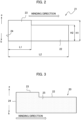
- FIG. 2 is a plan view of the positive electrode base 21 of the nickel-metal hydride secondary battery 1 shown in FIG. 1 .
- FIG. 3 is a plan view of the positive electrode 20 of the nickel-metal hydride secondary battery 1 shown in FIG. 1 .
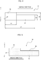
- FIG. 4 is a plan view of the negative electrode core 31 of the nickel-metal hydride secondary battery 1 shown in FIG. 1 .
- FIG. 5 is a plan view of the negative electrode 30 of the nickel-metal hydride secondary battery 1 shown in FIG. 1 .
- the arrow a indicates the upper side
- the arrow b indicates the lower side
- the upper side refers to the side where the positive terminal 70 of the battery 1 is provided
- the lower side refers to the side where the bottom wall 15 of the battery 1 is provided and the side opposite to the upper side.
- the direction perpendicular to the axis x hereinafter referred to as "radial direction"
- the direction away from the axis x is the radially outer side (the direction of the arrow c)
- the direction toward the axis x is the radially inner side (the direction of the arrow d).
- the battery 1 has an outer can 10 that is a bottomed cylindrical shape having an opening at the top (the direction of the arrow a).
- the outer can 10 is conductive, and the bottom wall 15 on the lower side (the direction of the arrow b) serves as the negative terminal.
- a sealing body 60 for sealing the outer can 10 is fixed to the opening of the outer can 10.
- This sealing body 60 is a conductive disc-shaped member.
- the sealing body 60 and an annular insulating gasket 12 surrounding the sealing body 60 are placed inside the opening of the outer can 10, and the insulating gasket 12 is fixed to the opening edge 13 of the outer can 10 by crimping the opening edge 13 of the outer can 10.
- the sealing body 60 and the insulating gasket 12 cooperate with each other to hermetically seal the opening of the outer can 10.
- the sealing body 60 has a central through hole 61 in the center, and a rubber valve 80 is located on the outer surface, the upper side of the sealing body 60, to plug the central through hole 61. Furthermore, a metal positive terminal 70 with a flange is electrically connected to the outer surface of the sealing body 60 so as to cover the valve 80. This positive terminal 70 pressurizes the valve 80 toward the sealing body 60. Note that the positive terminal 70 has a gas venting hole 71.
- the central through hole 61 is hermetically closed with the valve 80. Meanwhile, if gas is generated in the outer can 10 and the gas pressure increases, the valve 80 is compressed by the gas pressure to open the central through hole 61. As a result, gas is released from inside the outer can 10 through the central through hole 61 and the gas venting hole 71 of the positive terminal 70.
- the central through hole 61 of the sealing body 60, the valve 80, and the gas venting hole 71 of the positive terminal 70 are form a safety valve for the battery 1.
- the outer can 10 houses an electrode group 50.
- This electrode group 50 has a positive electrode 20 with a belt shape, negative electrode 30, and separator 40 are stacked on top of each other.
- the electrode group 50 is wound into a spiral shape with the separator 40 sandwiched between the positive electrode 20 and the negative electrode 30.
- the positive electrode 20 and the negative electrode 30 are stacked on top of each other with the separator 40 therebetween.
- a circular lower insulating member 17 is located between the electrode group 50 and the bottom wall 15 of the outer can 10.
- alkaline electrolyte (not shown in the drawing) has been filled into the outer can 10.
- This alkaline electrolyte is soaked into the electrode group 50 to promote an electrochemical reaction (charging and discharging reaction) during charging and discharging between the positive electrode 20 and the negative electrode 30.
- This alkaline electrolyte is preferably an aqueous solution containing at least one of KOH, NaOH, and LiOH as a solute.
- Examples of material for the separator 40 include polyamide fiber nonwoven fabric with hydrophilic functional groups, polyolefin fiber nonwoven fabric, such as polyethylene and polypropylene, with hydrophilic functional groups.
- the positive electrode 20 includes a positive electrode body 22 with a belt shape, and a positive electrode protrusion 23 protruding from a portion of the positive electrode body 22 toward the upper side of the sealing body 60 (in the direction of arrow a) to connect electrically to the sealing body 60.
- the positive electrode body 22 is a belt-shaped member having a predetermined height H2 along the up and down direction.
- the positive electrode protrusion 23 is a portion that extends upward from the winding beginning edge 24 of the positive electrode body 22 within a range up to a predetermined length L1 from the positive electrode body 22.
- the predetermined length L1 refers to the range of length of the positive electrode 20 in contact with the sealing body 60 in the state of the electrode group 50. To be specific, it refers to the range of length of the positive electrode 20 that is located on the inner side with respect to the insulating gasket 12 (in the direction of the arrow d) in the state of the electrode group 50.
- the positive electrode 20 has a height H1 greater than the height H2 of the positive electrode body 22 along the up and down direction.
- the positive electrode protrusion 23 is in contact with the sealing body 60.
- the positive electrode 20 is directly connected to the sealing body 60, which means that the positive terminal 70 and the positive electrode 20 are electrically connected to each other through the sealing body 60.
- the positive electrode 20 includes a conductive positive electrode base 21 having a porous structure and a positive electrode mixture 25 held in the pores of the positive electrode base 21.
- the positive electrode 20 has the positive electrode mixture 25, which serves as a positive electrode active material, in the portion facing the negative electrode 30, which is described below, with the separator 40 therebetween.
- the positive electrode mixture 25 is held over the entire surface (both sides) of the positive electrode base 21.
- Such a positive electrode base 21 can be, for example, a sheet of foamed nickel.
- the positive electrode mixture 25 contains positive electrode active material particles and a binding agent. Also, the positive electrode additive is added to the positive electrode mixture 25 as needed.
- a conductive and elastic connection member may be placed between the sealing body 60 and the positive electrode protrusion 23.
- the connection member may have a spiral shape corresponding to the shape of the positive electrode protrusion 23 shown in FIG. 1 , or may have a disc shape having a diameter equivalent or substantially equivalent to the outermost diameter of the positive electrode protrusion 23.
- the connection member which should electrically connect at least a part of the positive electrode protrusion 23 to the sealing body 60, may have any shape.
- the connection member may be a conductive member, such as a metallic foil or nickel sponge, attached to the periphery of an elastic member, such as rubber.
- the connection member is not necessarily as described above as an example and may be any member that has conductivity and elasticity.
- the aforementioned binding agent binds the positive electrode active material particles to each other and also binds the positive electrode active material particles to the positive electrode base 21.
- the binding agent include carboxymethylcellulose, methylcellulose, polytetrafluoroethylene (PTFE) dispersions, and hydroxypropyl cellulose (HPC) dispersions.
- the positive electrode additive include zinc oxide and cobalt hydroxide.
- the positive electrode active material particles are nickel hydroxide particles commonly used for nickel-metal hydride secondary batteries. It is preferable to use nickel hydroxide particles that are higher-order nickel hydroxide particles.
- the aforementioned positive electrode active material particles are produced by a manufacturing method commonly used for nickel-metal hydride secondary batteries.
- the positive electrode 20 can be manufactured, for example, in the following manner. First, a positive electrode base 21 molded into a predetermined shape is prepared ( FIG. 2 ). Meanwhile, a positive electrode mixture slurry containing positive electrode active material particles, water, and a binding agent is prepared. The prepared positive electrode mixture slurry is filled into a sheet of foamed nickel serving as the positive electrode base 21 and is dried. After drying, the sheet of foamed nickel filled with nickel hydroxide particles and the like is rolled and then cut to produce the positive electrode 20 ( FIG. 3 ).
- the negative electrode 30 includes a negative electrode body 32 with a belt shape and a negative electrode protrusion 33 that protrudes from a portion of the negative electrode body 32 upward or toward the sealing body 60 to terminate between the sealing body 60 and the negative electrode body 32.
- the negative electrode body 32 is a belt-shaped member having a predetermined height H3 along the up and down direction.
- the negative electrode protrusion 33 is a portion that extends upward from the winding beginning edge 34 of the negative electrode body 32 within a range up to a predetermined length L3 from the negative electrode body 32.
- the predetermined length L3 refers to the range of length of the negative electrode 30 facing the positive electrode protrusion 23 of the positive electrode 20 in the state of the electrode group 50.
- the negative electrode 30 has a height H3 greater than the height H4 of the negative electrode body 32 along the up and down direction.
- the negative electrode protrusion 33 is not in contact with the sealing body 60. In other words, the negative electrode 30 is not connected to the sealing body 60.
- the negative electrode 30 has a metal negative electrode core 31 and a negative electrode mixture 35 containing the negative electrode active material held on the negative electrode core 31.
- the negative electrode core 31 is conductive.
- the negative electrode 30 has the negative electrode active material in the portion facing the positive electrode 20 with the separator 40 therebetween.
- the negative electrode mixture 35 is held over the entire surface (both sides) of the negative electrode core 31.
- the negative electrode 30 is electrically connected to the outer can 10 in a state where it is in contact with the inner periphery of the outer can 10 serving as the negative terminal of the nickel-metal hydride secondary battery 1.
- the negative electrode core 31 is a belt-shaped metal material with through holes (not shown in the drawing) distributed, and may be, for example, a perforated metal sheet.
- the negative electrode mixture 35 is a negative electrode mixture containing a negative electrode active material.
- the negative electrode mixture 35 is not only filled into the through holes of the negative electrode core 31, but is also layered on the top and rear surfaces of the negative electrode core 31, forming a layer of negative electrode mixture 35.
- the negative electrode mixture 35 contains hydrogen storage alloy particles that can absorb and release hydrogen as the negative electrode active material, a conductive agent, a binding agent, and a negative electrode auxiliary agent.
- the aforementioned binding agent binds the hydrogen storage alloy particles, conductive agent, and the like together and also binds the hydrogen storage alloy particles, conductive agent, and the like to the negative electrode core 31.
- the binding agent is not particularly limited, and may be chosen from any binding agents that are commonly used for nickel-metal hydride secondary batteries, such as hydrophilic or hydrophobic polymers, and carboxymethylcellulose, for example.
- the negative electrode auxiliary agent may be styrene butadiene rubber, sodium polyacrylate, or the like.
- the hydrogen absorbing alloy for the hydrogen storage alloy particles is not particularly limited, and is preferably one commonly used in nickel-metal hydride secondary batteries.
- the conductive agent is one commonly used for negative electrodes of nickel-metal hydride secondary batteries. For example, carbon black is used.
- the negative electrode 30 can be manufactured, for example, in the following manner. First, prepare a negative electrode core 31 molded into a predetermined shape ( FIG. 4 ). Meanwhile, hydrogen absorbing alloy powder, which is an aggregate of hydrogen storage alloy particles described above, a conductive agent, a binding agent, and water are prepared, and these are blended to prepare a paste of negative electrode mixture. The resulting paste is applied to the negative electrode core 31 and then dried. After drying, the density of the negative electrode mixture 35 is adjusted to a predetermined value in a rolling step in which the negative electrode 30 is entirely rolled. The negative electrode 30 is produced in this way.
- the positive electrode 20 and negative electrode 30 produced as described above are wound together into a spiral shape with the separator 40 therebetween, forming an electrode group 50.
- the electrode group 50 obtained in this manner is housed in the outer can 10.
- a predetermined amount of alkaline electrolyte is filled into the outer can 10.
- the outer can 10 containing the electrode group 50 and the alkaline electrolyte is sealed with a sealing body 60 that has the positive terminal 70, yielding a battery 1 according to the embodiment.
- the battery 1 is subjected to an initial activation process to be made ready for use.
- the positive electrode 20 includes a positive electrode body 22 with a belt shape and a positive electrode protrusion 23 that protrudes from a portion of the positive electrode body 22 toward the sealing body 60 to connect electrically to the sealing body 60.
- the negative electrode 30 includes a negative electrode body 32 with a belt shape and a negative electrode protrusion 33 that protrudes from a portion of the negative electrode body 32 toward the sealing body 60 and is terminated between the sealing body 60 and the negative electrode body 32.
- the positive electrode 20 and the negative electrode 30 have a positive electrode active material and a negative electrode active material, respectively, in portions facing each other with the separator 40 therebetween.
- the positive electrode 20 and the negative electrode 30 have a positive electrode protrusion 23 and a negative electrode protrusion 33 separately from a positive electrode body 22 and a negative electrode body 32, and have a positive electrode active material and a negative electrode active material, respectively, in portions facing each other with the separator 40 therebetween.
- making part of the positive electrode 20 and the negative electrode 30 longer in the height direction (in the direction of the axis x of the outer can 10) allows the battery 1 to have higher capacity without making the electrode group 50 thicker in the thickness direction (the radial direction of the outer can 10).
- This also eliminates the need for thinning the separator 40 for increasing the capacity of the battery 1, thereby suppressing breaking through of the separator 40 due to burrs on the positive electrode 20 and the negative electrode 30 and thus suppressing short-circuits inside the battery 1. In this way, a battery 1 that can achieve high capacity while suppressing the occurrence of internal short-circuits can be provided.
- the battery 1 according to the embodiment further includes a conductive and elastic connection member between the sealing body 60 and the positive electrode protrusion 23.
- a conductive and elastic connection member between the sealing body 60 and the positive electrode protrusion 23.
- Table 1 below shows a comparison between the number of short-circuits and discharge capacity for the battery of Example and that of Comparative Examples 1 and 2, where 100 cells were manufactured for each battery.
- the test conditions were as follows: charge time was "0.1C ⁇ 16H", pause time was “1H”, and discharge time was "0.2C”.
- C refers to the speed of charging and discharging
- 1C refers to the current value for full charge or full discharge in 1H.
- it is charged for 16H at a charging speed at which it is fully charged in 10 hours, and following a pause of 1H, it is discharged at a discharging speed of 5 hours for full discharge.
- the numeric data in Table 1 is shown as that compared with reference to the experimental values in Example.
- the battery height i.e., the distance between the bottom surface of the bottom wall 15 and the top surface of the positive terminal 70 in the direction of the axis x in FIG. 1 , is Reference "1".
- the battery height of Comparative Examples 1 and 2 is equal to the battery height of Example.
- Example the total length of the positive electrode 20, L2 (see FIG. 2 ), is Reference "1".
- the total length of the positive electrodes of Comparative Examples 1 and 2 is equal to the total length of the positive electrode 20 of Example.
- L1:L2 1:1.72.
- the height of the positive electrodes of Comparative Examples 1 and 2 is equal to the height H2 of the positive electrode body 22 of Example. In other words, the positive electrodes of Comparative Examples 1 and 2 have a rectangular shape with the length L2 and height H2.
- the thickness of the positive electrode 20, i.e., the thickness including the positive electrode base 21 and the positive electrode mixture 25, is Reference "1".
- the thickness of the positive electrode of Comparative Example 1 is equal to the thickness of the positive electrode 20 of Example, and the thickness of the positive electrode of Comparative Example 2 is "1.02" unlike the thickness of the positive electrode 20 of Example.
- Comparative Example 2 more positive electrode mixture than the amount of positive electrode mixture in Example was applied.
- a positive electrode base molded into a predetermined shape is prepared ( FIG. 2 ). Meanwhile, a positive electrode mixture slurry containing positive electrode active material particles, water, and a binding agent is prepared. The prepared positive electrode mixture slurry is filled into a sheet of foamed nickel as the positive electrode base and is dried. After drying, the sheet of foamed nickel filled with nickel hydroxide particles and the like is rolled and then cut to produce a positive electrode. One hundred cells of such positive electrodes were manufactured ( FIG. 3 ).
- Example the total length of the negative electrode 30, L4 (see FIG. 4 ), is Reference "1".
- the total length of the negative electrodes of Comparative Examples 1 and 2 is equal to the total length of the negative electrode 30 of Example.
- the height of the negative electrode i.e., the height H3 ( FIG. 4 ) of the negative electrode body 32
- the height H4 ( FIG. 4 ) at the negative electrode protrusion 33 of the negative electrode 30 is "1.04".
- L3:L4 1:2.72.
- the height of the negative electrodes of Comparative Examples 1 and 2 is equal to the height H3 of the negative electrode body 32 of Example. In other words, the negative electrodes of Comparative Examples 1 and 2 have a rectangular shape with the length L4 and height H3.
- the thickness of the negative electrode 30, i.e., the thickness including the negative electrode core 31 and the negative electrode mixture 35, is Reference “1".
- the thickness of the negative electrode of Comparative Example 1 is equal to the thickness of the negative electrode 30 of Example, and the thickness of the negative electrode of Comparative Example 2 is "1.02" unlike the thickness of the negative electrode 30 of Example.
- Comparative Example 2 more negative electrode mixture than the amount of negative electrode mixture in Example was applied.
- a negative electrode core molded into a predetermined shape is prepared ( FIG. 4 ).
- hydrogen absorbing alloy powder which is an aggregate of hydrogen storage alloy particles described above, a conductive agent, a binding agent, and water are prepared, and these are blended to prepare a paste of negative electrode mixture.
- the resulting paste is applied to the negative electrode core and then dried. After drying, the density of the negative electrode mixture is adjusted to a predetermined value in a rolling step in which the negative electrode is entirely rolled, and the negative electrode is then produced.
- One hundred cells of such positive electrodes were manufactured.
- the positive electrode and negative electrode produced as described above are wound together into a spiral shape with the separator therebetween, forming a spiral electrode group.
- the electrode group obtained in this manner is housed in the outer can.
- a predetermined amount of alkaline electrolyte is filled into the outer can.
- the outer can containing the electrode group and the alkaline electrolyte is sealed with a sealing body that has a positive terminal, yielding a battery.
- the battery is subjected to an initial activation process to be made ready for use.
- the battery thus manufactured was subjected to the test conditions described above, and the results shown in Table 1 above were obtained. As shown in Table 1 above, it was confirmed that the battery of Example has a larger discharge capacity than the battery of Comparative Example 1 and fewer short-circuits than the battery of Comparative Example 2.
- the present invention is not limited to the nickel-metal hydride secondary battery 1 of the embodiments, but includes all aspects included in the concept and claims of the present invention, and the configurations may be selectively combined as appropriate.
- the shape, material, position, size, and the like of each component in the embodiments may be changed as appropriate depending on the specific mode of the invention.
Landscapes
- Chemical & Material Sciences (AREA)
- Chemical Kinetics & Catalysis (AREA)
- Electrochemistry (AREA)
- General Chemical & Material Sciences (AREA)
- Engineering & Computer Science (AREA)
- Manufacturing & Machinery (AREA)
- Secondary Cells (AREA)
- Connection Of Batteries Or Terminals (AREA)
- Battery Electrode And Active Subsutance (AREA)
- Cell Electrode Carriers And Collectors (AREA)
Applications Claiming Priority (2)
| Application Number | Priority Date | Filing Date | Title |
|---|---|---|---|
| JP2020051202A JP7488008B2 (ja) | 2020-03-23 | 2020-03-23 | アルカリ蓄電池 |
| PCT/JP2021/009101 WO2021192978A1 (fr) | 2020-03-23 | 2021-03-09 | Batterie de stockage alcaline |
Publications (2)
| Publication Number | Publication Date |
|---|---|
| EP4131559A1 true EP4131559A1 (fr) | 2023-02-08 |
| EP4131559A4 EP4131559A4 (fr) | 2024-05-01 |
Family
ID=77849389
Family Applications (1)
| Application Number | Title | Priority Date | Filing Date |
|---|---|---|---|
| EP21775650.1A Pending EP4131559A4 (fr) | 2020-03-23 | 2021-03-09 | Batterie de stockage alcaline |
Country Status (5)
| Country | Link |
|---|---|
| US (1) | US20230112329A1 (fr) |
| EP (1) | EP4131559A4 (fr) |
| JP (1) | JP7488008B2 (fr) |
| CN (1) | CN115336077A (fr) |
| WO (1) | WO2021192978A1 (fr) |
Families Citing this family (3)
| Publication number | Priority date | Publication date | Assignee | Title |
|---|---|---|---|---|
| US20220352555A1 (en) * | 2021-05-02 | 2022-11-03 | Bell Textron Inc. | Lightweight battery cell assembly |
| US11935996B2 (en) | 2021-05-02 | 2024-03-19 | Textron Innovations Inc. | Thermally efficient battery cell assembly |
| CN219203434U (zh) * | 2022-12-29 | 2023-06-16 | 远景动力技术(江苏)有限公司 | 一种圆柱电池及电子设备 |
Family Cites Families (15)
| Publication number | Priority date | Publication date | Assignee | Title |
|---|---|---|---|---|
| JPS5125693Y2 (fr) * | 1971-11-10 | 1976-06-30 | ||
| US5587259A (en) * | 1994-03-09 | 1996-12-24 | Rayovac Corporation | Metal-air cathode and cell having a hardened current collecting substrate |
| US5491038A (en) * | 1994-08-24 | 1996-02-13 | Duracell Inc. | Contact ring for on-cell battery tester |
| US5698176A (en) * | 1995-06-07 | 1997-12-16 | Duracell, Inc. | Manganese dioxide for lithium batteries |
| JPH11144761A (ja) * | 1997-11-10 | 1999-05-28 | Toyota Motor Corp | リチウムイオン2次電池 |
| JPH11213983A (ja) * | 1998-01-22 | 1999-08-06 | Shin Kobe Electric Mach Co Ltd | 円筒型電池 |
| JP3334683B2 (ja) * | 1999-06-28 | 2002-10-15 | エヌイーシートーキン株式会社 | 非水電解液二次電池およびその製造方法 |
| JP2004022320A (ja) | 2002-06-17 | 2004-01-22 | Yuasa Corp | 電池 |
| FR2905525B1 (fr) * | 2006-09-05 | 2008-10-31 | Accumulateurs Fixes | Dispositif de raccordement electrique pour borne de sortie d'un accumulateur de courant |
| CN105186028B (zh) * | 2010-02-23 | 2017-08-04 | Tdk株式会社 | 电化学装置以及电化学装置的制造方法 |
| JP2015125869A (ja) | 2013-12-26 | 2015-07-06 | Fdk株式会社 | アルカリ二次電池 |
| JP6258180B2 (ja) * | 2014-10-16 | 2018-01-10 | 株式会社日立製作所 | リチウム二次電池用電解液の添加剤及びそれを用いたリチウム二次電池用電解液、リチウム二次電池 |
| WO2018116574A1 (fr) * | 2016-12-19 | 2018-06-28 | パナソニックIpマネジメント株式会社 | Batterie alcaline de stockage |
| JP6876426B2 (ja) * | 2016-12-21 | 2021-05-26 | Fdk株式会社 | アルカリ二次電池 |
| CN110034326A (zh) * | 2019-04-08 | 2019-07-19 | 江苏金赛尔电池科技有限公司 | 一种无极耳的锂电池及其制备方法 |
-
2020
- 2020-03-23 JP JP2020051202A patent/JP7488008B2/ja active Active
-
2021
- 2021-03-09 US US17/905,257 patent/US20230112329A1/en active Pending
- 2021-03-09 WO PCT/JP2021/009101 patent/WO2021192978A1/fr not_active Ceased
- 2021-03-09 EP EP21775650.1A patent/EP4131559A4/fr active Pending
- 2021-03-09 CN CN202180022915.0A patent/CN115336077A/zh active Pending
Also Published As
| Publication number | Publication date |
|---|---|
| WO2021192978A1 (fr) | 2021-09-30 |
| US20230112329A1 (en) | 2023-04-13 |
| CN115336077A (zh) | 2022-11-11 |
| JP7488008B2 (ja) | 2024-05-21 |
| EP4131559A4 (fr) | 2024-05-01 |
| JP2021150242A (ja) | 2021-09-27 |
Similar Documents
| Publication | Publication Date | Title |
|---|---|---|
| EP2472641A1 (fr) | Batterie au nickel-zinc et son procédé de fabrication | |
| EP4131559A1 (fr) | Batterie de stockage alcaline | |
| WO2006035980A1 (fr) | Batterie a boitier, fil de batterie a boitier, et ensemble batterie forme d'une pluralite de batteries a boitier | |
| JP4727004B2 (ja) | 円筒型電池 | |
| US11038238B2 (en) | Alkaline secondary battery | |
| CN1960050B (zh) | 圆筒型碱性蓄电池 | |
| JP5110889B2 (ja) | ニッケル水素二次電池 | |
| EP4478473A1 (fr) | Batterie au zinc | |
| KR100210502B1 (ko) | 권취극판군용 세퍼레이터 | |
| JP6151106B2 (ja) | ニッケル水素蓄電池 | |
| JP7197251B2 (ja) | アルカリ二次電池 | |
| JP3706166B2 (ja) | ニッケル水素二次電池の製造方法 | |
| JP2022124195A (ja) | アルカリ蓄電池 | |
| US12482820B2 (en) | Negative electrode for alkaline storage battery and alkaline storage battery including the negative electrode | |
| JP7791117B2 (ja) | 円筒型アルカリ蓄電池 | |
| CN115084455B (zh) | 碱性充电电池用电极和碱性充电电池 | |
| JP2013012349A (ja) | アルカリ蓄電池 | |
| CN108039522B (zh) | 一种低自放电镍氢电池及其制造方法 | |
| JP7093199B2 (ja) | 封口体及び電池 | |
| JP2021089851A (ja) | アルカリ蓄電池 | |
| JP2004119280A (ja) | 電池およびその製造方法 | |
| JP2001176540A (ja) | ニッケル水素二次電池 | |
| KR980012670A (ko) | 밀폐형 전지용 캡 어셈블리 | |
| KR19980015696A (ko) | 세퍼레이터의 제조방법 |
Legal Events
| Date | Code | Title | Description |
|---|---|---|---|
| STAA | Information on the status of an ep patent application or granted ep patent |
Free format text: STATUS: THE INTERNATIONAL PUBLICATION HAS BEEN MADE |
|
| PUAI | Public reference made under article 153(3) epc to a published international application that has entered the european phase |
Free format text: ORIGINAL CODE: 0009012 |
|
| STAA | Information on the status of an ep patent application or granted ep patent |
Free format text: STATUS: REQUEST FOR EXAMINATION WAS MADE |
|
| 17P | Request for examination filed |
Effective date: 20220916 |
|
| AK | Designated contracting states |
Kind code of ref document: A1 Designated state(s): AL AT BE BG CH CY CZ DE DK EE ES FI FR GB GR HR HU IE IS IT LI LT LU LV MC MK MT NL NO PL PT RO RS SE SI SK SM TR |
|
| DAV | Request for validation of the european patent (deleted) | ||
| DAX | Request for extension of the european patent (deleted) | ||
| A4 | Supplementary search report drawn up and despatched |
Effective date: 20240403 |
|
| RIC1 | Information provided on ipc code assigned before grant |
Ipc: H01M 50/586 20210101ALI20240326BHEP Ipc: H01M 50/538 20210101ALI20240326BHEP Ipc: H01M 50/107 20210101ALI20240326BHEP Ipc: H01M 4/24 20060101ALI20240326BHEP Ipc: H01M 10/34 20060101ALI20240326BHEP Ipc: H01M 50/545 20210101ALI20240326BHEP Ipc: H01M 50/186 20210101ALI20240326BHEP Ipc: H01M 50/184 20210101ALI20240326BHEP Ipc: H01M 50/152 20210101ALI20240326BHEP Ipc: H01M 50/534 20210101ALI20240326BHEP Ipc: H01M 50/531 20210101ALI20240326BHEP Ipc: H01M 10/28 20060101AFI20240326BHEP |