EP4131564A1 - Stromquellenvorrichtung und fahrzeug sowie energiespeichervorrichtung damit - Google Patents
Stromquellenvorrichtung und fahrzeug sowie energiespeichervorrichtung damit Download PDFInfo
- Publication number
- EP4131564A1 EP4131564A1 EP21779229.0A EP21779229A EP4131564A1 EP 4131564 A1 EP4131564 A1 EP 4131564A1 EP 21779229 A EP21779229 A EP 21779229A EP 4131564 A1 EP4131564 A1 EP 4131564A1
- Authority
- EP
- European Patent Office
- Prior art keywords
- power source
- source device
- cover
- fastening
- battery
- Prior art date
- Legal status (The legal status is an assumption and is not a legal conclusion. Google has not performed a legal analysis and makes no representation as to the accuracy of the status listed.)
- Pending
Links
- 238000003860 storage Methods 0.000 title claims description 25
- 230000008878 coupling Effects 0.000 claims abstract description 23
- 238000010168 coupling process Methods 0.000 claims abstract description 23
- 238000005859 coupling reaction Methods 0.000 claims abstract description 23
- 238000005452 bending Methods 0.000 claims abstract description 9
- 238000007600 charging Methods 0.000 claims description 32
- 238000007599 discharging Methods 0.000 claims description 14
- 239000011324 bead Substances 0.000 claims description 7
- 239000007789 gas Substances 0.000 description 112
- 230000002787 reinforcement Effects 0.000 description 40
- 238000004891 communication Methods 0.000 description 37
- 229910052751 metal Inorganic materials 0.000 description 18
- 239000002184 metal Substances 0.000 description 18
- 125000006850 spacer group Chemical group 0.000 description 17
- 239000011347 resin Substances 0.000 description 11
- 229920005989 resin Polymers 0.000 description 11
- 230000008961 swelling Effects 0.000 description 11
- 238000007789 sealing Methods 0.000 description 10
- 238000005192 partition Methods 0.000 description 8
- 238000009413 insulation Methods 0.000 description 5
- 230000008602 contraction Effects 0.000 description 4
- 239000011810 insulating material Substances 0.000 description 4
- 239000000463 material Substances 0.000 description 4
- 238000010248 power generation Methods 0.000 description 4
- 230000002522 swelling effect Effects 0.000 description 4
- 229910052782 aluminium Inorganic materials 0.000 description 3
- XAGFODPZIPBFFR-UHFFFAOYSA-N aluminium Chemical compound [Al] XAGFODPZIPBFFR-UHFFFAOYSA-N 0.000 description 3
- 238000010586 diagram Methods 0.000 description 3
- 230000005611 electricity Effects 0.000 description 3
- 230000003014 reinforcing effect Effects 0.000 description 3
- 229910000838 Al alloy Inorganic materials 0.000 description 2
- 229920006257 Heat-shrinkable film Polymers 0.000 description 2
- XEEYBQQBJWHFJM-UHFFFAOYSA-N Iron Chemical compound [Fe] XEEYBQQBJWHFJM-UHFFFAOYSA-N 0.000 description 2
- 229910045601 alloy Inorganic materials 0.000 description 2
- 239000000956 alloy Substances 0.000 description 2
- 230000001413 cellular effect Effects 0.000 description 2
- 230000000694 effects Effects 0.000 description 2
- 230000001172 regenerating effect Effects 0.000 description 2
- RYGMFSIKBFXOCR-UHFFFAOYSA-N Copper Chemical compound [Cu] RYGMFSIKBFXOCR-UHFFFAOYSA-N 0.000 description 1
- HBBGRARXTFLTSG-UHFFFAOYSA-N Lithium ion Chemical compound [Li+] HBBGRARXTFLTSG-UHFFFAOYSA-N 0.000 description 1
- PXHVJJICTQNCMI-UHFFFAOYSA-N Nickel Chemical compound [Ni] PXHVJJICTQNCMI-UHFFFAOYSA-N 0.000 description 1
- 229910000831 Steel Inorganic materials 0.000 description 1
- 230000001133 acceleration Effects 0.000 description 1
- 230000015572 biosynthetic process Effects 0.000 description 1
- 230000000903 blocking effect Effects 0.000 description 1
- OJIJEKBXJYRIBZ-UHFFFAOYSA-N cadmium nickel Chemical compound [Ni].[Cd] OJIJEKBXJYRIBZ-UHFFFAOYSA-N 0.000 description 1
- 230000015556 catabolic process Effects 0.000 description 1
- 239000011248 coating agent Substances 0.000 description 1
- 238000000576 coating method Methods 0.000 description 1
- 230000000052 comparative effect Effects 0.000 description 1
- 239000000470 constituent Substances 0.000 description 1
- 239000000112 cooling gas Substances 0.000 description 1
- 229910052802 copper Inorganic materials 0.000 description 1
- 239000010949 copper Substances 0.000 description 1
- 238000005520 cutting process Methods 0.000 description 1
- 238000006731 degradation reaction Methods 0.000 description 1
- 238000006073 displacement reaction Methods 0.000 description 1
- 238000009826 distribution Methods 0.000 description 1
- 239000008151 electrolyte solution Substances 0.000 description 1
- 239000000446 fuel Substances 0.000 description 1
- 230000001771 impaired effect Effects 0.000 description 1
- 229910052742 iron Inorganic materials 0.000 description 1
- 229910001416 lithium ion Inorganic materials 0.000 description 1
- 230000007257 malfunction Effects 0.000 description 1
- 150000002739 metals Chemical class 0.000 description 1
- 238000000034 method Methods 0.000 description 1
- 238000000465 moulding Methods 0.000 description 1
- 229910000652 nickel hydride Inorganic materials 0.000 description 1
- 239000003973 paint Substances 0.000 description 1
- 230000002093 peripheral effect Effects 0.000 description 1
- 229920000515 polycarbonate Polymers 0.000 description 1
- 239000004417 polycarbonate Substances 0.000 description 1
- 230000002265 prevention Effects 0.000 description 1
- 238000004080 punching Methods 0.000 description 1
- 238000010008 shearing Methods 0.000 description 1
- 229920006300 shrink film Polymers 0.000 description 1
- 239000000243 solution Substances 0.000 description 1
- 239000010959 steel Substances 0.000 description 1
Images







Classifications
-
- H—ELECTRICITY
- H01—ELECTRIC ELEMENTS
- H01M—PROCESSES OR MEANS, e.g. BATTERIES, FOR THE DIRECT CONVERSION OF CHEMICAL ENERGY INTO ELECTRICAL ENERGY
- H01M50/00—Constructional details or processes of manufacture of the non-active parts of electrochemical cells other than fuel cells, e.g. hybrid cells
- H01M50/20—Mountings; Secondary casings or frames; Racks, modules or packs; Suspension devices; Shock absorbers; Transport or carrying devices; Holders
- H01M50/204—Racks, modules or packs for multiple batteries or multiple cells
- H01M50/207—Racks, modules or packs for multiple batteries or multiple cells characterised by their shape
- H01M50/209—Racks, modules or packs for multiple batteries or multiple cells characterised by their shape adapted for prismatic or rectangular cells
-
- H—ELECTRICITY
- H01—ELECTRIC ELEMENTS
- H01M—PROCESSES OR MEANS, e.g. BATTERIES, FOR THE DIRECT CONVERSION OF CHEMICAL ENERGY INTO ELECTRICAL ENERGY
- H01M50/00—Constructional details or processes of manufacture of the non-active parts of electrochemical cells other than fuel cells, e.g. hybrid cells
- H01M50/20—Mountings; Secondary casings or frames; Racks, modules or packs; Suspension devices; Shock absorbers; Transport or carrying devices; Holders
- H01M50/204—Racks, modules or packs for multiple batteries or multiple cells
-
- H—ELECTRICITY
- H01—ELECTRIC ELEMENTS
- H01M—PROCESSES OR MEANS, e.g. BATTERIES, FOR THE DIRECT CONVERSION OF CHEMICAL ENERGY INTO ELECTRICAL ENERGY
- H01M10/00—Secondary cells; Manufacture thereof
- H01M10/42—Methods or arrangements for servicing or maintenance of secondary cells or secondary half-cells
- H01M10/44—Methods for charging or discharging
-
- H—ELECTRICITY
- H01—ELECTRIC ELEMENTS
- H01M—PROCESSES OR MEANS, e.g. BATTERIES, FOR THE DIRECT CONVERSION OF CHEMICAL ENERGY INTO ELECTRICAL ENERGY
- H01M50/00—Constructional details or processes of manufacture of the non-active parts of electrochemical cells other than fuel cells, e.g. hybrid cells
- H01M50/20—Mountings; Secondary casings or frames; Racks, modules or packs; Suspension devices; Shock absorbers; Transport or carrying devices; Holders
- H01M50/262—Mountings; Secondary casings or frames; Racks, modules or packs; Suspension devices; Shock absorbers; Transport or carrying devices; Holders with fastening means, e.g. locks
-
- H—ELECTRICITY
- H01—ELECTRIC ELEMENTS
- H01M—PROCESSES OR MEANS, e.g. BATTERIES, FOR THE DIRECT CONVERSION OF CHEMICAL ENERGY INTO ELECTRICAL ENERGY
- H01M50/00—Constructional details or processes of manufacture of the non-active parts of electrochemical cells other than fuel cells, e.g. hybrid cells
- H01M50/20—Mountings; Secondary casings or frames; Racks, modules or packs; Suspension devices; Shock absorbers; Transport or carrying devices; Holders
- H01M50/262—Mountings; Secondary casings or frames; Racks, modules or packs; Suspension devices; Shock absorbers; Transport or carrying devices; Holders with fastening means, e.g. locks
- H01M50/264—Mountings; Secondary casings or frames; Racks, modules or packs; Suspension devices; Shock absorbers; Transport or carrying devices; Holders with fastening means, e.g. locks for cells or batteries, e.g. straps, tie rods or peripheral frames
-
- H—ELECTRICITY
- H01—ELECTRIC ELEMENTS
- H01M—PROCESSES OR MEANS, e.g. BATTERIES, FOR THE DIRECT CONVERSION OF CHEMICAL ENERGY INTO ELECTRICAL ENERGY
- H01M50/00—Constructional details or processes of manufacture of the non-active parts of electrochemical cells other than fuel cells, e.g. hybrid cells
- H01M50/20—Mountings; Secondary casings or frames; Racks, modules or packs; Suspension devices; Shock absorbers; Transport or carrying devices; Holders
- H01M50/271—Lids or covers for the racks or secondary casings
-
- H—ELECTRICITY
- H01—ELECTRIC ELEMENTS
- H01M—PROCESSES OR MEANS, e.g. BATTERIES, FOR THE DIRECT CONVERSION OF CHEMICAL ENERGY INTO ELECTRICAL ENERGY
- H01M50/00—Constructional details or processes of manufacture of the non-active parts of electrochemical cells other than fuel cells, e.g. hybrid cells
- H01M50/30—Arrangements for facilitating escape of gases
-
- H—ELECTRICITY
- H01—ELECTRIC ELEMENTS
- H01M—PROCESSES OR MEANS, e.g. BATTERIES, FOR THE DIRECT CONVERSION OF CHEMICAL ENERGY INTO ELECTRICAL ENERGY
- H01M50/00—Constructional details or processes of manufacture of the non-active parts of electrochemical cells other than fuel cells, e.g. hybrid cells
- H01M50/50—Current conducting connections for cells or batteries
- H01M50/502—Interconnectors for connecting terminals of adjacent batteries; Interconnectors for connecting cells outside a battery casing
- H01M50/505—Interconnectors for connecting terminals of adjacent batteries; Interconnectors for connecting cells outside a battery casing comprising a single busbar
-
- H—ELECTRICITY
- H01—ELECTRIC ELEMENTS
- H01M—PROCESSES OR MEANS, e.g. BATTERIES, FOR THE DIRECT CONVERSION OF CHEMICAL ENERGY INTO ELECTRICAL ENERGY
- H01M2220/00—Batteries for particular applications
- H01M2220/20—Batteries in motive systems, e.g. vehicle, ship, plane
-
- Y—GENERAL TAGGING OF NEW TECHNOLOGICAL DEVELOPMENTS; GENERAL TAGGING OF CROSS-SECTIONAL TECHNOLOGIES SPANNING OVER SEVERAL SECTIONS OF THE IPC; TECHNICAL SUBJECTS COVERED BY FORMER USPC CROSS-REFERENCE ART COLLECTIONS [XRACs] AND DIGESTS
- Y02—TECHNOLOGIES OR APPLICATIONS FOR MITIGATION OR ADAPTATION AGAINST CLIMATE CHANGE
- Y02E—REDUCTION OF GREENHOUSE GAS [GHG] EMISSIONS, RELATED TO ENERGY GENERATION, TRANSMISSION OR DISTRIBUTION
- Y02E60/00—Enabling technologies; Technologies with a potential or indirect contribution to GHG emissions mitigation
- Y02E60/10—Energy storage using batteries
Definitions
- the present disclosure relates to a power source device, and vehicle and an electrical storage device each equipped with the same.
- a power source device such as a battery module or a battery pack including a plurality of battery cells is used as a power source for a vehicle such as a hybrid vehicle or an electric car, a power source for a power storage system for a factory, a home, or the like (see PTL 1, for example).
- Such a power source device has a plurality of chargeable and dischargeable battery cells that are stacked.
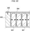
- end plate 903 is disposed on each of both end surfaces of battery stack 910 in which battery cell 901 with a prismatic outer covering can and insulating spacer 902 are alternately stacked, and end plates 903 are fastened to each other with metallic bind bar 904.
- Each bind bar 904 is fixed to end plate 903 by bolt 905.
- the outer covering When the battery cell is repeatedly charged and discharged, the outer covering can swells and contracts. In particular, with the recent demand for higher capacity, the capacity of each secondary battery cell is increasing. As a result, the swelling amount tends to increase. In a battery stack in which a large number of such secondary battery cells are stacked and fastened, the swelling force of the secondary battery cells increases, and the swelling amount also increases in accordance with the number of secondary battery cells.
- the bind bar is also required to have high rigidity so as to cope with such swelling of the secondary battery cell.
- An object of one aspect of the present invention is to provide a power source device that suppresses occurrence of bolt slippage and enhances safety, and a vehicle and an electrical storage device equipped with the power source device.
- a power source device even when the battery stack swells and contracts, the swelling and contraction are absorbed by two bent parts with the intermediate part interposed therebetween, occurrence of bolt slippage can be suppressed, and hence the fixed state between the fastening member and the end plate can be maintained with high reliability.
- Exemplary embodiments of the present invention may be specified by the following configurations.
- a power source device includes, in addition to the above configuration, the fastening body and the coupling piece are arranged in parallel with different heights.
- the fastening member is formed such that the coupling piece is narrower in width than the fastening main surface.
- the above configuration can reduce the section modulus, and can suppress a situation in which deformation due to swelling and contraction of the battery stack reaches the coupling piece.
- a power source device further includes, in addition to any of the configurations described above: a first cover that is provided on an upper surface of the battery stack and opens at a position corresponding to the gas discharge valve; and a second cover that is provided on an upper surface of the first cover and defines a gas duct with the first cover, in which the fastening member includes a metallic third cover that is provided on an upper surface of a second cove and abuts on an upper surface of the second cover.
- the gas duct forms a baffle plate between the first cover and a second cover.
- the third cover is fixed to the end plate.
- the above configuration makes it possible to firmly fix the third cover to the power source device using the end plate, and the third cover can prevent deformation of the second cover.
- a power source device further includes, in addition to any of the configurations described above, a bus bar that connects electrode terminals of the battery cells constituting the battery stack; and a total terminal strip that is connected to the bus bar, in which the third cover forms an exposure part that exposes the total terminal strip.
- the third cover forms a bead.
- the strength can be improved by simple processing of forming a bead on the third cover.
- an electric vehicle includes: any one of the above-described power source devices; a travel motor to which electric power is supplied from the power source device; a vehicle main body on which the power source device and the motor are mounted; and wheels that are driven by the motor to make the vehicle main body travel.
- an electrical storage device includes any of the above power source devices and a power supply controller that controls charging and discharging of the power source device, in which the power supply controller enables charging of the plurality of battery cells with electric power from outside, and controls charging to be performed on the plurality of battery cells.
- the elements constituting the present invention may be configured such that the plurality of elements are constituted of the same members to form one member that functions as a plurality of elements, or conversely, the function of one member can be shared and achieved by a plurality of members.
- the description in some examples or exemplary embodiments may be applied to other examples, exemplary embodiments, and the like.
- the power source device is used in various applications including a power source to be equipped on a hybrid vehicle, an electric car, or other electric vehicles to supply electric power to a drive motor, a power source that stores power generated by natural energy such as solar power generation and wind power generation, and a power source for storing midnight electric power, and in particular, used as a power source suitable for large-power, large-current applications.
- a power source to be equipped on a hybrid vehicle an electric car, or other electric vehicles to supply electric power to a drive motor
- a power source that stores power generated by natural energy such as solar power generation and wind power generation
- a power source for storing midnight electric power and in particular, used as a power source suitable for large-power, large-current applications.
- the exemplary embodiments applied to a power source device for driving an electric vehicle will be described.
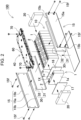
- FIG. 1 is an exploded perspective view with an enlarged view of a main part of power source device 100 according to a first exemplary embodiment
- Fig. 2 is an exploded perspective view of power source device 100 shown in Fig. 1 .
- Power source device 100 shown in these figures includes battery stack 10 in which the plurality of battery cells 1 are stacked, a pair of end plates 20 covering both end surfaces of battery stack 10, a plurality of fastening members 15 for fastening end plates 20 to each other, and cover assembly 40 provided on an upper surface of battery stack 10.
- Fastening member 15 is formed into a plate shape extending along a stack direction of the plurality of battery cells 1. Fastening members 15 are arranged on opposite side surfaces of battery stack 10 to fasten end plates 20 to each other.
- battery stack 10 includes the plurality of battery cells 1 each including positive and negative electrode terminals 2, and bus bars connected to electrode terminals 2 of the plurality of battery cells 1 to connect the plurality of battery cells 1 in parallel and in series.
- the plurality of battery cells 1 are connected in parallel and in series through the bus bars.
- Battery cells 1 are chargeable and dischargeable secondary batteries.
- Power source device 100 includes the plurality of battery cells 1 connected in parallel to form a parallel battery group, and a plurality of parallel battery groups are connected in series to allow many battery cells 1 to be connected in parallel and in series.
- the plurality of battery cells 1 are stacked to form battery stack 10.
- the pair of end plates 20 are arranged on both end surfaces of battery stack 10. Ends of fastening members 15 are fixed to end plates 20 to fix, in a state of being pressurized, battery cells 1 in the stack state.
- battery cell 1 are each a prismatic battery having a width larger than the thickness, in other words, a width smaller than the width, and are stacked in the thickness direction to form battery stack 10.
- Battery cell 1 can be, for example, a lithium ion secondary battery.
- the battery cell can be any chargeable secondary battery such as a nickel hydride battery and a nickel cadmium battery.
- Battery cell 1 houses positive and negative electrode plates in outer covering can 1a having a sealed structure together with an electrolyte solution.
- Outer covering can 1a includes a metal sheet such as aluminum or an aluminum alloy press-molded into a prismatic shape, and has an opening that is hermetically sealed with sealing plate 1b.
- Sealing plate 1b is made of the aluminum or aluminum alloy same as prismatic outer covering can 1a, and positive and negative electrode terminals 2 are fixed to both ends of sealing plate 1b. Sealing plate 1b is provided with, between positive and negative electrode terminals 2, gas discharge valve 1c, which is a safety valve that opens in response to a change in pressure inside each battery cell 1.
- the plurality of battery cells 1 are stacked such that the thickness of each battery cell 1 is the stack direction to constitute battery stack 10. At this time, the output of battery stack 10 can be increased by making the number of stack layers larger than usual. In such a case, battery stack 10 becomes long by being extended in the stack direction.
- terminal surfaces 1X provided with positive and negative electrode terminals 2 are arranged on the same plane, and the plurality of battery cells 1 are stacked to be battery stack 10. Then, an upper surface of battery stack 10 is a surface provided with gas discharge valves 1c of the plurality of battery cells 1.
- Electrode terminal 2 has a protrusion having a circular columnar shape.
- the protrusion does not necessarily have to be cylindrical, and may be polygonal or elliptical.
- Positive and negative electrode terminals 2 fixed to sealing plate 1b of battery cell 1 are positioned where the positive electrode and the negative electrode become bilaterally symmetrical. Consequently, as shown in Fig. 2 , battery cells 1 are horizontally flipped and stacked, and electrode terminals 2 of a positive electrode and a negative electrode that are adjacently close to each other are connected by a bus bar, so that adjacent battery cells 1 can be connected in series.
- the present invention does not specify the number and connection state of the battery cells constituting the battery stack. The number and connection state of the battery cells constituting the battery stack may be modified in various manners, inclusive of other exemplary embodiments described later.
- the plurality of battery cells 1 are stacked such that the thickness direction of each battery cell 1 aligns with the stack direction to constitute battery stack 10.
- the plurality of battery cells 1 are stacked such that terminal surface 1X provided with positive and negative electrode terminals 2 and sealing plate 1b in Fig. 2 become flush with each other.
- insulating spacer 16 may be interposed between battery cells 1 stacked adjacently to each other.
- Insulating spacer 16 is produced in the form of a thin plate or sheet with an insulating material such as resin.
- Insulating spacer 16 has a plate shape that is substantially equal in size to an opposed face of battery cell 1.
- Such insulating spacer 16 can be stacked between battery cells 1 adjacent to each other to insulate adjacent battery cells 1 from each other.
- As a spacer arranged between adjacent battery cells it is possible to use a spacer having a shape in which a flow path for a cooling gas is formed between the battery cell and the spacer. It is also possible to cover a surface of battery cell 1 with an insulating material.
- the surface of the outer covering can excluding the electrode terminal part of the battery cell may be covered with a shrink film such as a PET resin.
- the insulating spacer may be omitted.
- Power source device 100 shown in Fig. 2 includes end plates 20 arranged on both end surfaces of battery stack 10. Between end plate 20 and battery stack 10, end surface spacer 17 may be interposed to insulate them. End surface spacer 17 can also be produced in the form of a thin plate or sheet with an insulating material such as resin.
- a bus bar holder may be disposed between battery stack 10 and the bus bar. Use of the bus bar holder allows the plurality of bus bars to be arranged at fixed positions on the upper surface of the battery stack while insulating the plurality of bus bars from each other and insulating terminal surface 1X of the battery cell and the bus bar. Cover assembly 40 described later may be integrated with the bus bar holder.
- the bus bar is manufactured into a predetermined shape by cutting and processing a metal sheet.
- metal sheet configuring the bus bar metal that is low in electrical resistance and light in weight, such as an aluminum sheet, a copper sheet, or an alloy of these metals can be used.
- metal sheet for the bus bar other types of metal that are low in electrical resistance and light in weight or an alloy of them can be used.
- end plates 20 are arranged at both ends of battery stack 10 and fastened via the pair of right and left fastening members 15 arranged along the both side surfaces of battery stack 10. End plates 20 are arranged at both ends of battery stack 10 in the stack direction of battery cells 1 and outside end surface spacer 17 to sandwich battery stack 10 from both ends.
- Fastening member 15 has both ends fixed to end plates 20 arranged on both end surfaces of battery stack 10. End plates 20 are fixed by the plurality of fastening members 15 to fasten battery stack 10 in the stack direction. As shown in Fig. 2 and the like, each fastening member 15 is made of metal having a predetermined width and a predetermined thickness along the side surface of battery stack 10, and is arranged opposite to both side surfaces of battery stack 10. A metal sheet of iron or the like, preferably a steel sheet, can be used as fastening member 15. Fastening member 15 made of a metal sheet is bent by press molding or the like to be formed into a predetermined shape.
- Fastening member 15 has an upper and lower parts of plate-shaped fastening main surface 15a bent in a U-shape to form bent pieces 15d. Upper and lower bent pieces 15d cover upper and lower surfaces of battery stack 10 from the corners on the right and left side surfaces of battery stack 10. Fastening member 15 is fixed to an outer peripheral surface of end plate 20 by screwing bolts 15f into a plurality of fastening screw holes opened in fastening main surface 15a. Fastening main surface 15a and end plate 20 are not necessarily fixed by screwing with bolts, and may be fixed with pins, rivets, or the like.
- Power source device 100 having a large number of battery cells 1 stacked is configured such that the plurality of battery cells 1 are constrained by coupling, by means of fastening members 15, end plates 20 arranged at the both ends of battery stack 10 including the plurality of battery cells 1.
- end plates 20 and fastening members 15 that have high rigidity, it is possible to suppress malfunction or the like caused by swelling, deformation, relative displacement, or vibration of battery cells 1 due to charging and discharging or degradation.
- Insulating sheet 30 is interposed between fastening member 15 and battery stack 10.
- Insulating sheet 30 is made of a material having insulating properties, such as a resin or the like, and insulates between fastening member 15 made of metal and the battery cells.
- Insulating sheet 30 shown in Fig. 2 and the like includes flat plate 31 covering the side surface of battery stack 10, and bent covered part 32 provided on each of an upper part and a lower part of flat plate 31. Bent covered parts 32 are each bent from flat plate 31 in a U-shape and folded so as to cover bent pieces 15d of fastening member 15. Due to this, by being covered with the insulating bent covered part from the upper surface to the side surface and the lower surface, bent piece 15d can avoid unintended conduction between battery cell 1 and fastening member 15.
- Bent piece 15d presses the upper surfaces and the lower surfaces of battery cells 1 of battery stack 10 via bent covered part 32. This enables each battery cell 1 to be held in the height direction by being pressed by bent piece 15d in the up-down direction, and each battery cell 1 to be maintained so as not to be displaced in the up-down direction even if vibration, impact, or the like is applied to battery stack 10.
- the insulating sheet can be unnecessary in a case where the battery stack and the surface of the battery stack are insulated, for example, in a case where the battery cells are housed in an insulating case or covered with a heat-shrinkable film made of resin, in a case where an insulating paint or coating is applied to the surface of the fastening member, or in a case where the fastening member is made of an insulating material.
- Insulating sheet 30 may also have bent covered part 32 formed only on the upper end in a case where insulation from bent piece 15d of fastening member 15 near the lower surface of battery stack 10 does not need to be taken into consideration. This applies to, for example, a case where battery cells 1 are covered with a heat-shrinkable film. Insulating sheet 30 may also be configured to serve as the bus bar holder holding the bus bar described above.
- Power source device 100 is provided with cover assembly 40 on the upper surface of battery stack 10.
- Cover assembly 40 configures a gas discharge path for discharging a high-temperature, high-pressure gas to the outside of power source device 100 when this gas is discharged from any of battery cells 1 constituting battery stack 10.
- cover assembly 40 may also be configured to serve as a bus bar holder that holds the bus bar.
- cover assembly 40 includes first cover 41, second cover 42, and third cover 39.
- First cover 41 is provided on the upper surface of battery stack 10.
- First cover 41 has gas introduction port 47 opened at a position corresponding to gas discharge valve 1c of battery cell 1 constituting battery stack 10.
- Second cover 42 is provided on the upper surface of first cover 41, and defines gas duct 38 with first cover 41.
- baffle plate 48 is formed between first cover 41 and second cover 42. Due to this, even if high-temperature, high-pressure gas GS is discharged from gas discharge valve 1c, gas GS is prevented from proceeding until gas GS is discharged toward the side surface of battery stack 10, the pressure is lowered, the temperature is lowered, and gas GS is safely discharged to the outside.
- third cover 39 is provided on the upper surface of second cover 42, and abuts on the upper surface of second cover 42.
- Third cover 39 is made of metal.
- power source device 100 by covering the upper surface of second cover 42 with metallic third cover 39 as shown in Fig. 3 , it is possible to suppress deformation due to gas pressure.
- Third cover 39 can also improve rigidity against swelling of the battery cell. Since battery cell 1 expands due to charging and discharging, such deformation is accumulated, and the overall length of battery stack 10 also changes. As shown in Fig. 2 , end plate 20 is arranged on the end surface of battery stack 10 so as to oppose such a swelling force of battery stack 10, and end plates 20 are fastened to each other by fastening member 15 on the side surface of battery stack 10.
- first cover 41 and second cover 42 are made of resin that ensures insulation and facilitates formation of baffle plate 48 inside gas duct 38, and each cover is assigned with a different function and made of a material corresponding to the function assigned to each cover.
- End plate 20 has a plate shape having a main surface and a side surface intersecting the main surface.
- Plate screw hole 28 is formed on the side surface.
- Third cover 39 is fixed to the upper surface of end plate 20 with bolt 29. Bolt 29 is inserted into and fastened to fastening screw hole 39d of third cover 39 and plate screw hole 28 of end plate 20.
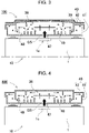
- Third cover 39 includes a structure that relaxes a load near a fastening part of bolt 29. Specifically, as shown in the schematic sectional view of Fig.
- third cover 39 includes fastening body 39a in a plate shape, intermediate part 39b in which both ends of fastening body 39a are bent, and coupling piece 39c that is provided with a height difference from fastening body 39a by bending an end of intermediate part 39b far from fastening body 39a.
- Fastening body 39a and coupling piece 39c are formed in a stepped shape via intermediate part 39b.
- Coupling piece 39c forms fastening screw hole 39d.
- Fig. 8 is an exploded perspective view with an enlarged view of a main part showing a state in which reinforcement cover 60 is removed from cover assembly 40 of Fig. 2
- Fig. 9 is an exploded perspective view of Fig. 8
- Fig. 10 is an exploded perspective view of Fig. 9 as viewed obliquely from below
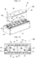
- Fig. 11 is an exploded perspective view showing a state in which reinforcement cover 60 is removed from power source device 100 of Fig. 1
- Fig. 12 is a plan view of power source device 100 of Fig. 1 with reinforcement cover 60 in a transparent state
- Fig. 8 is an exploded perspective view with an enlarged view of a main part showing a state in which reinforcement cover 60 is removed from cover assembly 40 of Fig. 2
- Fig. 9 is an exploded perspective view of Fig. 8
- Fig. 10 is an exploded perspective view of Fig. 9 as viewed obliquely from below
- Fig. 11 is an exploded perspective view showing a state in which reinforcement cover 60
- Cover assembly 40 shown in these figures includes lower cover 46, upper cover 50, and reinforcement cover 60.
- the lower cover corresponds to first cover 41 described above
- upper cover 50 corresponds to second cover 42
- reinforcement cover 60 corresponds to third cover 39.
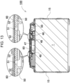
- Lower cover 46 is provided on the upper surface of battery stack 10, and defines first gas duct 43 communicating with gas discharge valve 1c. As shown in Figs. 9 and 10 , lower cover 46 has gas introduction port 47 opened at a position corresponding to gas discharge valve 1c of battery cell 1. As shown in Figs. 9 , 10 , 13 , and the like, lower cover 46 has a large number of baffle plates 48, and by baffle plates 48 changing the travelling direction until the high-temperature, high-pressure gas is discharged, the momentum is reduced and the temperature is lowered. The gas discharge path is provided not only in the stack direction of battery cells 1 but also in a direction intersecting the stack direction. Lower cover 46 is made of resin having excellent insulation properties, for example, polycarbonate.
- intermediate plate 49 is provided at the center in the width of battery stack 10, and is disposed so as to oppose gas discharge valve 1c.
- Intermediate plate 49 is made of a material excellent in strength, for example, metal. Due to this, even if a high-temperature, high-pressure gas is discharged from the gas discharge path, the gas is received by metallic intermediate plate 49 higher in strength than the resin cover, so that a situation in which the gas is directly ejected through power source device 100 is avoided.
- Upper cover 50 is provided on the upper surface of lower cover 46, and defines second gas duct 44 on the upper surface of first gas duct 43.
- Upper cover 50 is made of resin.
- a plurality of communication holes 51 through which first gas duct 43 and second gas duct 44 communicate with each other are formed on the upper surface of upper cover 50.
- communication holes 51 are not opened corresponding to all the battery cells, but are discretely opened so as to serve the plurality of battery cells.
- communication holes 51 are opened at three places in the stack direction with respect to battery stack 10 in which 12 battery cells 1 are stacked.
- communication holes 51 are provided not at positions opposed to gas discharge valve 1c but at positions offset from gas discharge valve 1c. By not directly opening communication holes 51 with respect to gas discharge valve 1c, it is possible to easily disperse the gas.
- Gas discharge valve 1c is provided at the center of sealing plate 1b of battery cell 1 in the example shown in Fig. 2 .
- communication holes 51 are opened at positions corresponding to the right and left of sealing plate 1b of battery cell 1.
- Communication hole 51 is preferably formed in a slit shape.
- the path area of second gas duct 44 can be set by adjusting the width and length of the slit, the height of second gas duct 44, and the like, and the amount of gas to be discharged can be controlled.
- the height of second gas duct 44 is defined by the height of communication rib 52 described later.
- Upper cover 50 is provided with communication rib 52 protruding toward reinforcement cover 60 around communication hole 51. This makes it possible to block a situation in which the path for introducing gas into second gas duct 44 is obstructed.
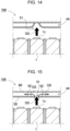
- a configuration provided with no communication rib as in power source device 700 shown in the schematic sectional view of Fig. 14 , it is conceivable that when high pressure gas is discharged from gas discharge valve 1c, the periphery of communication hole 51 opened on upper cover 50 is deformed by the pressure of the gas, and the gas discharge path is closed. In this state, the gas is not guided to second gas duct 44, and the gas cannot be dispersed and discharged through second gas duct 44.
- the schematic sectional view of Fig. 15 by providing communication rib 52 around communication hole 51, it becomes possible to block deformation around communication hole 51, secure an opening end to second gas duct 44, and guide the high-pressure gas to second gas duct 44.
- Communication rib 52 is provided on not the entirety but a part of circumference of communication hole 51 so as not to block inflow of the gas into second gas duct 44. It is preferable that as shown in the plan view of Fig. 12 , a pair of communication ribs 52 are provided so as to oppose both sides of communication hole 51. In a case of communication hole 51 in a slit shape, it is preferable to arrange the pair of communication ribs 52 so as to intersect with the long direction of the slit. In this example, communication rib 52 is integrally molded with resin upper cover 50. This configuration makes it possible to position and easily form communication rib 52 around communication hole 51. However, it is needless to say that the communication rib may be provided near the reinforcement cover side. In particular, by protruding the communication rib on the metallic reinforcement cover by punching or the like, it is possible to form a communication rib that is stronger and hardly deformed.
- upper cover 50 is provided with rib for partition 53 that partitions between the plurality of communication holes 51 adjacent to each other. This makes it possible to partition second gas duct 44 for each communication hole 51, and to cause the high-pressure gas introduced into second gas duct 44 from communication hole 51 not to be discharged in a concentrated manner at one place.
- battery stack 10 in which 12 battery cells 1 are stacked is partitioned into three for every four cells, and further divided into two sections on the right and left of battery cell 1, so that battery stack 10 is divided into a total of six partitions.
- the partition rib protrudes on the upper surface of upper cover 50, but the present invention is not limited to this configuration, and it goes without saying that the partition rib may protrude from the reinforcement cover, for example.
- the gas discharge path is preferably provided not only in the stack direction of battery cells 1 but also in a direction intersecting the stack direction. By discharging the gas also in the intersecting direction in this manner, it is possible to efficiently discharge the gas to the outside of the power source device and enhance safety.
- a gas discharge path is formed in each of first gas duct 43 and second gas duct 44 so that gas is discharged also in the up-down direction in the figure.
- Reinforcement cover 60 is provided on the upper surface of upper cover 50.
- Second gas duct 44 is formed between reinforcement cover 60 and upper cover 50.
- Reinforcement cover 60 abuts on the upper surface of upper cover 50 via communication rib 52.
- Reinforcement cover 60 may form bead 61 in order to increase rigidity.
- bead 61 is formed at the center in the long direction of reinforcement cover 60. The strength can be improved by simple processing of forming bead 61 on metal sheet reinforcement cover 60 in this manner.
- the power source device includes total terminal strip 70 that draws a total output of the plurality of battery cells 1 connected in series and in parallel via the bus bar.
- Total terminal strip 70 is made of a metal sheet excellent in conductivity.
- reinforcement cover 60 forms exposure part 62 that exposes total terminal strip 70. This makes it possible to secure the insulating distance by separating, while using, metallic reinforcement cover 60 from total terminal strips 70 also made of metal, and possible to avoid the possibility of occurrence of an unintended short circuit.
- Exposure part 62 can be an exposed cutout in which corner parts of reinforcement cover 60 are cut out so as to expose total terminal strip 70 as shown in Fig. 9 and the like. This enhances the safety by separating metallic reinforcement cover 60 and total terminal strip 70 in the horizontal plane so as not to overlap each other.
- exposure part 62 may be an exposure window that exposes the total terminal strip.
- total terminal strip 70 is provided near one side surface (lower side in the figure) of the upper surface of end plate 20.
- Exposure part 62 may be formed only at the lower corner of the end of reinforcement cover 60 accordingly, or may be provided on both sides of the end as shown in Fig. 11 and the like. This makes it possible to attach reinforcement cover 60 even if the reinforcement cover is turned in the right-left direction, and the assembling workability is improved.
- Reinforcement cover 60 is fixed to the upper surface of end plate 20 with bolt 29 or the like as shown in Fig. 10 .
- Reinforcement cover 60 includes a structure that relaxes a load near a fastening part of bolt 29.
- reinforcement cover 60 is bent at two places of first bent part BT1 and second bent part BT2 by protruding an intermediate part of fastening body 39a formed with exposure part 62, and thus forms intermediate part 39b and coupling piece 39c.
- First bent part BT1 and second bent part BT2 are bent so as to be parallel to each other. The bending direction is set such that fastening body 39a and coupling piece 39c are parallel with different heights.
- first bent part BT1' and second bent part BT2' become not in an L shape but a curved surface as shown in Fig. 17 , it is possible to further enhance the load distribution effect, and to control the load generated by the swelling force of the battery stack and the like.
- coupling piece 39c is formed to be narrower in width than the fastening main surface, so that a section modulus is reduced, and an influence of swelling and contraction of battery stack 10 is reduced.
- width W1 of reinforcement cover 60 is reduced to W2 in coupling piece 39c by forming both side corners of the reinforcement cover end so as to be gouged by the exposure part.
- Power source device 100 described above can be used as a power source for a vehicle that supplies electric power to a motor that causes an electric vehicle to travel.
- electric vehicles such as a hybrid vehicle and a plug-in hybrid vehicle that travel with both an engine and a motor, or an electric car that travels only with a motor can be used, and the power source device is used as a power source for these vehicles.
- An example will be described in which a large-capacity, high-output power source device where a large number of power source devices 100 described above are connected in series or in parallel in order to obtain electric power for driving an electric vehicle and a necessary controlling circuit is further added is constructed.
- Fig. 18 shows an example in which power source device 100 is equipped on a hybrid vehicle that travels with both an engine and a motor.
- Vehicle HV equipped with power source device 100 shown in this figure includes vehicle body 91, engine 96 and motor for travelling 93 that cause vehicle body 91 to travel, wheels 97 driven by engine 96 and motor for travelling 93, power source device 100 that supplies electric power to motor 93, and generator 94 that charges the battery of power source device 100.
- Power source device 100 is connected to motor 93 and generator 94 via DC/AC inverter 95. Vehicle HV travels with both motor 93 and engine 96 while charging and discharging the battery of power source device 100.
- Motor 93 is driven in a region where engine efficiency is low, for example, during acceleration or low-speed travelling, and causes the vehicle to travel. Motor 93 is driven by electric power supplied from power source device 100. Generator 94 is driven by engine 96 or regenerative braking when the vehicle is braked, to charge the battery of power source device 100. As shown in Fig. 18 , vehicle HV may include charging plug 98 for charging power source device 100. By connecting charging plug 98 to an external power source, it is possible to charge power source device 100.
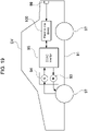
- Fig. 19 shows an example in which power source device 100 is equipped on an electric car that travels only with a motor.
- Vehicle EV equipped with power source device 100 shown in this figure includes vehicle body 91, motor for travelling 93 that causes vehicle body 91 to travel, wheels 97 that are driven by motor 93, power source device 100 that supplies electric power to motor 93, and generator 94 that charges the battery of power source device 100.
- Power source device 100 is connected to motor 93 and generator 94 via DC/AC inverter 95.
- Motor 93 is driven by electric power supplied from power source device 100.
- Generator 94 is driven by the energy at the time of applying regenerative braking to vehicle EV, and charges the battery of power source device 100.
- Vehicle EV includes charging plug 98, and power source device 100 can be charged by connecting charging plug 98 to an external power source.
- the present invention does not limit the application of the power source device to a power source for a motor that causes a vehicle to travel.
- the power source device according to the exemplary embodiment can be used as a power supply for a power storage device that stores electricity by charging a battery with electric power generated by photovoltaic power generation, wind power generation, or other methods.
- Fig. 20 shows an electrical storage device that stores electricity by charging the battery of power source device 100 with solar battery 82.
- the electrical storage device shown in Fig. 20 charges the batteries of power source device 100 with electric power generated by solar battery 82 that is disposed on a roof or a rooftop of building 81 such as a house or a factory.
- the power storage device charges the batteries of power source device 100 through charging circuit 83 with solar battery 82 serving as a charging power supply, and then supplies electric power to load 86 via DC/AC inverter 85.
- this electrical storage device includes a charge mode and a discharge mode.
- DC/AC inverter 85 and charging circuit 83 are connected to power source device 100 via discharging switch 87 and charging switch 84, respectively. On/off of discharging switch 87 and charging switch 84 is switched by power supply controller 88 of the electrical storage device.
- power supply controller 88 turns on charging switch 84 and turns off discharging switch 87 to allow charging from charging circuit 83 to power source device 100.
- power supply controller 88 turns off charging switch 84 and turns on discharging switch 87 to switch the mode to the discharge mode and allows discharging from power source device 100 to load 86.
- supply of electric power to load 86 and charging of power source device 100 can be simultaneously carried out by turning on charging switch 84 and turning on discharging switch 87.
- the power source device can also be used as a power source for an electrical storage device that stores electricity by charging a battery using midnight electric power at night.
- the power source device that is charged with midnight electric power is charged with the midnight electric power that is surplus electric power generated by a power station, and outputs the electric power during the daytime when an electric power load increases, which can limit peak electric power during the daytime to a small value.
- the power source device can also be used as a power source charged with both output of a solar battery and the midnight electric power. Effectively using both electric power generated by the solar battery and the midnight electric power, this power source device can efficiently perform power storage in consideration of weather and electric power consumption.
- the power storage system as described above can be suitably used in applications including a backup power source device that can be equipped on a computer server rack, a backup power source device for wireless base stations for cellular phones and the like, an electrical storage device combined with a solar battery such as a power storage power source for homes and factories or a power source for street lights, and a backup power source for traffic lights and traffic indicators on roads.
- a backup power source device that can be equipped on a computer server rack
- a backup power source device for wireless base stations for cellular phones and the like an electrical storage device combined with a solar battery such as a power storage power source for homes and factories or a power source for street lights
- a backup power source for traffic lights and traffic indicators on roads including a backup power source device that can be equipped on a computer server rack, a backup power source device for wireless base stations for cellular phones and the like, an electrical storage device combined with a solar battery such as a power storage power source for homes and factories or a power source for street lights, and a backup power source for traffic lights
- the power source device can be suitably used as a large current power supply used for a power source of a motor that drives electric vehicles such as a hybrid vehicle, a fuel cell vehicle, an electric car, or an electric motorcycle.
- Examples include a power source device for a plug-in hybrid electric car and a hybrid electric car that can switch between an EV travelling mode and an HEV travelling mode, an electric car, and the like.
- the power source device can also be appropriately used for applications including a backup power source device that can be equipped on a computer sever rack, a backup power source device for wireless base stations of cellular phones and the like, an electrical storage device combined with a solar battery such as a power storage power source for homes and for factories and a power source for street lights, and a backup power source for traffic lights.
Landscapes
- Chemical & Material Sciences (AREA)
- Chemical Kinetics & Catalysis (AREA)
- Electrochemistry (AREA)
- General Chemical & Material Sciences (AREA)
- Engineering & Computer Science (AREA)
- Manufacturing & Machinery (AREA)
- Battery Mounting, Suspending (AREA)
- Gas Exhaust Devices For Batteries (AREA)
Applications Claiming Priority (2)
| Application Number | Priority Date | Filing Date | Title |
|---|---|---|---|
| JP2020064067 | 2020-03-31 | ||
| PCT/JP2021/001788 WO2021199596A1 (ja) | 2020-03-31 | 2021-01-20 | 電源装置及びこれを備える車両並びに蓄電装置 |
Publications (2)
| Publication Number | Publication Date |
|---|---|
| EP4131564A1 true EP4131564A1 (de) | 2023-02-08 |
| EP4131564A4 EP4131564A4 (de) | 2024-07-03 |
Family
ID=77929809
Family Applications (1)
| Application Number | Title | Priority Date | Filing Date |
|---|---|---|---|
| EP21779229.0A Pending EP4131564A4 (de) | 2020-03-31 | 2021-01-20 | Stromquellenvorrichtung und fahrzeug sowie energiespeichervorrichtung damit |
Country Status (5)
| Country | Link |
|---|---|
| US (1) | US12500302B2 (de) |
| EP (1) | EP4131564A4 (de) |
| JP (1) | JP7662614B2 (de) |
| CN (1) | CN115004466B (de) |
| WO (1) | WO2021199596A1 (de) |
Cited By (1)
| Publication number | Priority date | Publication date | Assignee | Title |
|---|---|---|---|---|
| EP4386941A1 (de) * | 2022-12-15 | 2024-06-19 | AESC Japan Ltd. | Batteriepack |
Families Citing this family (1)
| Publication number | Priority date | Publication date | Assignee | Title |
|---|---|---|---|---|
| KR102925886B1 (ko) * | 2021-07-07 | 2026-02-10 | 주식회사 엘지에너지솔루션 | 쿨링 핀들이 합치된 팩 케이스를 구비한 배터리 팩 |
Family Cites Families (12)
| Publication number | Priority date | Publication date | Assignee | Title |
|---|---|---|---|---|
| JP2012160347A (ja) * | 2011-01-31 | 2012-08-23 | Sanyo Electric Co Ltd | 電源装置及び電源装置を備える車両 |
| JP6136230B2 (ja) | 2012-01-16 | 2017-05-31 | 株式会社Gsユアサ | 組電池及び電源装置 |
| KR101419019B1 (ko) * | 2012-09-28 | 2014-07-11 | 신경민 | 플라스틱 스텐트 삽입장치 |
| JP5998868B2 (ja) | 2012-11-15 | 2016-09-28 | 株式会社豊田自動織機 | 蓄電装置モジュール |
| JP2014220149A (ja) * | 2013-05-09 | 2014-11-20 | 愛三工業株式会社 | バスバーモジュール |
| JP6174381B2 (ja) * | 2013-06-06 | 2017-08-02 | 日立オートモティブシステムズ株式会社 | 蓄電ブロックおよび蓄電モジュール |
| JP6574987B2 (ja) | 2015-02-25 | 2019-09-18 | パナソニックIpマネジメント株式会社 | 電池モジュール |
| JP6724300B2 (ja) | 2015-06-29 | 2020-07-15 | 株式会社Gsユアサ | 蓄電装置 |
| JP6613773B2 (ja) * | 2015-09-30 | 2019-12-04 | 株式会社Gsユアサ | 蓄電装置 |
| JP7138308B2 (ja) | 2018-03-12 | 2022-09-16 | パナソニックIpマネジメント株式会社 | 電池パック用排気ダクトおよび電池パック |
| EP3806182A4 (de) * | 2018-06-05 | 2021-07-07 | SANYO Electric Co., Ltd. | Batteriemodul und damit ausgestattetes fahrzeug |
| JP7225257B2 (ja) * | 2018-09-20 | 2023-02-20 | 三洋電機株式会社 | 電源装置及び電源装置を備える車両並びに蓄電装置 |
-
2021
- 2021-01-20 JP JP2022511564A patent/JP7662614B2/ja active Active
- 2021-01-20 WO PCT/JP2021/001788 patent/WO2021199596A1/ja not_active Ceased
- 2021-01-20 EP EP21779229.0A patent/EP4131564A4/de active Pending
- 2021-01-20 CN CN202180011266.4A patent/CN115004466B/zh active Active
- 2021-01-20 US US17/906,882 patent/US12500302B2/en active Active
Cited By (1)
| Publication number | Priority date | Publication date | Assignee | Title |
|---|---|---|---|---|
| EP4386941A1 (de) * | 2022-12-15 | 2024-06-19 | AESC Japan Ltd. | Batteriepack |
Also Published As
| Publication number | Publication date |
|---|---|
| CN115004466A (zh) | 2022-09-02 |
| US12500302B2 (en) | 2025-12-16 |
| CN115004466B (zh) | 2024-08-23 |
| JP7662614B2 (ja) | 2025-04-15 |
| JPWO2021199596A1 (de) | 2021-10-07 |
| EP4131564A4 (de) | 2024-07-03 |
| WO2021199596A1 (ja) | 2021-10-07 |
| US20230246274A1 (en) | 2023-08-03 |
Similar Documents
| Publication | Publication Date | Title |
|---|---|---|
| EP4131612B1 (de) | Stromversorgungsvorrichtung sowie fahrzeug und stromspeichervorrichtung damit | |
| US11660951B2 (en) | Power supply device, vehicle equipped with same, and electricity storage device | |
| US11990636B2 (en) | Power supply device, electric vehicle using same, and power storage device | |
| US12237532B2 (en) | Power supply device, and vehicle and electrical storage device each equipped with same | |
| US11817593B2 (en) | Power supply device and vehicle provided with power supply device | |
| JP7491939B2 (ja) | 電池、電気機器、電池の製造方法及び装置 | |
| EP4131561A1 (de) | Stromversorgungsvorrichtung, fahrzeug damit und energiespeichervorrichtung | |
| EP3855526B1 (de) | Stromversorgungsvorrichtung, mit stromversorgungsvorrichtung ausgerüstetes fahrzeug und stromspeichervorrichtung | |
| EP4012820B1 (de) | Stromversorgungsvorrichtung, elektrofahrzeug mit verwendung davon und stromspeichervorrichtung | |
| CN115053386B (zh) | 电源装置和具备该电源装置的车辆以及蓄电装置 | |
| US12531306B2 (en) | Power supply device, electric vehicle using same, and power storage device | |
| EP3951910A1 (de) | Stromversorgungsvorrichtung, elektrisches fahrzeug und energiespeichervorrichtung damit, befestigungsglied für eine stromversorgungseinrichtung, verfahren zur herstellung einer stromversorgungseinrichtung und verfahren zur herstellung eines befestigungsgliedes für eine stromversorgungseinrichtung | |
| US12315948B2 (en) | Power supply device and vehicle and power storage device having same | |
| US12500302B2 (en) | Power source device, and vehicle and power storage device each equipped with same | |
| JP7532066B2 (ja) | 電源装置及びこれを備える車両並びに蓄電装置 | |
| CN223245871U (zh) | 电池单体、电池装置、用电装置及储能装置 |
Legal Events
| Date | Code | Title | Description |
|---|---|---|---|
| STAA | Information on the status of an ep patent application or granted ep patent |
Free format text: STATUS: THE INTERNATIONAL PUBLICATION HAS BEEN MADE |
|
| PUAI | Public reference made under article 153(3) epc to a published international application that has entered the european phase |
Free format text: ORIGINAL CODE: 0009012 |
|
| STAA | Information on the status of an ep patent application or granted ep patent |
Free format text: STATUS: REQUEST FOR EXAMINATION WAS MADE |
|
| 17P | Request for examination filed |
Effective date: 20221011 |
|
| AK | Designated contracting states |
Kind code of ref document: A1 Designated state(s): AL AT BE BG CH CY CZ DE DK EE ES FI FR GB GR HR HU IE IS IT LI LT LU LV MC MK MT NL NO PL PT RO RS SE SI SK SM TR |
|
| DAV | Request for validation of the european patent (deleted) | ||
| DAX | Request for extension of the european patent (deleted) | ||
| A4 | Supplementary search report drawn up and despatched |
Effective date: 20240531 |
|
| RIC1 | Information provided on ipc code assigned before grant |
Ipc: H01M 50/543 20210101ALI20240524BHEP Ipc: H01M 50/50 20210101ALI20240524BHEP Ipc: H01M 50/342 20210101ALI20240524BHEP Ipc: H01M 50/20 20210101ALI20240524BHEP Ipc: H01M 10/44 20060101AFI20240524BHEP |