EP4131607A1 - Batteriepack und fahrzeug - Google Patents
Batteriepack und fahrzeug Download PDFInfo
- Publication number
- EP4131607A1 EP4131607A1 EP21814471.5A EP21814471A EP4131607A1 EP 4131607 A1 EP4131607 A1 EP 4131607A1 EP 21814471 A EP21814471 A EP 21814471A EP 4131607 A1 EP4131607 A1 EP 4131607A1
- Authority
- EP
- European Patent Office
- Prior art keywords
- battery pack
- electrical connector
- battery
- hole
- batteries
- Prior art date
- Legal status (The legal status is an assumption and is not a legal conclusion. Google has not performed a legal analysis and makes no representation as to the accuracy of the status listed.)
- Pending
Links
Images

Classifications
-
- H—ELECTRICITY
- H01—ELECTRIC ELEMENTS
- H01M—PROCESSES OR MEANS, e.g. BATTERIES, FOR THE DIRECT CONVERSION OF CHEMICAL ENERGY INTO ELECTRICAL ENERGY
- H01M50/00—Constructional details or processes of manufacture of the non-active parts of electrochemical cells other than fuel cells, e.g. hybrid cells
- H01M50/50—Current conducting connections for cells or batteries
- H01M50/502—Interconnectors for connecting terminals of adjacent batteries; Interconnectors for connecting cells outside a battery casing
- H01M50/507—Interconnectors for connecting terminals of adjacent batteries; Interconnectors for connecting cells outside a battery casing comprising an arrangement of two or more busbars within a container structure, e.g. busbar modules
-
- H—ELECTRICITY
- H01—ELECTRIC ELEMENTS
- H01M—PROCESSES OR MEANS, e.g. BATTERIES, FOR THE DIRECT CONVERSION OF CHEMICAL ENERGY INTO ELECTRICAL ENERGY
- H01M50/00—Constructional details or processes of manufacture of the non-active parts of electrochemical cells other than fuel cells, e.g. hybrid cells
- H01M50/20—Mountings; Secondary casings or frames; Racks, modules or packs; Suspension devices; Shock absorbers; Transport or carrying devices; Holders
- H01M50/296—Mountings; Secondary casings or frames; Racks, modules or packs; Suspension devices; Shock absorbers; Transport or carrying devices; Holders characterised by terminals of battery packs
-
- B—PERFORMING OPERATIONS; TRANSPORTING
- B60—VEHICLES IN GENERAL
- B60L—PROPULSION OF ELECTRICALLY-PROPELLED VEHICLES; SUPPLYING ELECTRIC POWER FOR AUXILIARY EQUIPMENT OF ELECTRICALLY-PROPELLED VEHICLES; ELECTRODYNAMIC BRAKE SYSTEMS FOR VEHICLES IN GENERAL; MAGNETIC SUSPENSION OR LEVITATION FOR VEHICLES; MONITORING OPERATING VARIABLES OF ELECTRICALLY-PROPELLED VEHICLES; ELECTRIC SAFETY DEVICES FOR ELECTRICALLY-PROPELLED VEHICLES
- B60L50/00—Electric propulsion with power supplied within the vehicle
- B60L50/50—Electric propulsion with power supplied within the vehicle using propulsion power supplied by batteries or fuel cells
- B60L50/60—Electric propulsion with power supplied within the vehicle using propulsion power supplied by batteries or fuel cells using power supplied by batteries
- B60L50/64—Constructional details of batteries specially adapted for electric vehicles
-
- B—PERFORMING OPERATIONS; TRANSPORTING
- B60—VEHICLES IN GENERAL
- B60L—PROPULSION OF ELECTRICALLY-PROPELLED VEHICLES; SUPPLYING ELECTRIC POWER FOR AUXILIARY EQUIPMENT OF ELECTRICALLY-PROPELLED VEHICLES; ELECTRODYNAMIC BRAKE SYSTEMS FOR VEHICLES IN GENERAL; MAGNETIC SUSPENSION OR LEVITATION FOR VEHICLES; MONITORING OPERATING VARIABLES OF ELECTRICALLY-PROPELLED VEHICLES; ELECTRIC SAFETY DEVICES FOR ELECTRICALLY-PROPELLED VEHICLES
- B60L58/00—Methods or circuit arrangements for monitoring or controlling batteries or fuel cells, specially adapted for electric vehicles
- B60L58/10—Methods or circuit arrangements for monitoring or controlling batteries or fuel cells, specially adapted for electric vehicles for monitoring or controlling batteries
- B60L58/24—Methods or circuit arrangements for monitoring or controlling batteries or fuel cells, specially adapted for electric vehicles for monitoring or controlling batteries for controlling the temperature of batteries
- B60L58/26—Methods or circuit arrangements for monitoring or controlling batteries or fuel cells, specially adapted for electric vehicles for monitoring or controlling batteries for controlling the temperature of batteries by cooling
-
- H—ELECTRICITY
- H01—ELECTRIC ELEMENTS
- H01M—PROCESSES OR MEANS, e.g. BATTERIES, FOR THE DIRECT CONVERSION OF CHEMICAL ENERGY INTO ELECTRICAL ENERGY
- H01M10/00—Secondary cells; Manufacture thereof
- H01M10/60—Heating or cooling; Temperature control
- H01M10/61—Types of temperature control
- H01M10/613—Cooling or keeping cold
-
- H—ELECTRICITY
- H01—ELECTRIC ELEMENTS
- H01M—PROCESSES OR MEANS, e.g. BATTERIES, FOR THE DIRECT CONVERSION OF CHEMICAL ENERGY INTO ELECTRICAL ENERGY
- H01M10/00—Secondary cells; Manufacture thereof
- H01M10/60—Heating or cooling; Temperature control
- H01M10/62—Heating or cooling; Temperature control specially adapted for specific applications
- H01M10/625—Vehicles
-
- H—ELECTRICITY
- H01—ELECTRIC ELEMENTS
- H01M—PROCESSES OR MEANS, e.g. BATTERIES, FOR THE DIRECT CONVERSION OF CHEMICAL ENERGY INTO ELECTRICAL ENERGY
- H01M10/00—Secondary cells; Manufacture thereof
- H01M10/60—Heating or cooling; Temperature control
- H01M10/64—Heating or cooling; Temperature control characterised by the shape of the cells
- H01M10/647—Prismatic or flat cells, e.g. pouch cells
-
- H—ELECTRICITY
- H01—ELECTRIC ELEMENTS
- H01M—PROCESSES OR MEANS, e.g. BATTERIES, FOR THE DIRECT CONVERSION OF CHEMICAL ENERGY INTO ELECTRICAL ENERGY
- H01M10/00—Secondary cells; Manufacture thereof
- H01M10/60—Heating or cooling; Temperature control
- H01M10/65—Means for temperature control structurally associated with the cells
- H01M10/653—Means for temperature control structurally associated with the cells characterised by electrically insulating or thermally conductive materials
-
- H—ELECTRICITY
- H01—ELECTRIC ELEMENTS
- H01M—PROCESSES OR MEANS, e.g. BATTERIES, FOR THE DIRECT CONVERSION OF CHEMICAL ENERGY INTO ELECTRICAL ENERGY
- H01M10/00—Secondary cells; Manufacture thereof
- H01M10/60—Heating or cooling; Temperature control
- H01M10/65—Means for temperature control structurally associated with the cells
- H01M10/655—Solid structures for heat exchange or heat conduction
- H01M10/6554—Rods or plates
-
- H—ELECTRICITY
- H01—ELECTRIC ELEMENTS
- H01M—PROCESSES OR MEANS, e.g. BATTERIES, FOR THE DIRECT CONVERSION OF CHEMICAL ENERGY INTO ELECTRICAL ENERGY
- H01M10/00—Secondary cells; Manufacture thereof
- H01M10/60—Heating or cooling; Temperature control
- H01M10/65—Means for temperature control structurally associated with the cells
- H01M10/655—Solid structures for heat exchange or heat conduction
- H01M10/6556—Solid parts with flow channel passages or pipes for heat exchange
-
- H—ELECTRICITY
- H01—ELECTRIC ELEMENTS
- H01M—PROCESSES OR MEANS, e.g. BATTERIES, FOR THE DIRECT CONVERSION OF CHEMICAL ENERGY INTO ELECTRICAL ENERGY
- H01M10/00—Secondary cells; Manufacture thereof
- H01M10/60—Heating or cooling; Temperature control
- H01M10/65—Means for temperature control structurally associated with the cells
- H01M10/656—Means for temperature control structurally associated with the cells characterised by the type of heat-exchange fluid
- H01M10/6561—Gases
-
- H—ELECTRICITY
- H01—ELECTRIC ELEMENTS
- H01M—PROCESSES OR MEANS, e.g. BATTERIES, FOR THE DIRECT CONVERSION OF CHEMICAL ENERGY INTO ELECTRICAL ENERGY
- H01M10/00—Secondary cells; Manufacture thereof
- H01M10/60—Heating or cooling; Temperature control
- H01M10/65—Means for temperature control structurally associated with the cells
- H01M10/656—Means for temperature control structurally associated with the cells characterised by the type of heat-exchange fluid
- H01M10/6567—Liquids
- H01M10/6568—Liquids characterised by flow circuits, e.g. loops, located externally to the cells or cell casings
-
- H—ELECTRICITY
- H01—ELECTRIC ELEMENTS
- H01M—PROCESSES OR MEANS, e.g. BATTERIES, FOR THE DIRECT CONVERSION OF CHEMICAL ENERGY INTO ELECTRICAL ENERGY
- H01M50/00—Constructional details or processes of manufacture of the non-active parts of electrochemical cells other than fuel cells, e.g. hybrid cells
- H01M50/20—Mountings; Secondary casings or frames; Racks, modules or packs; Suspension devices; Shock absorbers; Transport or carrying devices; Holders
- H01M50/204—Racks, modules or packs for multiple batteries or multiple cells
- H01M50/207—Racks, modules or packs for multiple batteries or multiple cells characterised by their shape
- H01M50/209—Racks, modules or packs for multiple batteries or multiple cells characterised by their shape adapted for prismatic or rectangular cells
-
- H—ELECTRICITY
- H01—ELECTRIC ELEMENTS
- H01M—PROCESSES OR MEANS, e.g. BATTERIES, FOR THE DIRECT CONVERSION OF CHEMICAL ENERGY INTO ELECTRICAL ENERGY
- H01M50/00—Constructional details or processes of manufacture of the non-active parts of electrochemical cells other than fuel cells, e.g. hybrid cells
- H01M50/20—Mountings; Secondary casings or frames; Racks, modules or packs; Suspension devices; Shock absorbers; Transport or carrying devices; Holders
- H01M50/244—Secondary casings; Racks; Suspension devices; Carrying devices; Holders characterised by their mounting method
-
- H—ELECTRICITY
- H01—ELECTRIC ELEMENTS
- H01M—PROCESSES OR MEANS, e.g. BATTERIES, FOR THE DIRECT CONVERSION OF CHEMICAL ENERGY INTO ELECTRICAL ENERGY
- H01M50/00—Constructional details or processes of manufacture of the non-active parts of electrochemical cells other than fuel cells, e.g. hybrid cells
- H01M50/20—Mountings; Secondary casings or frames; Racks, modules or packs; Suspension devices; Shock absorbers; Transport or carrying devices; Holders
- H01M50/249—Mountings; Secondary casings or frames; Racks, modules or packs; Suspension devices; Shock absorbers; Transport or carrying devices; Holders specially adapted for aircraft or vehicles, e.g. cars or trains
-
- H—ELECTRICITY
- H01—ELECTRIC ELEMENTS
- H01M—PROCESSES OR MEANS, e.g. BATTERIES, FOR THE DIRECT CONVERSION OF CHEMICAL ENERGY INTO ELECTRICAL ENERGY
- H01M50/00—Constructional details or processes of manufacture of the non-active parts of electrochemical cells other than fuel cells, e.g. hybrid cells
- H01M50/20—Mountings; Secondary casings or frames; Racks, modules or packs; Suspension devices; Shock absorbers; Transport or carrying devices; Holders
- H01M50/262—Mountings; Secondary casings or frames; Racks, modules or packs; Suspension devices; Shock absorbers; Transport or carrying devices; Holders with fastening means, e.g. locks
-
- H—ELECTRICITY
- H01—ELECTRIC ELEMENTS
- H01M—PROCESSES OR MEANS, e.g. BATTERIES, FOR THE DIRECT CONVERSION OF CHEMICAL ENERGY INTO ELECTRICAL ENERGY
- H01M50/00—Constructional details or processes of manufacture of the non-active parts of electrochemical cells other than fuel cells, e.g. hybrid cells
- H01M50/20—Mountings; Secondary casings or frames; Racks, modules or packs; Suspension devices; Shock absorbers; Transport or carrying devices; Holders
- H01M50/271—Lids or covers for the racks or secondary casings
-
- H—ELECTRICITY
- H01—ELECTRIC ELEMENTS
- H01M—PROCESSES OR MEANS, e.g. BATTERIES, FOR THE DIRECT CONVERSION OF CHEMICAL ENERGY INTO ELECTRICAL ENERGY
- H01M2220/00—Batteries for particular applications
- H01M2220/20—Batteries in motive systems, e.g. vehicle, ship, plane
-
- Y—GENERAL TAGGING OF NEW TECHNOLOGICAL DEVELOPMENTS; GENERAL TAGGING OF CROSS-SECTIONAL TECHNOLOGIES SPANNING OVER SEVERAL SECTIONS OF THE IPC; TECHNICAL SUBJECTS COVERED BY FORMER USPC CROSS-REFERENCE ART COLLECTIONS [XRACs] AND DIGESTS
- Y02—TECHNOLOGIES OR APPLICATIONS FOR MITIGATION OR ADAPTATION AGAINST CLIMATE CHANGE
- Y02E—REDUCTION OF GREENHOUSE GAS [GHG] EMISSIONS, RELATED TO ENERGY GENERATION, TRANSMISSION OR DISTRIBUTION
- Y02E60/00—Enabling technologies; Technologies with a potential or indirect contribution to GHG emissions mitigation
- Y02E60/10—Energy storage using batteries
Definitions
- the present disclosure relates to the technical field of batteries, and specifically to a battery pack and a vehicle.
- the battery pack for new energy vehicles is assembled by arranging several batteries in sequence to form a battery array, then welding the electrode terminals of the batteries to an electrical connector to enable electrical connection between batteries, and then positioning the welded battery array in a tray.
- the welded battery array as a whole is difficult to be mounted in the tray, and problems such as falling off of the welded portion between the electrode terminals and the electrical connector and damage to the electrical connector are likely to occur in the process of transferring the battery array into the tray, thereby increasing the production cost and influencing the production and use of the battery pack.
- an object of the present disclosure is to provide a battery pack, which can simplify the connection process of an electrode terminal of a battery to an electrical connector, thereby optimizing the process flow
- the present disclosure further provides a vehicle.
- the battery pack according to the present disclosure includes a tray, provided with an accommodating groove thereon, where at least one through hole is provided on a side wall of the accommodating groove; at least one battery array, arranged in the accommodating groove, and each including multiple batteries arranged in sequence, where each of the batteries includes an electrode terminal at the side facing the through hole; at least one electrical connector, provided in the accommodating groove and connected to the electrode terminals of at least two batteries, where the through hole allows the electrode terminals and the electrical connector to be exposed.
- the electrode terminals of the batteries and the electrical connector in the accommodating groove can be connected via the through hole. This eliminates the need of performing the connection procedure of the electrode terminals of the batteries to the electrical connector outside the tray, thereby simplifying the assembly process of the battery pack, and optimizing the process flow.
- the tray includes a bottom plate and side beams peripherally arranged around the bottom plate, where the bottom plate and the side beams jointly define the accommodating groove.
- the side beams include a first side beam and a second side beam which are oppositely arranged along a first direction. At least one of the first side beam and the second side beam is provided with the through hole, and the first direction is a length direction of the battery pack or a width direction of the battery pack.
- At least two sets of battery arrays are included.
- At least one partition beam extending along the first direction is provided on the bottom plate, and the at least one partition beam divides the accommodating groove into multiple sub-grooves, where at least one set of battery array is arranged in the sub-groove.
- the at least one electrical connector includes at least one first electrical connector and at least one second electrical connector.
- the electrode terminals of two adjacent batteries in a same set of battery array are connected through the first electrical connector, and the electrode terminals of two adjacent batteries located at two sides of the separation beam are connected through at least one second electrical connector.
- the first electrical connector and the second electrical connector are both a connection sheet. Length directions of the first electrical connector and the second electrical connector are inclined relative to the bottom plate. The length of the second electrical connector is greater than the length of the first electrical connector. The inclination angle of the second electrical connector relative to the bottom plate is smaller than the inclination angle of the first electrical connector relative to the bottom plate.
- the multiple batteries in the battery array are arranged in sequence along a second direction, where the length of the battery extends along the first direction, the electrode terminal of the battery is arranged on one side of the battery along the first direction, and the thickness of the battery extends along the second direction.
- the first direction is the length direction of the battery pack
- the second direction is the width direction of the battery pack.
- the first direction is the width direction of the battery pack
- the second direction is the length direction of the battery pack.
- one through hole is provided, which corresponds to the electrode terminals of batteries in all the battery arrays.
- the battery pack also includes a power distribution box electrically connected to the battery array.
- the power distribution box is arranged in the accommodating groove between the battery array and the side beam provided with the through hole, to maintain the power distribution box through the through hole.
- the battery pack also includes an upper cover, which is covered on the top of the tray, and internally provided with a flow channel.
- the upper cover is a direct cooling plate and includes: a first heat dissipation plate and a second heat dissipation plate that jointly define the flow channel.
- the battery pack further includes a sealing cover that seals the at least one through hole, and is detachably connected to the tray.
- the vehicle according to the present disclosure includes the battery pack.
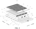
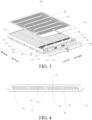
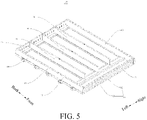
- a battery pack 100 according to an embodiment of the present disclosure will be described below with reference to FIGs. 1 to 5 .
- the battery pack 100 is applicable to vehicles.
- the battery pack 100 may include: a tray 10, at least one battery array 20 and at least one electrical connector 30.
- An accommodating groove 11 is provided on the tray 10, and the accommodating groove 11 is configured to accommodate the battery array 20.
- the battery array 20 is mounted in the accommodating groove 11 of the tray 10, and each of the at least one battery array 20 consists mainly of multiple batteries 21.
- the battery array 20 consisting of multiple batteries 21 is arranged in the accommodating groove 11, and the accommodating groove 11 can provide enough space to install the battery array 20, so the battery array 20 can supply energy for the battery pack 100 stably without external interference, thereby improving the stability of the battery pack 100.
- At least one through hole 12 is provided on a side wall of the accommodating groove 11; and the battery 21 in the battery array 20 arranged in the accommodating groove 11 is provided with an electrode terminal 22 at a side close to the through hole 12.
- the at least one electrical connector 30 is arranged in the accommodating groove 11, and the at least one electrical connector 30 is connected to the electrode terminals 22 of at least two batteries.
- the through hole 12 allows the electrode terminals 22 and the electrical connector 30 to be exposed. Namely, the at least one electrical connector 30 is mounted in the accommodating groove 11, and the at least one electrical connector 30 is connected between the electrode terminals 22 of at least two batteries 21.
- the electrode terminals 22 of at least two batteries 21 in the battery array 20 are connected through the at least one electrical connector 30, so that at least two batteries 21 are connected to each other, to generate the energy of the battery pack 100 together.
- the electrical connector 30 can connect two adjacent or spaced batteries 21 in series or connect two adjacent or spaced batteries 21 in parallel. or connect three or more batteries 21 in parallel.
- the through hole 12 provides a mounting space for the electrical connector 30 connecting the electrode terminals 22 of two batteries 21.
- the electrical connector 30 is connected to the electrode terminals 22 of the batteries 21 via the through hole 12. This eliminates the need of performing the connection procedure of the electrode terminals 22 of the battery array 20 to the electrical connector 30 outside the tray 10, thereby reducing the difficulty in the manufacturing of the battery pack 100, optimizing the process design, avoiding the wear of the electrical connector 30, and thus extending the life of the battery pack 100.
- the tray 10 includes: a bottom plate 17 and side beams 13 peripherally arranged around the bottom plate 17.
- the bottom plate 17 and the side beams 13 jointly define the accommodating groove 11.
- the side beams 13 include a first side beam and a second side beam which are oppositely arranged along a first direction.
- the first direction is a length direction of the battery pack 100 or a width direction of the battery pack 100.
- the tray 10 may mainly include: multiple side beams 13, and the multiple side beams 13 are connected and fixed to one another in sequence.
- the multiple side beams 13 are elevated beams higher than the bottom plate 17, the multiple side beams 13 connected to one another in sequence define the mounting space of the battery array 20 together with the bottom plate 17, so as to ensure the mounting reliability of the battery array 20.
- the length of the battery pack 100 is a front-back direction as shown in FIG. 1
- the width direction of the battery pack 100 is a left-right direction as shown in FIG. 1 .
- the multiple side beams 13 are all made of materials with good heat dissipation performance and high strength. This is because the battery array 20 will generate a lot of heat during operation, and side beams 13 with good heat dissipation performance can reduce the temperature of the battery array 20 to a certain extent, thereby ensuring the normal operation of the battery array 20, and avoiding the occurrence of safety accidents. Moreover, the side beams 13 with high strength can protect the battery array 20, to prevent the damage of the battery array 20 caused when the battery pack 100 is collided and squeezed, causing safety accidents, so as to extend the life of the battery pack 100. The side beams 13 may further have good flame retardancy, so when the battery array 20 is overheated and undergoes spontaneous combustion due to abnormal operation, the side beams 13 can prevent the battery array 20 from further combustion, thereby improving the safety of the battery pack 100.
- the battery pack 100 when traveling with the vehicle on the road, the battery pack 100 is most likely to receive the collision from a direction vertical to the vehicle's driving direction, that is, the left and right sides of the battery pack 100. Therefore, at least one of the first side beam and the second side beam is designed with the through hole 12, so that the mounting and connection position of the electrode terminal 22 of the battery 21 in the battery array 20 to the electrical connector 30 is located in the driving direction of the vehicle. Such an arrangement can reduce the risk of safety accidents of the battery array 20 after the vehicle is collided, thereby improving the safety and reliability of the vehicle and the battery pack 100.
- the first side beam and the second side beam are both provided with a through hole 12.
- the side beam 13 provided with the through hole 12 includes: an upper side beam 15 and a lower side beam 16, where the upper side beam 15 and the lower side beam 16 are spaced apart vertically, and the upper side beam 15 and the lower side beam 16 are connected between two side beams 13.
- the through hole 12 is located between the upper side beam 15 and the lower side beam 16.
- one of the first side beam and the second side beam is designed with the through hole 12
- the side beam 13 designed with the through hole 12 mainly includes the upper side beam 15 and the lower side beam 16 located below the upper side beam 15.
- the upper side beam 15 is connected to two adjacent side beams 13, the lower side beam 16 is also connected to the two adjacent side beams 13, and there is a distance between the upper side beam 15 and the lower side beam 16.
- the position of the through hole 12 can be defined by the spaced arrangement of the upper side beam 15 and the lower side beam 16, whereby the process structure is optimized. Moreover, the arrangement of the upper side beam 15 and the lower side beam 16 ensures the structural reliability of the tray 10.
- At least two sets battery arrays 20 are provided. If multiple sets of battery arrays 20 are designed, when a battery 21 is damaged and needs to be repaired and replaced, only the damaged set is repaired and replaced. This avoids the waste caused by the maintenance and replacement of the multiple sets of battery arrays 20 on a whole, to save the cost of maintenance and replacement. Moreover, the use of multiple sets of battery arrays 20 can increase the contact area between the battery arrays 20 and the ambient air, to effectively improve the heat dissipation effect of the battery pack 100, and thus improve the safety performance of the battery pack 100.
- the bottom plate 17 is provided with at least one partition beam 18 extending along the first direction, and the at least one partition beam 18 divides the accommodating groove 11 into multiple sub-grooves, where at least one set of battery array 20 is arranged in the sub-groove.
- the tray 10 may further include the at least one partition beam 18, and the bottom plate 17 is mounted below the accommodating groove 11 defined by the multiple side beams 13 connected in sequence.
- the number of battery array 20 in each sub-groove can be the same, or different.
- the bottom plate 17 has good flame retardancy and heat dissipation performance, to effectively reduce the temperature of the battery array 20 during operation and prevent the burning of the battery pack 100 caused by a too high temperature, thereby extending the life of the battery pack 100, and avoiding the occurrence of safety accidents.
- the at least one partition beam 18 is mounted on the bottom plate 17, and the at least one partition beam 18 extends on the bottom plate 17 along the first direction.
- the partition beam 18 can space adjacent battery arrays 20 apart, to avoid the mutual influence of adjacent battery arrays 20.
- the partition beam 18 also has good flame retardancy. In such an arrangement, when one set of battery array 20 burns due to a too high temperature, the partition beam 18 can prevent the fire from spreading to another set of battery array 20, to control the fire to the greatest extent, thereby improving the safety performance of the battery pack 100 and avoiding the occurrence of safety accidents.
- the partition beam 18 has good heat dissipation performance. Since multiple sets of battery arrays 20 are spaced apart by the at least one partition beam 18, the contact area between the battery array 20 and the at least one partition beam 18 is increased while the energy of the battery pack 100 is ensured by the multiple sets of battery arrays 20.
- the good heat dissipation performance of the partition beam 18 can effectively reduce the temperature of the battery array 20, increase the safety performance of the battery pack 100, avoid the occurrence of safety accidents.
- the partition beam 18 is arranged between two adjacent battery arrays 20, the number of the partition beams 18 is one less than the number of the battery arrays 20.
- the at least one partition beam 18 is evenly distributed on the bottom plate 17, to divide the accommodating groove 11 equally into multiple spaces of the same size, where batteries in the battery array 20 mounted in each space are exactly the same in terms of the number and volume.
- Each battery array 20 is allowed for even heat dissipation, to prevent accidents due to local high temperature caused by uneven heat dissipation.
- the at least one electrical connector 30 includes at least one first electrical connector 31 and at least one second electrical connector 32.
- the electrode terminals 22 of two adjacent batteries 21 in a same set of battery array 20 are connected by the first electrical connector 31, and the electrode terminals 22 of two adjacent batteries 21 located at two sides of the separation beam 18 are connected by the second electrical connector 32.
- one battery 21 is designed with two electrode terminals 22 that are a positive electrode terminal 22 and a negative electrode terminal 22 respectively.
- the upper one is the positive electrode terminal 22
- the lower one is the negative electrode terminal 22.
- the first electrical connector 31 When the first electrical connector 31 is connected to the electrode terminals 22 of two adjacent batteries in the same set of battery array 20, one end of the first electrical connector 31 is connected to the positive electrode terminal 22 of one of the batteries 21, and the other end is connected to the negative electrode terminal 22 of the other battery 21, whereby the two adjacent batteries 21 are connected to each other,
- the second electrical connector 32 When the second electrical connector 32 is connected to the electrode terminals 22 of two adjacent batteries 21 located at two sides of the partition beam 18, one end of the second electrical connector 32 is connected to the positive electrode terminal 22 of one of the batteries 21, and the other end is connected to the negative electrode terminal 22 of the other battery 21, whereby the two adjacent batteries 21 are connected to each other, Therefore, the current follows into the positive electrode terminal 22 and out of the negative electrode terminal 22, to constantly output energy to the outside.
- the first electrical connector 31 and the second electrical connector 32 are both a connection sheet, and length directions of the first electrical connector 31 and the second electrical connector 32 are inclined relative to the bottom plate 17.
- the length of the second electrical connector 32 is greater than the length of the first electrical connector 31, and the inclination angle of the second electrical connector 32 relative to the bottom plate 17 is smaller than the inclination angle of the first electrical connector 31 relative to the bottom plate 17.
- the distance in the vertical direction between two electrode terminals 22 connected by the second electrical connector 32 is the same as the distance in the vertical direction between two electrode terminals 22 connected by the first electrical connector 31.
- the distance in the horizontal direction between two electrode terminals 22 connected by the second electrical connector 32 is longer than the distance in the horizontal direction between two electrode terminals 22 connected by the first electrical connector 31. Therefore, it can be understood that according to the Pythagorean theorem, the straight-line distance between two electrode terminals 22 connected by the second electrical connector 32 is longer than the straight-line distance between two electrode terminals 22 connected by the first electrical connector 31. Namely, the second electrical connector 32 is longer than the first electrical connector 31.
- the electrical connector 30 when the electrical connector 30 is connected to two adjacent batteries 21, one end of the electrical connector 30 is connected to the upper positive electrode terminal 22 of one of the batteries 21, and the other end is connected to the lower negative electrode terminal 22 of the other battery 21. Therefore, when the electrical connector 30 is connected to the electrode terminals 22 of two adjacent batteries 21, it is inclined relative to the bottom plate 17. According to the law of sine and cosine, the inclination angle of the second electrical connector 32 relative to the bottom plate 17 is smaller than the inclination angle of the first electrical connector 31 relative to the bottom plate 17. Namely, the angle formed by the second electrical connector 32 with respect to the bottom plate 17 is smaller than the angle formed by the first electrical connector 31 with respect to the bottom plate 17.
- the multiple batteries 21 in the battery array 20 are arranged in sequence along the second direction.
- the battery 21 has a length extending along the first direction, and the electrode terminal 22 of the battery 21 is arranged on one side of the battery 21 in the first direction.
- the thickness of the battery 21 extends along the second direction.
- the first direction is the length direction of the battery pack 100
- the second direction is the width direction of the battery pack 100.
- the first direction is the width direction of the battery pack 100
- the second direction is the length direction of the battery pack 100.
- one through hole 12 is provided, and the through hole 12 corresponds to the electrode terminals 22 of batteries in all the battery arrays 20.
- the electrode terminals 22 of batteries 21 in the multiple sets of battery array 20 are all arranged facing the through hole 12.
- multiple sets of battery arrays 20 can be mounted and arranged in the accommodating groove 11 of the tray 10 first, and then the electrical connectors 30 are connected to the electrode terminals 22 of all batteries by welding via the through hole 12. This eliminates the need of performing the connection procedure of the electrode terminals 22 of the battery array 20 to the electrical connector 30 outside the tray 10, thereby simplifying the assembly process of the battery pack 100, and optimizing the process flow.
- such an arrangement can also facilitate the maintenance of the battery array 20 directly via the through hole 12, to avoid the maintenance of the battery array 20 after removal from the accommodating groove 11, thereby saving the cost and reducing the difficulty of maintenance.
- the battery pack 100 further includes a power distribution box 40 electrically connected to the battery array 20.
- the power distribution box 40 is arranged in the accommodating groove 11, and the power distribution box 40 is located between the battery array 20 and the side beam 13 provided with the through hole 12, to maintain the power distribution box 40 via the through hole 12. Namely, after the battery array 20 is mounted and arranged in the tray 10, there is still remaining space between the battery array 20 and the side beam 13 designed with the through hole 12 of the tray 10.
- the power distribution box 40 is mounted and arranged between the battery array 20 and the side beam 13 designed with the through hole 12 of the tray 10, in such a manner that the power distribution box 40 is connected to the battery array 20 at the side close to the battery array 20.
- the current generated by the battery array 20 is thus allowed to flow into the power distribution box 40, and stably output to the outside from the side of the power distribution box 40 away from the battery array 20 after control, transform, distribution and other operations in the power distribution box 40.
- the operation can also be performed via the through hole 12 directly, without taking out the power distribution box 40, to facilitate the maintenance and inspection of the power distribution box 40.
- the battery pack 100 further includes an upper cover 50, which is covered on the top of the tray 10, and internally provided with a flow channel.
- the battery pack 100 further includes the upper cover 50.
- the upper cover 50 is mounted at the top the accommodating groove 11, and the upper cover 50, together with the bottom plate 17 and the multiple side beams 13, defines a closed accommodating groove 11, to prevent foreign matters from entering and damaging the battery array 20, and extend the life of the battery array 20.
- the upper cover 50 can also be integrated to the vehicle body.
- the upper cover 50 is internally designed with a flow channel, and the liquid in the flow channel flows to well dissipate the heat absorbed by the upper cover 50, thereby effectively reducing the temperature of the battery array 20 and improving the safety performance of the battery pack 100.
- the upper cover 50 is a direct cooling plate.
- the upper cover 50 includes a second heat dissipation plate 51 and a first heat dissipation plate 52, where the second heat dissipation plate 51 and the first heat dissipation plate 52 jointly define the flow channel.
- the first heat dissipation plate 52 is formed with a convex flow channel
- the second heat dissipation plate 51 is arranged below the first heat dissipation plate 52 to seal the flow channel.
- the upper cover 50 is a direct cooling plate.
- the second heat dissipation plate 51 and the first heat dissipation plate 52 can both be aluminum plates.
- the second heat dissipation plate 51 is covered on the top of the accommodating groove 11, to seal the top of the accommodating groove 11. In this way, the weight of the battery pack 100 is reduced, and the upper cover 50 is ensured to have good heat dissipation performance. In addition, the high strength of the heat dissipation plate 51 can protect the battery array 20 against damage when the battery pack 100 is collided and squeezed.
- the first heat dissipation plate 52 is mounted and arranged above the second heat dissipation plate 51, and the first heat dissipation plate 52 is formed with a convex flow channel through a stamping process.
- the flow channel is tortuously arranged on the first heat dissipation plate 52. This arrangement can increase the length of the flow channel on the first heat dissipation plate 52 of the same area, to improve the heat dissipation of the upper cover 50 and reduce the temperature of the battery array 20 as much as possible.
- the first heat dissipation plate 52 and the second heat dissipation plate 51 are connected to each other by brazing, to achieve the sealing of the flow channel.
- the sealed flow channel is hollow and communicates with the exterior.
- a cooling channel is defined in the interior of the hollow flow channel, and a gaseous coolant is provided in the cooling channel.
- the gaseous coolant absorbing heat in the cooling channel can flow in the hollow flow channel, to reduce the temperature of the battery array 20. Therefore, in one embodiment, the heat dissipation effect of the upper cover 50 is improved.
- a seal gasket 53 or a sealant is provided between the edge of the upper cover 50 and the tray 10.
- the design of the seal gasket 53 or the sealant between the peripheral edge of the upper cover 50 and the tray 10 can increase the tightness of the upper cover 50 to the tray 10 and prevent foreign matters from entering and damaging the battery array 20 in one embodiment.
- the seal gasket 53 or the sealant can also reduce the wear caused by the direct contact of the metal upper cover 50 and the tray 10, thereby extending the life of the battery pack 100.
- the battery pack 100 further includes: a sealing cover 60 for sealing the at least one through hole 12, where the sealing cover 60 is detachably connected to the tray 10.
- the sealing cover 60 is mounted on the side of the through hole 12 away from the battery array 20.
- the sealing cover 60 can be used to seal the through hole 12, to prevent foreign matters from entering via the through hole 12 and damaging the battery array 20, so as to extend the life of the battery pack 100.
- the sealing cover 60 can be conveniently removed to maintain the battery array 20 via the through hole 12, thereby saving the cost of maintenance, and optimizing the structure design.
- a seal gasket 53 or a sealant is provided between the seal cover 60 and the tray 10.
- the design of the seal gasket 53 or the sealant between the seal cover 60 and the tray 10 can increase the tightness of the seal cover 60 to the tray 10 and prevent foreign matters from entering and damaging the battery array 20 in one embodiment.
- the seal gasket 53 or the sealant can also reduce the wear caused by the direct contact of the metal seal cover 60 and the tray 10, thereby extending the life of the battery pack 100.
- a vehicle includes a battery pack 100 according to above embodiment.
- the battery pack 100 is mounted on a chassis of the vehicle.
- the battery pack 100 can supply, to the vehicle, power needed for driving the vehicle on the road, make the vehicle more environmentally friendly and safe, and improve the user experience.
- orientation or position relationships indicated by the terms such as “center”, “lateral”, “length”, “width”, “thickness”, “up”, “down”, “front”, “back”, “left”, “right”, “vertical”, “horizontal”, “top”, “bottom”, “inside”, “outside”, “axial”, and “radial” are based on orientation or position relationships shown in the accompanying drawings, and are used only for ease and brevity of illustration and description of the present disclosure, rather than indicating or implying that the mentioned apparatus or component must have a particular orientation or must be constructed and operated in a particular orientation. Therefore, such terms should not be construed as limiting of the present disclosure.
- "a plurality of” means two or more.
Landscapes
- Chemical & Material Sciences (AREA)
- Chemical Kinetics & Catalysis (AREA)
- Electrochemistry (AREA)
- General Chemical & Material Sciences (AREA)
- Engineering & Computer Science (AREA)
- Manufacturing & Machinery (AREA)
- Sustainable Development (AREA)
- Life Sciences & Earth Sciences (AREA)
- Aviation & Aerospace Engineering (AREA)
- Sustainable Energy (AREA)
- Power Engineering (AREA)
- Transportation (AREA)
- Mechanical Engineering (AREA)
- Battery Mounting, Suspending (AREA)
- Connection Of Batteries Or Terminals (AREA)
- Secondary Cells (AREA)
Applications Claiming Priority (2)
| Application Number | Priority Date | Filing Date | Title |
|---|---|---|---|
| CN202010462922.XA CN113809479B (zh) | 2020-05-27 | 2020-05-27 | 电池包以及车辆 |
| PCT/CN2021/083300 WO2021238379A1 (zh) | 2020-05-27 | 2021-03-26 | 电池包以及车辆 |
Publications (2)
| Publication Number | Publication Date |
|---|---|
| EP4131607A1 true EP4131607A1 (de) | 2023-02-08 |
| EP4131607A4 EP4131607A4 (de) | 2024-03-20 |
Family
ID=78745497
Family Applications (1)
| Application Number | Title | Priority Date | Filing Date |
|---|---|---|---|
| EP21814471.5A Pending EP4131607A4 (de) | 2020-05-27 | 2021-03-26 | Batteriepack und fahrzeug |
Country Status (7)
| Country | Link |
|---|---|
| US (1) | US20230198102A1 (de) |
| EP (1) | EP4131607A4 (de) |
| JP (1) | JP7522859B2 (de) |
| KR (1) | KR102854147B1 (de) |
| CN (1) | CN113809479B (de) |
| CA (1) | CA3178213A1 (de) |
| WO (1) | WO2021238379A1 (de) |
Cited By (3)
| Publication number | Priority date | Publication date | Assignee | Title |
|---|---|---|---|---|
| WO2024179724A1 (en) * | 2023-02-28 | 2024-09-06 | Stellantis Auto Sas | Battery pack for electric vehicle, and electric vehicle |
| EP4439780A1 (de) * | 2023-03-26 | 2024-10-02 | Samsung SDI Co., Ltd. | Batteriemodulbaugruppe |
| EP4557480A4 (de) * | 2023-03-30 | 2026-02-25 | Svolt Energy Technology Wuxi Co Ltd | Batteriekastenkörper und leistungsvorrichtung damit |
Families Citing this family (6)
| Publication number | Priority date | Publication date | Assignee | Title |
|---|---|---|---|---|
| US12283712B2 (en) | 2021-12-27 | 2025-04-22 | Lg Energy Solution, Ltd. | Battery pack and vehicle including the same |
| US20250364681A1 (en) * | 2022-01-25 | 2025-11-27 | Lg Energy Solution, Ltd. | Battery pack and vehicle including the same |
| PL4266464T3 (pl) * | 2022-02-25 | 2026-04-20 | Contemporary Amperex Technology (Hong Kong) Limited | Bateria, urządzenie zużywające energię oraz sposób i urządzenie do wytwarzania baterii |
| CN114744354B (zh) * | 2022-04-18 | 2024-04-05 | 香港城市大学深圳研究院 | 一种带有抗压承托功能的锂离子电池组件 |
| CN115207551B (zh) * | 2022-09-16 | 2022-11-15 | 中创新航科技股份有限公司 | 一种电池箱体及电池装置 |
| CN116544707A (zh) * | 2022-12-30 | 2023-08-04 | 奥动新能源汽车科技有限公司 | 电连接器组件及包含其的电池包 |
Family Cites Families (32)
| Publication number | Priority date | Publication date | Assignee | Title |
|---|---|---|---|---|
| JP3462714B2 (ja) * | 1997-06-04 | 2003-11-05 | 三洋電機株式会社 | パック電池 |
| WO2000030190A1 (en) * | 1998-11-17 | 2000-05-25 | C & D Technologies, Inc. | Selectable capacity fixed footprint lead-acid battery racking system with horizontal plates |
| JP3696097B2 (ja) * | 2001-01-30 | 2005-09-14 | 三洋電機株式会社 | パック電池とその製造方法 |
| JP2003031189A (ja) * | 2001-07-04 | 2003-01-31 | Deruko:Kk | 外装ボックスを有する蓄電池 |
| KR101087036B1 (ko) * | 2008-12-17 | 2011-11-25 | 주식회사 엘지화학 | 전극단자 연결장치 및 이를 포함하는 전지모듈 어셈블리 |
| JP2011204394A (ja) * | 2010-03-24 | 2011-10-13 | Panasonic Corp | 電池パック |
| US8642206B2 (en) * | 2010-11-04 | 2014-02-04 | Samsung Sdi Co., Ltd. | Battery module |
| US9196880B2 (en) * | 2011-01-26 | 2015-11-24 | Samsung Sdi Co., Ltd. | Battery module with offset battery cells |
| EP2650960B1 (de) * | 2011-01-26 | 2020-01-01 | LG Chem, Ltd. | Kühlelement mit verbesserter anordnungsproduktivität und batteriemodule damit |
| CN202268412U (zh) * | 2011-09-28 | 2012-06-06 | 上海比亚迪有限公司 | 一种车用动力电池包 |
| CN202434615U (zh) * | 2012-01-17 | 2012-09-12 | 重庆长安汽车股份有限公司 | 一种电动汽车电池模块组合装置 |
| JP2014044817A (ja) * | 2012-08-24 | 2014-03-13 | Toyota Motor Corp | 電源装置およびそれを搭載する車両 |
| JP6109926B2 (ja) * | 2013-03-29 | 2017-04-05 | 三洋電機株式会社 | 電池パック |
| JP2019032924A (ja) * | 2015-12-24 | 2019-02-28 | 三洋電機株式会社 | 電池パックと電池パックの製造方法 |
| JP2018032520A (ja) * | 2016-08-24 | 2018-03-01 | 株式会社Gsユアサ | 蓄電装置 |
| JP6709757B2 (ja) * | 2017-06-20 | 2020-06-17 | 矢崎総業株式会社 | バスバー構造 |
| JP2019075256A (ja) * | 2017-10-16 | 2019-05-16 | 株式会社日立製作所 | 二次電池モジュール |
| CN207368169U (zh) * | 2017-10-25 | 2018-05-15 | 北京美联桥科技发展有限公司 | 一种新能源汽车动力电池水冷散热板 |
| KR102364283B1 (ko) * | 2017-12-01 | 2022-02-16 | 주식회사 엘지에너지솔루션 | 방열 플레이트를 구비한 배터리 모듈 |
| CN208014762U (zh) * | 2017-12-19 | 2018-10-26 | 江苏楚汉新能源科技有限公司 | 用于电动汽车的电池模组 |
| CN207883764U (zh) * | 2018-01-17 | 2018-09-18 | 东莞市顺力电池有限公司 | 一种电池模组 |
| US11217847B2 (en) * | 2018-04-27 | 2022-01-04 | Ford Global Technologies, Llc | Polymer-based enclosure assemblies for electrified vehicle battery packs |
| JP2020038762A (ja) * | 2018-09-03 | 2020-03-12 | 日立オートモティブシステムズ株式会社 | 二次電池モジュール |
| CN109148782A (zh) * | 2018-09-25 | 2019-01-04 | 湖南科霸汽车动力电池有限责任公司 | 一种方形电池模组 |
| CN209374503U (zh) * | 2018-09-26 | 2019-09-10 | 浙江正泰电器股份有限公司 | 电池托盘 |
| CN209217036U (zh) * | 2018-10-09 | 2019-08-06 | 伟巴斯特车顶供暖系统(上海)有限公司 | 基于圆柱电池的标准模组结构、电池包及车辆 |
| US12230820B2 (en) * | 2019-01-09 | 2025-02-18 | Byd Company Limited | Power battery pack and electric vehicle |
| CN209993659U (zh) * | 2019-07-31 | 2020-01-24 | 深圳市誉娇诚科技有限公司 | 方便维护的动力电池装置 |
| CN210403972U (zh) * | 2019-08-23 | 2020-04-24 | 比亚迪股份有限公司 | 电池包的换热板组件和具有其的电池组件、电动汽车 |
| CN210245592U (zh) * | 2019-08-30 | 2020-04-03 | 蜂巢能源科技有限公司 | 电池拘束托盘 |
| MX2022005982A (es) * | 2019-11-21 | 2022-09-02 | Tesla Inc | Sistema de almacenamiento de energia integrado. |
| CN113889708B (zh) * | 2020-06-19 | 2022-11-11 | 比亚迪股份有限公司 | 车辆及其电池包 |
-
2020
- 2020-05-27 CN CN202010462922.XA patent/CN113809479B/zh active Active
-
2021
- 2021-03-26 KR KR1020227040464A patent/KR102854147B1/ko active Active
- 2021-03-26 EP EP21814471.5A patent/EP4131607A4/de active Pending
- 2021-03-26 CA CA3178213A patent/CA3178213A1/en active Pending
- 2021-03-26 WO PCT/CN2021/083300 patent/WO2021238379A1/zh not_active Ceased
- 2021-03-26 JP JP2022570367A patent/JP7522859B2/ja active Active
- 2021-03-26 US US17/923,419 patent/US20230198102A1/en active Pending
Cited By (3)
| Publication number | Priority date | Publication date | Assignee | Title |
|---|---|---|---|---|
| WO2024179724A1 (en) * | 2023-02-28 | 2024-09-06 | Stellantis Auto Sas | Battery pack for electric vehicle, and electric vehicle |
| EP4439780A1 (de) * | 2023-03-26 | 2024-10-02 | Samsung SDI Co., Ltd. | Batteriemodulbaugruppe |
| EP4557480A4 (de) * | 2023-03-30 | 2026-02-25 | Svolt Energy Technology Wuxi Co Ltd | Batteriekastenkörper und leistungsvorrichtung damit |
Also Published As
| Publication number | Publication date |
|---|---|
| KR20230005890A (ko) | 2023-01-10 |
| US20230198102A1 (en) | 2023-06-22 |
| CA3178213A1 (en) | 2021-12-02 |
| JP2023526403A (ja) | 2023-06-21 |
| EP4131607A4 (de) | 2024-03-20 |
| CN113809479B (zh) | 2023-02-10 |
| KR102854147B1 (ko) | 2025-09-04 |
| JP7522859B2 (ja) | 2024-07-25 |
| CN113809479A (zh) | 2021-12-17 |
| WO2021238379A1 (zh) | 2021-12-02 |
Similar Documents
| Publication | Publication Date | Title |
|---|---|---|
| EP4131607A1 (de) | Batteriepack und fahrzeug | |
| JP7685030B2 (ja) | 電池パック、車両及びエネルギー蓄積装置 | |
| EP3933955A1 (de) | Akkupack, energiespeichervorrichtung und elektrisches fahrzeug | |
| US20240106069A1 (en) | Battery module and electric vehicle | |
| CN102903875B (zh) | 一种增程型电动汽车电池组 | |
| US20240383538A1 (en) | Vehicle body floor assembly for vehicle and vehicle cross-reference to related applications | |
| CN118040209A (zh) | 电池及用电装置 | |
| KR20210133534A (ko) | 전지팩 및 이를 포함하는 디바이스 | |
| JP7806281B2 (ja) | 電池及び電力消費装置 | |
| KR102707154B1 (ko) | 전지용 박스 본체, 전지, 전기 장치, 전지 제조 방법 및 기기 | |
| CA3227987A1 (en) | Case of battery, battery, power consumption device, and method and device for manufacturing battery | |
| CN220021381U (zh) | 电池包箱体及电池包 | |
| KR20200058951A (ko) | 전기차용 배터리 팩 | |
| WO2024077605A1 (zh) | 电池和用电装置 | |
| CN112993474A (zh) | 电池包下箱体及电池包 | |
| CN120511402A (zh) | 电池装置及用电设备 | |
| WO2022144657A1 (en) | Battery pack and vehicle | |
| CN216085090U (zh) | 一种电池包及电池散热系统 | |
| CN207690956U (zh) | 一种新能源汽车电池的充电外壳 | |
| CN223871612U (zh) | 电池箱及用电设备 | |
| CN207530088U (zh) | 一种新能源汽车电池的散热小壳体 | |
| CN223023480U (zh) | 一种电池包和用电设备 | |
| CN117790973B (zh) | 电池包及用电装置 | |
| CN223285182U (zh) | 电池装置和用电设备 | |
| CN222749664U (zh) | 电芯、电池及用电装置 |
Legal Events
| Date | Code | Title | Description |
|---|---|---|---|
| STAA | Information on the status of an ep patent application or granted ep patent |
Free format text: STATUS: THE INTERNATIONAL PUBLICATION HAS BEEN MADE |
|
| PUAI | Public reference made under article 153(3) epc to a published international application that has entered the european phase |
Free format text: ORIGINAL CODE: 0009012 |
|
| STAA | Information on the status of an ep patent application or granted ep patent |
Free format text: STATUS: REQUEST FOR EXAMINATION WAS MADE |
|
| 17P | Request for examination filed |
Effective date: 20221026 |
|
| AK | Designated contracting states |
Kind code of ref document: A1 Designated state(s): AL AT BE BG CH CY CZ DE DK EE ES FI FR GB GR HR HU IE IS IT LI LT LU LV MC MK MT NL NO PL PT RO RS SE SI SK SM TR |
|
| DAV | Request for validation of the european patent (deleted) | ||
| DAX | Request for extension of the european patent (deleted) | ||
| A4 | Supplementary search report drawn up and despatched |
Effective date: 20240215 |
|
| RIC1 | Information provided on ipc code assigned before grant |
Ipc: H01M 10/6561 20140101ALI20240209BHEP Ipc: H01M 10/6557 20140101ALI20240209BHEP Ipc: H01M 10/6556 20140101ALI20240209BHEP Ipc: H01M 10/6554 20140101ALI20240209BHEP Ipc: H01M 10/653 20140101ALI20240209BHEP Ipc: H01M 10/647 20140101ALI20240209BHEP Ipc: H01M 10/625 20140101ALI20240209BHEP Ipc: H01M 10/613 20140101ALI20240209BHEP Ipc: H01M 50/507 20210101ALI20240209BHEP Ipc: H01M 50/296 20210101ALI20240209BHEP Ipc: H01M 50/271 20210101ALI20240209BHEP Ipc: H01M 50/262 20210101ALI20240209BHEP Ipc: H01M 50/244 20210101ALI20240209BHEP Ipc: H01M 50/224 20210101ALI20240209BHEP Ipc: H01M 50/213 20210101ALI20240209BHEP Ipc: H01M 50/204 20210101ALI20240209BHEP Ipc: H01M 50/249 20210101ALI20240209BHEP Ipc: H01M 50/209 20210101AFI20240209BHEP |