EP4131647A1 - Radarantennenanordnung und radarsystem - Google Patents
Radarantennenanordnung und radarsystem Download PDFInfo
- Publication number
- EP4131647A1 EP4131647A1 EP21190101.2A EP21190101A EP4131647A1 EP 4131647 A1 EP4131647 A1 EP 4131647A1 EP 21190101 A EP21190101 A EP 21190101A EP 4131647 A1 EP4131647 A1 EP 4131647A1
- Authority
- EP
- European Patent Office
- Prior art keywords
- radar
- antenna assembly
- vehicle
- radar antenna
- surface portion
- Prior art date
- Legal status (The legal status is an assumption and is not a legal conclusion. Google has not performed a legal analysis and makes no representation as to the accuracy of the status listed.)
- Granted
Links
Images



Classifications
-
- H—ELECTRICITY
- H01—ELECTRIC ELEMENTS
- H01Q—ANTENNAS, i.e. RADIO AERIALS
- H01Q19/00—Combinations of primary active antenna elements and units with secondary devices, e.g. with quasi-optical devices, for giving the antenna a desired directional characteristic
- H01Q19/10—Combinations of primary active antenna elements and units with secondary devices, e.g. with quasi-optical devices, for giving the antenna a desired directional characteristic using reflecting surfaces
- H01Q19/12—Combinations of primary active antenna elements and units with secondary devices, e.g. with quasi-optical devices, for giving the antenna a desired directional characteristic using reflecting surfaces wherein the surfaces are concave
- H01Q19/17—Combinations of primary active antenna elements and units with secondary devices, e.g. with quasi-optical devices, for giving the antenna a desired directional characteristic using reflecting surfaces wherein the surfaces are concave the primary radiating source comprising two or more radiating elements
-
- H—ELECTRICITY
- H01—ELECTRIC ELEMENTS
- H01Q—ANTENNAS, i.e. RADIO AERIALS
- H01Q1/00—Details of, or arrangements associated with, antennas
- H01Q1/27—Adaptation for use in or on movable bodies
- H01Q1/32—Adaptation for use in or on road or rail vehicles
- H01Q1/3208—Adaptation for use in or on road or rail vehicles characterised by the application wherein the antenna is used
- H01Q1/3233—Adaptation for use in or on road or rail vehicles characterised by the application wherein the antenna is used particular used as part of a sensor or in a security system, e.g. for automotive radar, navigation systems
-
- H—ELECTRICITY
- H01—ELECTRIC ELEMENTS
- H01Q—ANTENNAS, i.e. RADIO AERIALS
- H01Q1/00—Details of, or arrangements associated with, antennas
- H01Q1/27—Adaptation for use in or on movable bodies
- H01Q1/32—Adaptation for use in or on road or rail vehicles
- H01Q1/325—Adaptation for use in or on road or rail vehicles characterised by the location of the antenna on the vehicle
- H01Q1/3283—Adaptation for use in or on road or rail vehicles characterised by the location of the antenna on the vehicle side-mounted antennas, e.g. bumper-mounted, door-mounted
-
- H—ELECTRICITY
- H01—ELECTRIC ELEMENTS
- H01Q—ANTENNAS, i.e. RADIO AERIALS
- H01Q1/00—Details of, or arrangements associated with, antennas
- H01Q1/27—Adaptation for use in or on movable bodies
- H01Q1/32—Adaptation for use in or on road or rail vehicles
- H01Q1/325—Adaptation for use in or on road or rail vehicles characterised by the location of the antenna on the vehicle
- H01Q1/3291—Adaptation for use in or on road or rail vehicles characterised by the location of the antenna on the vehicle mounted in or on other locations inside the vehicle or vehicle body
-
- H—ELECTRICITY
- H01—ELECTRIC ELEMENTS
- H01Q—ANTENNAS, i.e. RADIO AERIALS
- H01Q19/00—Combinations of primary active antenna elements and units with secondary devices, e.g. with quasi-optical devices, for giving the antenna a desired directional characteristic
- H01Q19/10—Combinations of primary active antenna elements and units with secondary devices, e.g. with quasi-optical devices, for giving the antenna a desired directional characteristic using reflecting surfaces
- H01Q19/12—Combinations of primary active antenna elements and units with secondary devices, e.g. with quasi-optical devices, for giving the antenna a desired directional characteristic using reflecting surfaces wherein the surfaces are concave
- H01Q19/13—Combinations of primary active antenna elements and units with secondary devices, e.g. with quasi-optical devices, for giving the antenna a desired directional characteristic using reflecting surfaces wherein the surfaces are concave the primary radiating source being a single radiating element, e.g. a dipole, a slot, a waveguide termination
- H01Q19/132—Horn reflector antennas; Off-set feeding
Definitions
- the present disclosure relates to vehicle radar antenna assemblies and vehicle radar systems.
- ADAS advanced driver assistance systems
- Vehicle radar systems are also important for autonomous driving (AD) applications. Objects in the environment of a vehicle may be identified by means of transmitting a primary radar signal into the traffic space, to receive a secondary radar signal reflected by at least one object and to process the secondary radar signal.
- automotive radar systems are provided as modules comprising an integrated radar circuit and a radar antenna assembly arranged on a common board.
- the antenna aperture and the antenna gain of such modules is limited. Further, due to the plurality of constructional elements which are necessary for such a module, the fabrication costs are comparatively high. Radar antenna assemblies having a feed horn and a reflector are difficult to install on vehicles because of increasingly strict space restrictions.
- the present disclosure provides a radar antenna assembly and a radar system according to the independent claims. Embodiments are given in the subclaims, the description and the drawings.
- the present disclosure is directed at a radar antenna assembly for a vehicle, the radar antenna assembly comprising a feed horn configured to transmit and/or receive radar signals and a metallic component of the vehicle, wherein the metallic component of the vehicle comprises a curved or faceted surface portion and the feed horn is positioned such that the curved or faceted surface portion forms a reflector for the feed horn.
- the metallic component of the vehicle may be at least partially used as an antenna reflector.
- the material costs may be reduced.
- a separate reflector may be omitted.
- the metallic component of the vehicle may have a relatively large size and thus provide a large reflector surface. Therefore, the aperture and the gain of the radar antenna assembly may be considerably extended compared to radar building blocks.
- the radar antenna assembly may further comprise one or more of the following features:
- the metallic component may form at least a part of a crash beam, a bumper, a pillar or a door of the vehicle.
- the feed horn may be fixed to the metallic component of the vehicle. In a mounted state of the metallic component of the vehicle, the curved or faceted surface portion may face away from a center of the vehicle.
- the curved or faceted surface portion may be cylindrically or elliptically shaped.
- the feed horn may comprise a waveguide member for a connection of the feed horn to a radar circuit, wherein the metallic component comprises a passage through which the waveguide member is guided. The passage may be located in a central region of the curved or faceted surface portion.
- the passage may be located outside the curved or faceted surface portion.
- the feed horn may comprise a plurality of individual antenna elements and a plurality of waveguide members for respective connections of the antenna elements to the radar circuit.
- the waveguide members may be arranged in a common conduit which is guided through the passage.
- the individual antenna elements may be output ends of the waveguides. At least two of the individual antenna elements may be connected to separate transmitters of a radar circuit.
- the metallic component may have a recess and an insert member insertable into the recess, wherein the insert member comprises the curved or faceted surface portion.
- the metallic component forms at least a part of a crash beam, a bumper, a pillar or a door of the vehicle.
- metallic structures are already present in a motor vehicle and may be used as a component of a radar antenna assembly.
- the metallic component may have a surface area of at least 400 cm 2 , in particular of at least 1000 cm 2 .
- a relatively large reflector size enhances the gain and the aperture of the radar antenna assembly.
- the feed horn is fixed to the metallic component of the vehicle.
- the curved or faceted surface portion faces away from a center of the vehicle to enable a monitoring of the surrounding of the vehicle.
- the curved or faceted surface portion may be concave with respect to the feed horn.
- the curved or faceted surface portion is cylindrically or elliptically shaped.
- the shape of the curved or faceted surface portion may be adapted to the requirements of the application.
- the feed horn may be positioned in a focal region of the reflector.
- the feed horn comprises a waveguide member for a connection of the feed horn to a radar circuit and wherein the metallic component comprises a passage through which the waveguide member is guided.
- the waveguide may be at least partially made from a plastic material.
- the passage is located in a central region of the curved or faceted surface portion. This facilitates the provision of an at least essentially symmetric beam shape.
- the passage may be located outside the curved or faceted surface portion. The connection of the feed horn to a control board is thereby simplified.
- the radar antenna assembly has an offset reflector design.
- the space occupied by the radar antenna assembly in front of the metallic component is thereby minimized.
- the sidelobe suppression and the polarization purity may be increased.
- the radar antenna assembly may have a Cassegrain design.
- the feed horn comprises a plurality of individual antenna elements and a plurality of waveguide members for respective connections of the antenna elements to the radar circuit. An advanced beam steering may thus be provided.
- the waveguide members are arranged in a common conduit which is guided through the passage.
- the conduit protects the waveguide members and improves the stability of the assembly.
- the individual antenna elements are output ends of the waveguides.
- the output ends may be shaped dependent on the requirements of the application.
- At least two of the individual antenna elements are connected to separate transmitters of a radar circuit.
- several transmitter channels may be provided to enable a beam steering.
- the metallic component has a recess and an insert member insertable into the recess, wherein the insert member comprises the curved or faceted surface portion.
- a manufacturer of the radar system may easily pre-fabricate a module comprising the insert member and deliver the module to a manufacturer of the vehicle, who inserts the insert member into the recess of an existing crash beam or the like.
- the present disclosure is directed at a radar antenna assembly for a vehicle, the radar antenna assembly comprising a feed horn configured to transmit and/or receive radar signals and a metallic plate member, wherein the metallic plate member comprises a curved or faceted surface portion, wherein the feed horn is fixed to the metallic plate member such that the curved or faceted surface portion forms a reflector for the feed horn and wherein the metallic plate member is configured for an insertion in a recess of a metallic component of the vehicle.
- the present disclosure is directed at a radar system for a vehicle, the radar system comprising a radar antenna assembly as disclosed above and a radar circuit for generating and/or processing radar signals, wherein the radar circuit is configured for a multiplex operation, a multiple input multiple output (MIMO) operation and/or a frequency scan operation of the radar antenna assembly.
- MIMO multiple input multiple output
- the radar circuit may be formed on a printed circuit board. This enables a space saving construction.
- the radar circuit may comprise a monolithic microwave integrated circuit (MMIC).
- MMIC monolithic microwave integrated circuit
- the radar circuit may be arranged in a housing which is attached to the metallic component of the vehicle. The housing protects the radar circuit from dust, splash water and the like.
- the present disclosure is directed at a vehicle comprising a chassis, a body and a radar system comprising a radar antenna assembly as disclosed herein, wherein the metallic component is a portion of the chassis or the body.
- Fig. 1 schematically depicts a motor vehicle 11, also called a host vehicle, and a radar system 13 mounted to a front portion of the motor vehicle 11.
- the radar system 13 is connected to an electronic processing device 15, for example an advanced driver assistance system or an autonomous driving system.
- the motor vehicle 11 is moving in a driving direction 17 in a traffic space 19, for example a road.
- Objects 20, such as other vehicles, pedestrians or stationary obstacles, may be located in the traffic space 19.
- the radar system 13 is configured for transmitting at least one primary radar signal 21 into the traffic space 19 and for detecting objects 20 present in the traffic space 19 on the basis of at least one secondary radar signal 22 reflected by the objects 20, as is generally known in the art.
- the radar system 13 comprises a radar antenna assembly 25 for transmitting primary radar signals 21 into the traffic space 19 and for receiving secondary radar signals 22 reflected by objects 20 present in the traffic space 19.
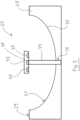
- the radar antenna assembly 25, which is schematically depicted in Figs. 2 and 3 , is integrated in a crash beam 27 of the vehicle 11 ( Fig. 1 ).
- the crash beam 27, which may be made from steel or another metal, is fixedly connected to a frame or a body of the vehicle 11.
- the crash beam 27 may be configured as a hollow profile.
- a front surface 29 of the crash beam 27 comprises a curved surface portion 31 in the form of a depression.
- the radar antenna assembly 25 comprises a feed horn 33 and a reflector 35.
- the radar antenna assembly 25 is of the reflector type.
- the reflector 35 is formed by the curved surface portion 31 of the crash beam 27.
- the curved surface portion 31 may be spherically, parabolically, cylindrically or elliptically shaped.
- the feed horn 33 enters the reflector 35 in a central region of the curved surface portion 31.
- the feed horn 33 comprises a plurality of antenna elements 37 pointing to the reflector 35.
- the antenna elements 37 may be configured as end portions of plastic waveguide members, not shown, which are received in a common conduit 39 and guided, via a passage 36 of the crash beam 27, through the curved surface portion 31.
- a feed horn having a single antenna element 37 may be sufficient.
- the waveguide members are connected to transmitters and/or receivers of a radar circuit (not shown) of the radar system 13.
- the radar circuit may be configured to generate and process radar signals, as is generally known.
- the radar circuit may be configured as a monolithic microwave integrated circuit (MMIC).
- MMIC monolithic microwave integrated circuit
- the radar circuit may be arranged in a cavity of the crash beam 27. Thus, only little installation space is required for the radar system 13.
- the crash beam 27 may have a recess and an insert member comprising the curved surface portion 31, wherein the insert member is insertable into the recess.
- the reflector 35 may be configured as an insert member.
- a manufacturer of the radar system 13 may easily pre-fabricate a module comprising the reflector 35 and deliver the module to a manufacturer of the vehicle 11, who inserts the reflector 35 into the recess of the crash beam 27.
- Fig. 4 shows a radar antenna assembly 25' according to another embodiment.
- the depicted radar antenna assembly 25' has an offset reflector configuration.
- the feed horn 33' is located outside the curved surface portion 31. Due to the illumination of the reflector 35 from the side, the connection of the feed horn 33 to the corresponding control board is simplified.
- the offset reflector configuration provides for an improved sidelobe suppression and for an increased polarization purity.
- the feed horn 33, 33' may enter the reflector 35 at other positions to adapt the side lobe suppression and the polarization purity as desired.
- a faceted portion of the crash beam 27 may form the reflector 35.
- the feed horn 33, 33' may be operated in a frequency scanning mode to provide a large beam steering range with only one transmitter. Further beam steering capabilities may be achieved by operating a feed horn 33, 33' comprising several transmitters in a phased array mode. A combination of a frequency scanning and a phased array scanning provides a particularly large beam steering range.
- the disclosed radar system 13 may exhibit an antenna gain value of approximately 40 dBi. In combination with a circulator at the input port of the reflector 35, a signal to noise ratio of approximately 60 dB may be achieved.
- a curved surface portion of another existing body or frame structure of the vehicle 11 may be used as a reflector 35.
- the curved surface portion 31 may be, for example, a portion of an A-pillar, a bumper or a door of the vehicle 11.
Landscapes
- Engineering & Computer Science (AREA)
- Remote Sensing (AREA)
- Computer Security & Cryptography (AREA)
- Radar, Positioning & Navigation (AREA)
- Radar Systems Or Details Thereof (AREA)
- Variable-Direction Aerials And Aerial Arrays (AREA)
- Aerials With Secondary Devices (AREA)
Priority Applications (4)
| Application Number | Priority Date | Filing Date | Title |
|---|---|---|---|
| EP21190101.2A EP4131647B1 (de) | 2021-08-06 | 2021-08-06 | Radarantennenanordnung und radarsystem |
| CN202222047402.XU CN218099579U (zh) | 2021-08-06 | 2022-08-03 | 用于车辆的雷达天线组件、用于车辆的雷达系统和车辆 |
| CN202210925206.XA CN115706331A (zh) | 2021-08-06 | 2022-08-03 | 雷达天线组件和雷达系统 |
| US17/817,909 US12218427B2 (en) | 2021-08-06 | 2022-08-05 | Radar antenna assembly and radar system |
Applications Claiming Priority (1)
| Application Number | Priority Date | Filing Date | Title |
|---|---|---|---|
| EP21190101.2A EP4131647B1 (de) | 2021-08-06 | 2021-08-06 | Radarantennenanordnung und radarsystem |
Publications (2)
| Publication Number | Publication Date |
|---|---|
| EP4131647A1 true EP4131647A1 (de) | 2023-02-08 |
| EP4131647B1 EP4131647B1 (de) | 2025-10-01 |
Family
ID=77249738
Family Applications (1)
| Application Number | Title | Priority Date | Filing Date |
|---|---|---|---|
| EP21190101.2A Active EP4131647B1 (de) | 2021-08-06 | 2021-08-06 | Radarantennenanordnung und radarsystem |
Country Status (3)
| Country | Link |
|---|---|
| US (1) | US12218427B2 (de) |
| EP (1) | EP4131647B1 (de) |
| CN (2) | CN218099579U (de) |
Families Citing this family (3)
| Publication number | Priority date | Publication date | Assignee | Title |
|---|---|---|---|---|
| EP4130783A1 (de) | 2021-08-06 | 2023-02-08 | Aptiv Technologies Limited | Radarsystem für ein fahrzeug |
| EP4131647B1 (de) * | 2021-08-06 | 2025-10-01 | Aptiv Technologies AG | Radarantennenanordnung und radarsystem |
| EP4130793A1 (de) | 2021-08-06 | 2023-02-08 | Aptiv Technologies Limited | Radarsystem |
Citations (4)
| Publication number | Priority date | Publication date | Assignee | Title |
|---|---|---|---|---|
| US4210357A (en) * | 1977-09-16 | 1980-07-01 | Nissan Motor Company, Limited | Vehicle having side-rear surveillance radar with antenna reflector assembled with rearview mirror |
| US4933681A (en) * | 1986-01-28 | 1990-06-12 | Thomson-Csf | Radar antenna of small overall dimensions |
| DE4412769A1 (de) * | 1994-04-13 | 1995-10-19 | Siemens Ag | Mikrowellen-Reflektorantennenanordnung für Kraftfahrzeug-Abstandswarnradar |
| JPH11160426A (ja) * | 1997-12-01 | 1999-06-18 | Mitsubishi Electric Corp | 車載レーダ装置 |
Family Cites Families (28)
| Publication number | Priority date | Publication date | Assignee | Title |
|---|---|---|---|---|
| US3794997A (en) | 1971-09-30 | 1974-02-26 | Toyota Motor Co Ltd | Vehicle with apparatus for detecting potential collisions |
| JPS5534541A (en) | 1978-08-31 | 1980-03-11 | Sumitomo Electric Ind Ltd | Car-mounting microwave antenna |
| JP2626839B2 (ja) * | 1991-03-14 | 1997-07-02 | 本田技研工業株式会社 | 車載レーダ装置 |
| US5933109A (en) | 1996-05-02 | 1999-08-03 | Honda Giken Kabushiki Kaisha | Multibeam radar system |
| JP3419675B2 (ja) * | 1998-02-10 | 2003-06-23 | 三菱電機株式会社 | 車載用電波レーダ装置 |
| JPH11251830A (ja) * | 1998-03-05 | 1999-09-17 | Mitsubishi Electric Corp | アンテナ装置 |
| EP0978729A3 (de) | 1998-08-07 | 2002-03-20 | Hitachi, Ltd. | Hochfrequenz-Sende-Empfangsvorrichtung für Fahrzeug-Radarsysteme |
| JP3573683B2 (ja) | 2000-05-15 | 2004-10-06 | 株式会社日立製作所 | 車載用電波式レーダ装置 |
| DE10060603A1 (de) | 2000-12-05 | 2002-06-13 | Daimler Chrysler Ag | Karosserieteil mit integrierter Antenne |
| US7187334B2 (en) | 2004-10-29 | 2007-03-06 | Motorola, Inc. | Patch array feed for an automotive radar antenna |
| CN101895016B (zh) * | 2010-03-19 | 2012-10-03 | 华为技术有限公司 | 双反射面微波天线 |
| WO2013095223A1 (en) | 2011-12-21 | 2013-06-27 | Autoliv Development Ab | A vehicle pedestrian impact sensor arrangement |
| DE102016125190A1 (de) | 2016-12-21 | 2018-06-21 | Infineon Technologies Ag | Radarsysteme für Fahrzeuge und Verfahren zum Betreiben von Radarsystemen von Fahrzeugen |
| JP6604359B2 (ja) | 2017-06-28 | 2019-11-13 | マツダ株式会社 | 車載用アンテナ、それを備えた車載用レーダー装置、及び車載用アンテナの製造方法 |
| JP6986718B2 (ja) * | 2017-11-27 | 2021-12-22 | パナソニックIpマネジメント株式会社 | アンテナ装置 |
| DE102017223471A1 (de) | 2017-12-20 | 2019-06-27 | Robert Bosch Gmbh | Vorrichtung zum Aussenden und Empfangen elektromagnetischer Strahlung |
| DE102018103045A1 (de) * | 2018-02-12 | 2019-08-14 | Huf Hülsbeck & Fürst Gmbh & Co. Kg | Fahrzeugtürgriff |
| CN208399672U (zh) * | 2018-07-05 | 2019-01-18 | 北京行易道科技有限公司 | 汽车用雷达回波增强装置、汽车塑料装饰罩和汽车防撞梁 |
| CN112640210B (zh) * | 2018-08-27 | 2024-07-05 | 全耐塑料公司 | 包括至少一个定向天线的车辆车身零件 |
| CN110429390B (zh) * | 2018-12-19 | 2020-10-09 | 西安电子科技大学 | 基于超表面的四波束涡旋场共形反射面天线 |
| DE102019200127A1 (de) | 2019-01-08 | 2020-07-09 | Zf Friedrichshafen Ag | Radarsensorarchitektur |
| CN112083419B (zh) * | 2019-05-27 | 2023-12-26 | 鼎天国际股份有限公司 | 具视野大于160度的车辆辅助功能的雷达系统 |
| US11366210B2 (en) | 2019-07-10 | 2022-06-21 | Mobile Technology Solutions, LLC | Bistatic radar system for motor vehicle applications |
| DE102019212553B4 (de) * | 2019-08-22 | 2021-10-07 | Audi Ag | Radarsensor, Kraftfahrzeug und Verfahren zum Betrieb eines Radarsensors |
| EP4376220A3 (de) | 2020-02-04 | 2024-07-31 | Aptiv Technologies AG | Radargerät |
| EP4130793A1 (de) | 2021-08-06 | 2023-02-08 | Aptiv Technologies Limited | Radarsystem |
| EP4131647B1 (de) * | 2021-08-06 | 2025-10-01 | Aptiv Technologies AG | Radarantennenanordnung und radarsystem |
| EP4130783A1 (de) | 2021-08-06 | 2023-02-08 | Aptiv Technologies Limited | Radarsystem für ein fahrzeug |
-
2021
- 2021-08-06 EP EP21190101.2A patent/EP4131647B1/de active Active
-
2022
- 2022-08-03 CN CN202222047402.XU patent/CN218099579U/zh active Active
- 2022-08-03 CN CN202210925206.XA patent/CN115706331A/zh active Pending
- 2022-08-05 US US17/817,909 patent/US12218427B2/en active Active
Patent Citations (4)
| Publication number | Priority date | Publication date | Assignee | Title |
|---|---|---|---|---|
| US4210357A (en) * | 1977-09-16 | 1980-07-01 | Nissan Motor Company, Limited | Vehicle having side-rear surveillance radar with antenna reflector assembled with rearview mirror |
| US4933681A (en) * | 1986-01-28 | 1990-06-12 | Thomson-Csf | Radar antenna of small overall dimensions |
| DE4412769A1 (de) * | 1994-04-13 | 1995-10-19 | Siemens Ag | Mikrowellen-Reflektorantennenanordnung für Kraftfahrzeug-Abstandswarnradar |
| JPH11160426A (ja) * | 1997-12-01 | 1999-06-18 | Mitsubishi Electric Corp | 車載レーダ装置 |
Also Published As
| Publication number | Publication date |
|---|---|
| US12218427B2 (en) | 2025-02-04 |
| CN115706331A (zh) | 2023-02-17 |
| CN218099579U (zh) | 2022-12-20 |
| EP4131647B1 (de) | 2025-10-01 |
| US20230045388A1 (en) | 2023-02-09 |
Similar Documents
| Publication | Publication Date | Title |
|---|---|---|
| US12218427B2 (en) | Radar antenna assembly and radar system | |
| US12259468B2 (en) | Radar system | |
| JP3302848B2 (ja) | 車載レーダー装置 | |
| KR100533849B1 (ko) | 섹터 안테나 장치 및 차재용 송수신 장치 | |
| JP6007449B2 (ja) | 自動車用レーダシステムおよびその使用方法 | |
| US5008678A (en) | Electronically scanning vehicle radar sensor | |
| US6897819B2 (en) | Apparatus for shaping the radiation pattern of a planar antenna near-field radar system | |
| US6057797A (en) | Radar sensor for use in motor vehicles | |
| EP1324068A2 (de) | Mehrstrahl-Radarsystem | |
| US12265153B2 (en) | Radar system for a vehicle | |
| US20150042507A1 (en) | Radar for vehicle and method of operating the same | |
| JP2003248055A (ja) | モノパルスレーダシステム | |
| JPH08320375A (ja) | レーダーモジュール及びアンテナ装置 | |
| GB2328748A (en) | Collision avoidance system with sensors mounted on flexible p.c.b. | |
| EP4016738A1 (de) | Wellenleiter mit strahlungsschlitzen und parasitären elementen zur asymmetrischen abdeckung | |
| EP1795916B1 (de) | Horizontal polarisierte Breitwinkelradar-Objekterkennung | |
| US20240125913A1 (en) | Vehicular radar system with enhanced waveguide and antenna | |
| KR20180124488A (ko) | 레이더 모듈 및 이를 포함하는 차량용 레이더 장치 | |
| CN218331967U (zh) | 雷达系统、组件和机动车辆 | |
| US20250237736A1 (en) | Radar system for vehicle with offset electronics | |
| EP4340126A1 (de) | Antenneneinheit, radar und endgerätevorrichtung | |
| WO2023110558A1 (en) | Radar device arrangement for a vehicle and method to produce a radar device arrangement for a vehicle | |
| US7164390B2 (en) | Support for a focusing component | |
| US20250028042A1 (en) | Vehicular radar system with multi-mode sensor having 3d antenna array | |
| US12510659B2 (en) | Vehicular radar sensing system with transmitting and receiving antennas on same platform with isolated waveguide ports |
Legal Events
| Date | Code | Title | Description |
|---|---|---|---|
| PUAI | Public reference made under article 153(3) epc to a published international application that has entered the european phase |
Free format text: ORIGINAL CODE: 0009012 |
|
| STAA | Information on the status of an ep patent application or granted ep patent |
Free format text: STATUS: THE APPLICATION HAS BEEN PUBLISHED |
|
| AK | Designated contracting states |
Kind code of ref document: A1 Designated state(s): AL AT BE BG CH CY CZ DE DK EE ES FI FR GB GR HR HU IE IS IT LI LT LU LV MC MK MT NL NO PL PT RO RS SE SI SK SM TR |
|
| RAP3 | Party data changed (applicant data changed or rights of an application transferred) |
Owner name: APTIV TECHNOLOGIES LIMITED |
|
| STAA | Information on the status of an ep patent application or granted ep patent |
Free format text: STATUS: REQUEST FOR EXAMINATION WAS MADE |
|
| 17P | Request for examination filed |
Effective date: 20230629 |
|
| RBV | Designated contracting states (corrected) |
Designated state(s): AL AT BE BG CH CY CZ DE DK EE ES FI FR GB GR HR HU IE IS IT LI LT LU LV MC MK MT NL NO PL PT RO RS SE SI SK SM TR |
|
| RAP1 | Party data changed (applicant data changed or rights of an application transferred) |
Owner name: APTIV TECHNOLOGIES AG |
|
| RAP3 | Party data changed (applicant data changed or rights of an application transferred) |
Owner name: APTIV TECHNOLOGIES AG |
|
| STAA | Information on the status of an ep patent application or granted ep patent |
Free format text: STATUS: EXAMINATION IS IN PROGRESS |
|
| 17Q | First examination report despatched |
Effective date: 20250120 |
|
| GRAP | Despatch of communication of intention to grant a patent |
Free format text: ORIGINAL CODE: EPIDOSNIGR1 |
|
| STAA | Information on the status of an ep patent application or granted ep patent |
Free format text: STATUS: GRANT OF PATENT IS INTENDED |
|
| INTG | Intention to grant announced |
Effective date: 20250423 |
|
| GRAS | Grant fee paid |
Free format text: ORIGINAL CODE: EPIDOSNIGR3 |
|
| GRAA | (expected) grant |
Free format text: ORIGINAL CODE: 0009210 |
|
| STAA | Information on the status of an ep patent application or granted ep patent |
Free format text: STATUS: THE PATENT HAS BEEN GRANTED |
|
| P01 | Opt-out of the competence of the unified patent court (upc) registered |
Free format text: CASE NUMBER: UPC_APP_1063_4131647/2025 Effective date: 20250725 |
|
| AK | Designated contracting states |
Kind code of ref document: B1 Designated state(s): AL AT BE BG CH CY CZ DE DK EE ES FI FR GB GR HR HU IE IS IT LI LT LU LV MC MK MT NL NO PL PT RO RS SE SI SK SM TR |
|
| REG | Reference to a national code |
Ref country code: GB Ref legal event code: FG4D Ref country code: CH Ref legal event code: F10 Free format text: ST27 STATUS EVENT CODE: U-0-0-F10-F00 (AS PROVIDED BY THE NATIONAL OFFICE) Effective date: 20251001 |
|
| REG | Reference to a national code |
Ref country code: IE Ref legal event code: FG4D |
|
| REG | Reference to a national code |
Ref country code: DE Ref legal event code: R096 Ref document number: 602021039419 Country of ref document: DE |
|
| REG | Reference to a national code |
Ref country code: NL Ref legal event code: MP Effective date: 20251001 |
|
| REG | Reference to a national code |
Ref country code: AT Ref legal event code: MK05 Ref document number: 1843532 Country of ref document: AT Kind code of ref document: T Effective date: 20251001 |
|
| PG25 | Lapsed in a contracting state [announced via postgrant information from national office to epo] |
Ref country code: NL Free format text: LAPSE BECAUSE OF FAILURE TO SUBMIT A TRANSLATION OF THE DESCRIPTION OR TO PAY THE FEE WITHIN THE PRESCRIBED TIME-LIMIT Effective date: 20251001 |
|
| PG25 | Lapsed in a contracting state [announced via postgrant information from national office to epo] |
Ref country code: ES Free format text: LAPSE BECAUSE OF FAILURE TO SUBMIT A TRANSLATION OF THE DESCRIPTION OR TO PAY THE FEE WITHIN THE PRESCRIBED TIME-LIMIT Effective date: 20251001 |
|
| REG | Reference to a national code |
Ref country code: LT Ref legal event code: MG9D |
|
| PG25 | Lapsed in a contracting state [announced via postgrant information from national office to epo] |
Ref country code: NO Free format text: LAPSE BECAUSE OF FAILURE TO SUBMIT A TRANSLATION OF THE DESCRIPTION OR TO PAY THE FEE WITHIN THE PRESCRIBED TIME-LIMIT Effective date: 20260101 |
|
| PG25 | Lapsed in a contracting state [announced via postgrant information from national office to epo] |
Ref country code: FI Free format text: LAPSE BECAUSE OF FAILURE TO SUBMIT A TRANSLATION OF THE DESCRIPTION OR TO PAY THE FEE WITHIN THE PRESCRIBED TIME-LIMIT Effective date: 20251001 Ref country code: AT Free format text: LAPSE BECAUSE OF FAILURE TO SUBMIT A TRANSLATION OF THE DESCRIPTION OR TO PAY THE FEE WITHIN THE PRESCRIBED TIME-LIMIT Effective date: 20251001 Ref country code: HR Free format text: LAPSE BECAUSE OF FAILURE TO SUBMIT A TRANSLATION OF THE DESCRIPTION OR TO PAY THE FEE WITHIN THE PRESCRIBED TIME-LIMIT Effective date: 20251001 |
|
| PG25 | Lapsed in a contracting state [announced via postgrant information from national office to epo] |
Ref country code: RS Free format text: LAPSE BECAUSE OF FAILURE TO SUBMIT A TRANSLATION OF THE DESCRIPTION OR TO PAY THE FEE WITHIN THE PRESCRIBED TIME-LIMIT Effective date: 20260101 |
|
| PG25 | Lapsed in a contracting state [announced via postgrant information from national office to epo] |
Ref country code: IS Free format text: LAPSE BECAUSE OF FAILURE TO SUBMIT A TRANSLATION OF THE DESCRIPTION OR TO PAY THE FEE WITHIN THE PRESCRIBED TIME-LIMIT Effective date: 20260201 |
|
| PG25 | Lapsed in a contracting state [announced via postgrant information from national office to epo] |
Ref country code: CZ Free format text: LAPSE BECAUSE OF FAILURE TO SUBMIT A TRANSLATION OF THE DESCRIPTION OR TO PAY THE FEE WITHIN THE PRESCRIBED TIME-LIMIT Effective date: 20251001 Ref country code: PT Free format text: LAPSE BECAUSE OF FAILURE TO SUBMIT A TRANSLATION OF THE DESCRIPTION OR TO PAY THE FEE WITHIN THE PRESCRIBED TIME-LIMIT Effective date: 20260202 |
|
| PG25 | Lapsed in a contracting state [announced via postgrant information from national office to epo] |
Ref country code: PL Free format text: LAPSE BECAUSE OF FAILURE TO SUBMIT A TRANSLATION OF THE DESCRIPTION OR TO PAY THE FEE WITHIN THE PRESCRIBED TIME-LIMIT Effective date: 20251001 |
|
| PG25 | Lapsed in a contracting state [announced via postgrant information from national office to epo] |
Ref country code: LV Free format text: LAPSE BECAUSE OF FAILURE TO SUBMIT A TRANSLATION OF THE DESCRIPTION OR TO PAY THE FEE WITHIN THE PRESCRIBED TIME-LIMIT Effective date: 20251001 |