EP4131652A1 - Gekapselte multiband-monopolantenne - Google Patents
Gekapselte multiband-monopolantenne Download PDFInfo
- Publication number
- EP4131652A1 EP4131652A1 EP21194927.6A EP21194927A EP4131652A1 EP 4131652 A1 EP4131652 A1 EP 4131652A1 EP 21194927 A EP21194927 A EP 21194927A EP 4131652 A1 EP4131652 A1 EP 4131652A1
- Authority
- EP
- European Patent Office
- Prior art keywords
- antenna
- monopole
- substrate
- monopole elements
- conductive
- Prior art date
- Legal status (The legal status is an assumption and is not a legal conclusion. Google has not performed a legal analysis and makes no representation as to the accuracy of the status listed.)
- Granted
Links
Images





Classifications
-
- H—ELECTRICITY
- H01—ELECTRIC ELEMENTS
- H01Q—ANTENNAS, i.e. RADIO AERIALS
- H01Q21/00—Antenna arrays or systems
- H01Q21/06—Arrays of individually energised antenna units similarly polarised and spaced apart
- H01Q21/20—Arrays of individually energised antenna units similarly polarised and spaced apart the units being spaced along or adjacent to a curvilinear path
-
- H—ELECTRICITY
- H01—ELECTRIC ELEMENTS
- H01Q—ANTENNAS, i.e. RADIO AERIALS
- H01Q1/00—Details of, or arrangements associated with, antennas
- H01Q1/40—Radiating elements coated with or embedded in protective material
- H01Q1/405—Radome integrated radiating elements
-
- H—ELECTRICITY
- H01—ELECTRIC ELEMENTS
- H01Q—ANTENNAS, i.e. RADIO AERIALS
- H01Q1/00—Details of, or arrangements associated with, antennas
- H01Q1/12—Supports; Mounting means
- H01Q1/22—Supports; Mounting means by structural association with other equipment or articles
- H01Q1/2291—Supports; Mounting means by structural association with other equipment or articles used in Bluetooth® or Wi-Fi® devices of Wireless Local Area Networks [WLAN]
-
- H—ELECTRICITY
- H01—ELECTRIC ELEMENTS
- H01Q—ANTENNAS, i.e. RADIO AERIALS
- H01Q21/00—Antenna arrays or systems
- H01Q21/28—Combinations of substantially independent non-interacting antenna units or systems
-
- H—ELECTRICITY
- H01—ELECTRIC ELEMENTS
- H01Q—ANTENNAS, i.e. RADIO AERIALS
- H01Q21/00—Antenna arrays or systems
- H01Q21/30—Combinations of separate antenna units operating in different wavebands and connected to a common feeder system
-
- H—ELECTRICITY
- H01—ELECTRIC ELEMENTS
- H01Q—ANTENNAS, i.e. RADIO AERIALS
- H01Q9/00—Electrically-short antennas having dimensions not more than twice the operating wavelength and consisting of conductive active radiating elements
- H01Q9/04—Resonant antennas
- H01Q9/0485—Dielectric resonator antennas
-
- H—ELECTRICITY
- H01—ELECTRIC ELEMENTS
- H01Q—ANTENNAS, i.e. RADIO AERIALS
- H01Q9/00—Electrically-short antennas having dimensions not more than twice the operating wavelength and consisting of conductive active radiating elements
- H01Q9/04—Resonant antennas
- H01Q9/30—Resonant antennas with feed to end of elongated active element, e.g. unipole
- H01Q9/32—Vertical arrangement of element
Definitions
- the present invention relates to multi-band antennas and, more particularly, to multi-band monopole antennas.
- GNSS Global Navigation Satellite Systems
- GNSS antenna types well known in the art include patch, helix, and inverted-F antennas. These conventional antenna designs do not meet miniaturization requirements while maintaining adequate performance for GNSS signal reception.
- GNSS patch antennas typically exhibit peak gain towards zenith with lower gain near the horizon, an undesirable feature for maintaining adequate signal reception for GNSS satellites located near the horizon.
- Axial-mode helical antennas offer higher gain at the horizon than zenith but require a taller height than a patch antenna with comparable gain, a limitation for miniature device integration.
- Inverted-F antennas support the size and gain requirements but are typically non-circularly polarized, reducing the capability of the GNSS system for rejecting multipath interference and degrading GNSS signal reception at some angles of sky coverage. While certain conventional antenna designs may be made small enough to fit desired size requirements, these designs typically are not multi-band capable with sufficient bandwidths in each operating band, may not exhibit circularly-polarized operation, and/or have lower antenna gain than required for adequate signal reception. This limits their use in smaller device and enclosure implementations, e.g., GNSS.
- the disadvantages of the prior art are overcome by the encapsulated multi-band monopole antenna of the present invention.
- the novel antenna comprises of two or more sets of monopole elements that are encapsulated by a substrate.
- each set of the monopole elements has a resonant frequency and the monopole elements from each set are electrically connected to produce a multi-band resonance.
- a conductive surface may be added to one of the surfaces of the substrate to add an additional resonant frequency.
- the substrate material and dimensions are chosen so that the substrate also resonates, which adds gain to the antenna in directions that conventional monopole antennas do not have.
- an exemplary antenna will have substantially the same gain at zenith as at the horizon, where conventional monopole antennas have a substantial gain reduction at zenith.
- the substrate is illustratively a high dielectric constant material with low dielectric loss.
- the substrate is a polymer that is blended with ceramic, which improves the machinability of the substrate compared with conventional pure ceramic materials. This improved machinability reduces manufacturing costs.
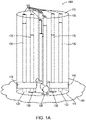
- Fig. 1A is an isometric view of an exemplary antenna 100A in accordance with an illustrative embodiment of the present invention.
- the exemplary antenna 100A comprises of a substrate 105 having a first surface 110 and a second surface 115. While the substrate 105 of antenna 100A is shown as being substantially cylindrical in shape, it should be noted that in accordance with alternative embodiments of the present invention, the substrate 105 may have alternative shapes. Therefore, the depiction of a substantially cylindrical substrate 105 should be taken as exemplary only.
- the substrate illustratively has a high dielectric constant (e.g., 12) and a low dielectric loss (e.g., 0.001).
- the substrate is chosen so that it also resonates, thereby providing gain in a direction that a conventional monopole antenna would not have. Illustratively, this gain is directed along the axis of the antenna from the second surface to the first surface.
- One exemplary substrate is the PREPERM ® PPE1200 material available from Premix Oy of Rajamaki, Finland.
- Another illustrative material is magnesium calcium titanate (MCT) series (MCT-30) material from Skyworks Solutions, Inc. of Woburn, Massachusetts.
- the substrate comprises of a polymer blended with ceramic.
- This exemplary substrate is easier to machine than conventional substrates, which simplifies manufacturing. Further, in alternative embodiments, the chosen exemplary substrate is substantially impervious to water ingress, which enables ease of use and obviates the need for a radome cover to protect the antenna.
- the substrate's second surface 115 is substantially in alignment with an exemplary ground plane 150.
- the ground plane is made of a conductive material.
- the size and shape of the ground plane 150 may be modified to tune the antenna 100 depending on the desired frequency range(s) to be utilized.
- the antenna may be mounted onto a device (not shown) that may function as a ground plane. Therefore, the description of a ground plane should be taken as exemplary only.
- a plurality of channels 120 are located within the substrate 105. In these channels 120 are located a first set of monopole elements 125 and a second set of monopole elements 130.
- a set of exemplary feed points 135 is provided that operational interconnect the antenna with a feed network (not shown).
- the first set of monopole elements 125 includes four monopole elements and are arranged so that they are approximately 90 degrees apart from each an adjacent element.
- the second set of monopole elements 130 includes four monopole elements and are also arranged so that they are approximately 90 degrees apart from the adjacent element.
- the monopoles of each set of monopoles are arranged radially around an imaginary axis extending from the second surface to the first surface.
- the feed network (not shown) can combine the feed points with equal amplitude and quadrature phase progression to produce circularly-polarized GNSS signal reception.
- the exemplary antenna 100A shown and described in connection with Fig. 1A comprises of two sets of monopoles, each set having four monopoles, and arranged as a turnstile antenna
- teachings of the present invention may be used with antennas having varying numbers of sets of monopoles.
- the number of monopoles in each set may vary.
- the monopoles may be arranged in a non-turnstile configuration. Therefore, the description of an antenna having set sets of monopoles, with four monopoles per set, arranged as a turnstile antenna should be taken as exemplary only.
- the channels 120 extend completely through the substrate, i.e., from the first surface to the second surface.
- the channels may only extend as far as necessary to fit the monopole elements 125, 130.
- the channels may extend beyond the ends of the monopole elements 125, 130, but not all the way through the substrate. Therefore, the depiction of channels 120 extending through the substrate should be taken as exemplary only.
- Each conductive path 145 is shown. Each conductive path is illustratively in a lateral channel. Each conductive path is connected to a monopole of the first set of monopoles 125 and to a monopole of the second set of monopoles 130.
- Fig. 1B is an isometric view of an exemplary antenna 100B in accordance with an illustrative embodiment of the present invention.
- Exemplary antenna 100B is generally constructed that same as antenna 100B with the addition of a conductive ring 155 that is located around the exterior of the antenna 100B.
- Exemplary conductive ring illustratively extends from the ground plane 150 to just above the height of the conductive paths 145. It should be noted that this height is exemplary only and in alternative embodiments, differing heights may be utilized.
- the conductive ring 155 provides capacitive coupling between the conductive ring 155 and the conductive paths 145. This addition may improve the antenna's gain by approximately 3dB.
- Air gaps 165 ( Fig. 2B ) may be used to determine the capacitance. By adjusting the size of the air gaps 165, the increase capacitive coupling from the conductor 145 and the conductive ring 165 may reduce the size of the antenna 100B. Further, an improved impedance match may be obtained.
- FIG. 1C is an isometric view of an exemplary antenna 100C in accordance with an illustrative embodiment of the present invention.
- Antenna 100C includes a metal top 160 that is located at the top of the antenna.
- the addition of the metal top 160 serves to narrow the bandwidth of the antenna and enables the antenna to be made shorter.
- the addition of the metal top 160 works to tune the longest of the sets of monopole elements 125, 130.
- the narrowing of the bandwidth enables a high gain and/or a smaller physical form factor for the antenna, which is advantageous for size constrained applications, e.g., in a hand-held device.
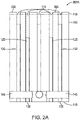
- Fig. 2A is a side cross-sectional view 200A of an exemplary antenna in accordance with an illustrative embodiment of the present invention.
- exemplary channels 120 extend from the first surface 110 to the second surface 115 of the antenna.
- a conductive layer 205 may be placed on the first surface 110.
- the conductive layer 205 may be utilized to provide an additional frequency of operation to the antenna.
- the first and second monopole elements may operate at two GNSS frequencies, while the conductive layer 205 operates as a Wi-Fi frequency.
- Another example would be the first and second sets of monopoles being resonant on two GNSS frequencies, while the conductive layer 205 being resonant in the C-band. This enables further miniaturization of antennas for use in, e.g., handheld devices.
- Fig. 2B is a side cross-sectional view 200B of an exemplary antenna in accordance with an illustrative embodiment of the present invention.
- Antenna 200B illustrates the exemplary air gaps 165 and conductive ring 155.
- the addition of the conductive ring 155 provides capacitance coupling between the conductive ring 155 and the conductors 145, which may reduce the size of antenna 200B and/or provide additional gain.
- Fig. 2C is a side cross-sectional view 200C of an exemplary antenna in accordance with an illustrative embodiment of the present invention.
- View 200C illustrates air gaps 165 at the end of the conductive paths 145.
- the conductive paths 145 may be utilized to tune the antenna.
- the conductive paths may be made of conductive adhesives or machined metal parts. Regardless of the construction, the length and/or diameter of the conductive paths 145 may be altered to tune the resonant frequencies of the antenna. This tuning technique enables simplified manufacturing.
- the monopole elements can remain at predetermined lengths, while the conductive paths 145 are altered to tune the antenna for variations in the substrate 105 permittivity.
- Fig. 2D is a side cross-sectional view 200D of an exemplary antenna in accordance with an illustrative embodiment of the present invention.
- View 200D illustrates an exemplary antenna that includes a metalized ring 230 at the top end of the antenna.
- the metalized ring 230 begins at the first surface 110 and extends along the sidewall of the antenna a short distance.
- This metalized ring may be used to reduce the overall height of the antenna.
- the metalized ring may extend approximately 0.1-0.2 inches along the antenna. However, it is expressly contemplated that it may extend other distances. Therefore, the description of 0.1-0.2 inches should be taken as exemplary only.
- the metallized ring 230 narrows the bandwidth of the antenna and allows its height to be shortened, which may be advantageous in size constrained applications. While the metal top 160 primarily tunes the longest of the sets of monopole elements 125, 130, the metallized ring 230 predominately tunes the second set of monopole elements 130.
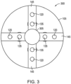
- Fig. 3 is a bottom view 300 of an exemplary antenna in accordance with an illustrative embodiment of the present invention. View 300 is exemplary taken from the viewpoint of the second surface. Exemplary channels 120 are shown along with feed points 135. The conductive paths 145 are shown.
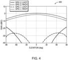
- Fig. 4 is an exemplary graph 400 illustrating gain versus elevation angle in accordance with an illustrative embodiment of the present invention.
- Exemplary graph 400 illustrates performance of an antenna constructed in accordance with the teachings contained herein and operating on two GNSS (GPS) frequencies. Notably, the antenna exhibits gain at the zenith, wherein conventional monopole turnstile antennas do not.
- GPS GNSS
- FIG. 5 is a perspective view 500 of an exemplary log periodic monopole array in accordance with an illustrative embodiment of the present invention.
- View 500 illustrates one exemplary technique for expanding the teachings of the present invention to use with more than two sets of monopoles.
- six monopole elements 510A-G are arranged on, e.g., a printed circuit board 505 as a log-periodic monopole array (LPMA).
- LPMA log-periodic monopole array
- a conductive path 515 can be located on a second surface to enable feeding of the LPMA.
- Fig. 6 is a perspective view 600 of an exemplary antenna comprising of a plurality of LPMAs 505 in accordance with an illustrative embodiment of the present invention.
- twelve LPMAs 505 have been arranged and then encapsulated in a substrate 505.
Landscapes
- Engineering & Computer Science (AREA)
- Computer Networks & Wireless Communication (AREA)
- Details Of Aerials (AREA)
Applications Claiming Priority (2)
| Application Number | Priority Date | Filing Date | Title |
|---|---|---|---|
| US202063082028P | 2020-09-23 | 2020-09-23 | |
| US17/402,795 US11824266B2 (en) | 2020-09-23 | 2021-08-16 | Encapsulated multi-band monopole antenna |
Publications (2)
| Publication Number | Publication Date |
|---|---|
| EP4131652A1 true EP4131652A1 (de) | 2023-02-08 |
| EP4131652B1 EP4131652B1 (de) | 2026-02-25 |
Family
ID=80741773
Family Applications (1)
| Application Number | Title | Priority Date | Filing Date |
|---|---|---|---|
| EP21194927.6A Active EP4131652B1 (de) | 2020-09-23 | 2021-09-03 | Gekapselte multiband-monopolantenne |
Country Status (2)
| Country | Link |
|---|---|
| US (1) | US11824266B2 (de) |
| EP (1) | EP4131652B1 (de) |
Families Citing this family (1)
| Publication number | Priority date | Publication date | Assignee | Title |
|---|---|---|---|---|
| CN113708065B (zh) * | 2020-05-21 | 2023-03-10 | 华为技术有限公司 | 一种准全向天线及信号收发设备 |
Citations (3)
| Publication number | Priority date | Publication date | Assignee | Title |
|---|---|---|---|---|
| US20030016176A1 (en) * | 1999-10-29 | 2003-01-23 | Kingsley Simon P. | Steerable-beam multiple-feed dielectric resonator antenna |
| US20030117318A1 (en) * | 2000-07-18 | 2003-06-26 | Champlain Brian De | Single receiver wireless tracking system |
| WO2020171864A2 (en) * | 2018-11-29 | 2020-08-27 | Smartsky Networks LLC | Monopole antenna assembly with directive-reflective control |
Family Cites Families (21)
| Publication number | Priority date | Publication date | Assignee | Title |
|---|---|---|---|---|
| NL61197C (de) | 1940-10-17 | |||
| US6288682B1 (en) * | 1996-03-14 | 2001-09-11 | Griffith University | Directional antenna assembly |
| US6094178A (en) | 1997-11-14 | 2000-07-25 | Ericsson, Inc. | Dual mode quadrifilar helix antenna and associated methods of operation |
| US6356242B1 (en) | 2000-01-27 | 2002-03-12 | George Ploussios | Crossed bent monopole doublets |
| US6342867B1 (en) | 2000-03-31 | 2002-01-29 | Navcom Technology, Inc. | Nested turnstile antenna |
| JP2002111354A (ja) | 2000-09-27 | 2002-04-12 | Mitsumi Electric Co Ltd | モノポールアンテナ |
| US20040017327A1 (en) | 2002-07-26 | 2004-01-29 | Andrew Corporation | Dual polarized integrated antenna |
| US6819291B1 (en) | 2003-06-02 | 2004-11-16 | Raymond J. Lackey | Reduced-size GPS antennas for anti-jam adaptive processing |
| US7444734B2 (en) | 2003-12-09 | 2008-11-04 | International Business Machines Corporation | Apparatus and methods for constructing antennas using vias as radiating elements formed in a substrate |
| FR2867617B1 (fr) * | 2004-03-10 | 2006-06-09 | Adventen | Dispositif de perturbation de la propagation d'ondes electromagnetiques, procede de fabrication et application correspondants |
| US7271769B2 (en) | 2004-09-22 | 2007-09-18 | Lenovo (Singapore) Pte Ltd. | Antennas encapsulated within plastic display covers of computing devices |
| US7570219B1 (en) * | 2006-05-16 | 2009-08-04 | Rockwell Collins, Inc. | Circular polarization antenna for precision guided munitions |
| US20080129617A1 (en) * | 2006-12-04 | 2008-06-05 | Agc Automotive Americas R&D, Inc. | Wideband Dielectric Antenna |
| US8049667B2 (en) | 2009-02-18 | 2011-11-01 | Bae Systems Information And Electronic Systems Integration Inc. | GPS antenna array and system for adaptively suppressing multiple interfering signals in azimuth and elevation |
| US8456375B2 (en) * | 2009-05-05 | 2013-06-04 | Sarantel Limited | Multifilar antenna |
| US9614293B2 (en) | 2012-10-17 | 2017-04-04 | The Mitre Corporation | Multi-band helical antenna system |
| US9246222B2 (en) | 2013-03-15 | 2016-01-26 | Tyco Electronics Corporation | Compact wideband patch antenna |
| GB201314293D0 (en) * | 2013-08-09 | 2013-09-25 | Orban Mircowave Products Nv | Dual inverted l-antenna for use as a base station antenna |
| US9941595B2 (en) | 2015-08-12 | 2018-04-10 | Novatel Inc. | Patch antenna with peripheral parasitic monopole circular arrays |
| US10935687B2 (en) * | 2016-02-23 | 2021-03-02 | Halliburton Energy Services, Inc. | Formation imaging with electronic beam steering |
| US11050144B1 (en) * | 2020-05-08 | 2021-06-29 | W. L. Gore & Associates, Inc. | Assembly with at least one antenna and a thermal insulation component |
-
2021
- 2021-08-16 US US17/402,795 patent/US11824266B2/en active Active
- 2021-09-03 EP EP21194927.6A patent/EP4131652B1/de active Active
Patent Citations (3)
| Publication number | Priority date | Publication date | Assignee | Title |
|---|---|---|---|---|
| US20030016176A1 (en) * | 1999-10-29 | 2003-01-23 | Kingsley Simon P. | Steerable-beam multiple-feed dielectric resonator antenna |
| US20030117318A1 (en) * | 2000-07-18 | 2003-06-26 | Champlain Brian De | Single receiver wireless tracking system |
| WO2020171864A2 (en) * | 2018-11-29 | 2020-08-27 | Smartsky Networks LLC | Monopole antenna assembly with directive-reflective control |
Also Published As
| Publication number | Publication date |
|---|---|
| US11824266B2 (en) | 2023-11-21 |
| US20220094076A1 (en) | 2022-03-24 |
| EP4131652B1 (de) | 2026-02-25 |
Similar Documents
| Publication | Publication Date | Title |
|---|---|---|
| US6147647A (en) | Circularly polarized dielectric resonator antenna | |
| US20060232493A1 (en) | Circular-polarization dipole helical antenna | |
| US6424300B1 (en) | Notch antennas and wireless communicators incorporating same | |
| US6292141B1 (en) | Dielectric-patch resonator antenna | |
| US7339542B2 (en) | Ultra-broadband antenna system combining an asymmetrical dipole and a biconical dipole to form a monopole | |
| US6429819B1 (en) | Dual band patch bowtie slot antenna structure | |
| US5606332A (en) | Dual function antenna structure and a portable radio having same | |
| AU2021216594A1 (en) | Antenna system for circularly polarized signals | |
| US20030103008A1 (en) | In-building low profile antenna | |
| CN107611606B (zh) | 天线结构和终端 | |
| US20020047802A1 (en) | Patch antenna device | |
| US20020000935A1 (en) | Miniaturized radio frequency antenna | |
| EP4131652B1 (de) | Gekapselte multiband-monopolantenne | |
| WO2009022767A1 (en) | An antenna integrated on a circuit board | |
| US6914567B2 (en) | Broadband combination meanderline and patch antenna | |
| KR20220153791A (ko) | 위성신호 수신용 안테나 장치 | |
| WO2026087936A1 (en) | High-performance circular polarization in a compact antenna design | |
| KR102701859B1 (ko) | 다중 gps 위성신호 주파수를 동시에 수신하는 소형 경량화 안테나 | |
| US12100900B2 (en) | Integrated 5G and GNSS compact antenna system | |
| Wang et al. | A miniaturized multi-functional antenna with UHF and CP performance for communication and navigation system | |
| Sakamoto et al. | Low-Profile Wideband GNSS Antenna with Enhanced Front-to-Back-Ratio Without Additional Ground Plane | |
| KR100841938B1 (ko) | 헬릭스 슬롯 안테나 | |
| KR100581442B1 (ko) | 휴대 무선통신 장치용 안테나부 | |
| TWM681851U (zh) | Gnss多頻段寬頻圓極化天線 | |
| KR20040080161A (ko) | 원형 편파 마이크로스트립 링 구조 안테나 |
Legal Events
| Date | Code | Title | Description |
|---|---|---|---|
| PUAI | Public reference made under article 153(3) epc to a published international application that has entered the european phase |
Free format text: ORIGINAL CODE: 0009012 |
|
| STAA | Information on the status of an ep patent application or granted ep patent |
Free format text: STATUS: THE APPLICATION HAS BEEN PUBLISHED |
|
| AK | Designated contracting states |
Kind code of ref document: A1 Designated state(s): AL AT BE BG CH CY CZ DE DK EE ES FI FR GB GR HR HU IE IS IT LI LT LU LV MC MK MT NL NO PL PT RO RS SE SI SK SM TR |
|
| RAP1 | Party data changed (applicant data changed or rights of an application transferred) |
Owner name: ANTCOM CORPORATION |
|
| STAA | Information on the status of an ep patent application or granted ep patent |
Free format text: STATUS: REQUEST FOR EXAMINATION WAS MADE |
|
| 17P | Request for examination filed |
Effective date: 20230801 |
|
| RBV | Designated contracting states (corrected) |
Designated state(s): AL AT BE BG CH CY CZ DE DK EE ES FI FR GB GR HR HU IE IS IT LI LT LU LV MC MK MT NL NO PL PT RO RS SE SI SK SM TR |
|
| GRAP | Despatch of communication of intention to grant a patent |
Free format text: ORIGINAL CODE: EPIDOSNIGR1 |
|
| STAA | Information on the status of an ep patent application or granted ep patent |
Free format text: STATUS: GRANT OF PATENT IS INTENDED |
|
| RIC1 | Information provided on ipc code assigned before grant |
Ipc: H01Q 9/04 20060101AFI20250902BHEP Ipc: H01Q 9/32 20060101ALI20250902BHEP Ipc: H01Q 21/20 20060101ALI20250902BHEP Ipc: H01Q 1/22 20060101ALI20250902BHEP Ipc: H01Q 1/40 20060101ALI20250902BHEP Ipc: H01Q 21/28 20060101ALI20250902BHEP |
|
| INTG | Intention to grant announced |
Effective date: 20250929 |
|
| GRAS | Grant fee paid |
Free format text: ORIGINAL CODE: EPIDOSNIGR3 |
|
| GRAA | (expected) grant |
Free format text: ORIGINAL CODE: 0009210 |
|
| STAA | Information on the status of an ep patent application or granted ep patent |
Free format text: STATUS: THE PATENT HAS BEEN GRANTED |
|
| AK | Designated contracting states |
Kind code of ref document: B1 Designated state(s): AL AT BE BG CH CY CZ DE DK EE ES FI FR GB GR HR HU IE IS IT LI LT LU LV MC MK MT NL NO PL PT RO RS SE SI SK SM TR |
|
| REG | Reference to a national code |
Ref country code: CH Ref legal event code: F10 Free format text: ST27 STATUS EVENT CODE: U-0-0-F10-F00 (AS PROVIDED BY THE NATIONAL OFFICE) Effective date: 20260225 Ref country code: GB Ref legal event code: FG4D |
|
| REG | Reference to a national code |
Ref country code: DE Ref legal event code: R096 Ref document number: 602021048570 Country of ref document: DE |
|
| REG | Reference to a national code |
Ref country code: IE Ref legal event code: FG4D |