EP4131664A1 - Boîte de jonction d'onduleur - Google Patents
Boîte de jonction d'onduleur Download PDFInfo
- Publication number
- EP4131664A1 EP4131664A1 EP21816718.7A EP21816718A EP4131664A1 EP 4131664 A1 EP4131664 A1 EP 4131664A1 EP 21816718 A EP21816718 A EP 21816718A EP 4131664 A1 EP4131664 A1 EP 4131664A1
- Authority
- EP
- European Patent Office
- Prior art keywords
- casing
- inverter
- junction box
- box according
- cover plate
- Prior art date
- Legal status (The legal status is an assumption and is not a legal conclusion. Google has not performed a legal analysis and makes no representation as to the accuracy of the status listed.)
- Granted
Links
Images


Classifications
-
- H—ELECTRICITY
- H05—ELECTRIC TECHNIQUES NOT OTHERWISE PROVIDED FOR
- H05K—PRINTED CIRCUITS; CASINGS OR CONSTRUCTIONAL DETAILS OF ELECTRIC APPARATUS; MANUFACTURE OF ASSEMBLAGES OF ELECTRICAL COMPONENTS
- H05K5/00—Casings, cabinets or drawers for electric apparatus
- H05K5/02—Details
- H05K5/0247—Electrical details of casings, e.g. terminals, passages for cables or wiring
-
- H—ELECTRICITY
- H02—GENERATION; CONVERSION OR DISTRIBUTION OF ELECTRIC POWER
- H02G—INSTALLATION OF ELECTRIC CABLES OR LINES, OR OF COMBINED OPTICAL AND ELECTRIC CABLES OR LINES
- H02G3/00—Installations of electric cables or lines or protective tubing therefor in or on buildings, equivalent structures or vehicles
- H02G3/02—Details
- H02G3/08—Distribution boxes; Connection or junction boxes
- H02G3/081—Bases, casings or covers
- H02G3/083—Inlets
- H02G3/085—Inlets including knock-out or tear-out sections
-
- B—PERFORMING OPERATIONS; TRANSPORTING
- B60—VEHICLES IN GENERAL
- B60R—VEHICLES, VEHICLE FITTINGS, OR VEHICLE PARTS, NOT OTHERWISE PROVIDED FOR
- B60R16/00—Electric or fluid circuits specially adapted for vehicles and not otherwise provided for; Arrangement of elements of electric or fluid circuits specially adapted for vehicles and not otherwise provided for
- B60R16/02—Electric or fluid circuits specially adapted for vehicles and not otherwise provided for; Arrangement of elements of electric or fluid circuits specially adapted for vehicles and not otherwise provided for electric constitutive elements
- B60R16/023—Electric or fluid circuits specially adapted for vehicles and not otherwise provided for; Arrangement of elements of electric or fluid circuits specially adapted for vehicles and not otherwise provided for electric constitutive elements for transmission of signals between vehicle parts or subsystems
- B60R16/0238—Electrical distribution centers
-
- H—ELECTRICITY
- H01—ELECTRIC ELEMENTS
- H01R—ELECTRICALLY-CONDUCTIVE CONNECTIONS; STRUCTURAL ASSOCIATIONS OF A PLURALITY OF MUTUALLY-INSULATED ELECTRICAL CONNECTING ELEMENTS; COUPLING DEVICES; CURRENT COLLECTORS
- H01R13/00—Details of coupling devices of the kinds covered by groups H01R12/70 or H01R24/00 - H01R33/00
- H01R13/66—Structural association with built-in electrical component
- H01R13/70—Structural association with built-in electrical component with built-in switch
- H01R13/713—Structural association with built-in electrical component with built-in switch the switch being a safety switch
-
- H—ELECTRICITY
- H01—ELECTRIC ELEMENTS
- H01R—ELECTRICALLY-CONDUCTIVE CONNECTIONS; STRUCTURAL ASSOCIATIONS OF A PLURALITY OF MUTUALLY-INSULATED ELECTRICAL CONNECTING ELEMENTS; COUPLING DEVICES; CURRENT COLLECTORS
- H01R9/00—Structural associations of a plurality of mutually-insulated electrical connecting elements, e.g. terminal strips or terminal blocks; Terminals or binding posts mounted upon a base or in a case; Bases therefor
- H01R9/22—Bases, e.g. strip, block, panel
- H01R9/24—Terminal blocks
-
- H—ELECTRICITY
- H02—GENERATION; CONVERSION OR DISTRIBUTION OF ELECTRIC POWER
- H02M—APPARATUS FOR CONVERSION BETWEEN AC AND AC, BETWEEN AC AND DC, OR BETWEEN DC AND DC, AND FOR USE WITH MAINS OR SIMILAR POWER SUPPLY SYSTEMS; CONVERSION OF DC OR AC INPUT POWER INTO SURGE OUTPUT POWER; CONTROL OR REGULATION THEREOF
- H02M7/00—Conversion of AC power input into DC power output; Conversion of DC power input into AC power output
- H02M7/003—Constructional details, e.g. physical layout, assembly, wiring or busbar connections
Definitions
- the present disclosure relates to the technical field of wire connection, and more particularly, to an inverter junction box.
- junction box which can not only meet the multi-directional wiring requirements, but also realize the high-voltage protection function.
- the present disclosure proposes an inverter junction box to solve or partially solve the above problems.
- the present disclosure provides an inverter junction box.
- the inverter junction box comprises a casing, a cover plate and a knockout pin, wherein
- the inverter junction box further comprises a high-voltage busbar terminal; wherein the high-voltage busbar terminal comprises an insulating body and two conductive columns, and the conductive columns are respectively inserted in the insulating body.
- the conductive column is made of copper.
- a through hole is provided in a central part of the conductive column, and the high-voltage busbar terminal can be connected to the incoming terminal of the inverter via the through hole and a bolt.
- the casing is further provided therein with a positioning plate for fixing the insulating body and the knockout pin at a middle position of the casing.
- the casing has a cylindrical shape or a regular quadrangular prism shape as a whole
- the insulation body extends along a diameter of the cylindrical shape or a diagonal of the regular quadrangular prism shape with two ends abutting against the casing, and the two conductive columns are symmetrically provided on the diameter or the diagonal.
- outer end sides of the high-voltage busbar terminal are provided with a number of insulating medium support protrusions.
- connecting part and the casing are arranged to be perpendicular to each other, the connecting part is provided therein with a positive connecting hole and a negative connecting hole, and the positive connecting hole and the negative connecting hole are communicated with an interior of the casing.
- the casing is provided thereon with a number of longitudinally penetrating installation holes, and the cover plate is also provided with installation holes at corresponding positions.
- the casing is provided thereon with a positioning hole engaging with a positioning column on the inverter, or the casing is provided with a positioning column engaging with a positioning hole on the inverter.
- the above inverter junction box has the following advantages.
- the knockout pin cooperates with the protection device on the inverter, which can realize the high-voltage protection when opening the cover plate of the junction box to perform wire connection, and effectively ensure the safety of operator and equipment.
- the wire connecting direction of the junction box can be changed by providing the connecting part with a different orientation or by rotating the casing during installation to change the orientation of connecting part.
- An embodiment of the present disclosure provides an inverter junction box.
- the junction box in the present disclosure may also be used in other similar scenarios, which is not limited to the terminal connection of the inverter.
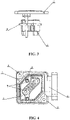
- the inverter junction box comprises casing 1, cover plate 2 and knockout pin 4.
- the cover plate 2 is detachably connected with the top part of casing 1.
- One end of the knockout pin 4 is detachably connected to the bottom part of the cover plate 2, and the other end abuts against a protection device on the inverter.
- the knockout pin 4 may be connected and fixed with the cover plate 2 by screws. When the knockout pin 4 abuts against the protective device, the high-voltage protection will not be triggered.
- One side of the casing 1 is equipped with a connecting part, and the external cables can be connected with the interior of the junction box via the connecting part.
- the bottom part of the casing 1 is a hollow structure, and abuts against the incoming terminal of the inverter.
- the design of the hollow structure facilitates the connection between the internal structure of the junction box and the inverter.
- the inverter junction box further comprises a high voltage busbar terminal 3.
- the high voltage busbar terminal 3 comprises an insulating body and two conductive columns 7, and the conductive columns 7 are respectively inserted in the insulating body.
- One end of the conductive column 7 is connected with the external cable, and the other end is connected with the incoming terminal of the inverter. Its function is to realize the connection between the external cable and the inverter device.
- the design of the insulation body can realize the relative fixation of the two conductive columns 7.
- the insulation body part between the two conductive columns 7 may be a hollow structure, which facilitates heat dissipation and material saving.
- the design of the high-voltage busbar terminal 3 can realize the connection between the inverter device and external cables of different directions, so that the high-voltage harness of external cables is not restricted by the whole vehicle structure, and meet the requirements of multi-directional wiring of the inverter.
- the connection structure between the inverter device and the junction box shown in FIG. 6 does not use the high-voltage busbar terminal 3, and the external cable is directly connected with the inverter terminal after entering the connection box.
- the connection structure shown in FIG. 5 uses the high-voltage busbar terminal 3, the change of the wire connecting direction of the inverter device is realized, and the junction box can also realize other wire connecting directions of the inverter device.
- the conductive column 7 is made of copper.
- the conductive column 7 may also be made of other metal materials with excellent conductivity.
- a central part of the conductive column 7 on the high-voltage busbar terminal 3 is provided with a through hole.
- the conductive column 7 is fixed on the incoming terminal of the inverter via the through hole and a bolt, so as to realize the electrical conductivity between the conductive column 7 and the incoming terminal, and the external cable is also fixedly connected with the conductive column 7 via the bolt.
- a positioning plate is further provided in the casing 1. Holes are opened on the positioning plate at positions corresponding to the insulating body and knockout pin 4, and the insulating body and knockout pin 4 can pass through the holes.
- the positioning plate is used to fix the insulating body and knockout pin 4 at a middle position of the casing 1 to prevent the insulating body and knockout pin 4 from shaking in the casing 1.
- the casing 1 has a cylindrical shape or a regular quadrangular prism shape as a whole.
- the casing 1 may be designed into other shapes as required, such as a rectangle.
- the insulating body extends along the diameter of the cylinder or the diagonal of the regular quadrangular prism, and abuts against the casing.
- the two conductive columns 7 are symmetrically disposed on the diameter or the diagonal. This structure makes the insulating body more firmly fixed in the casing, and also effectively reduces the volume of the casing 1 and makes the junction box smaller as a whole.
- the outer end sides of the high-voltage busbar terminal 3 are provided with a number of insulating medium support protrusions, which respectively abut against the inner wall of the casing 1 to limit the position of the high-voltage busbar terminal 3 and fix it.
- the connecting part is perpendicular to the casing 1.
- they can be arranged in an L-shape.
- a notch is provided at a corner of the casing 1 below the connecting part. The design of the notch can save material and reduce weight.
- a positive connecting hole and a negative connecting hole are provided in the connecting part, and the positive connecting hole and the negative connecting hole are communicated with the interior of the casing.
- the positive and negative poles of the external cable may pass through the positive and negative connecting holes respectively to connect with the conductive columns 7 or the incoming terminals of the inverter.
- the casing 1 is provided with a number of longitudinally penetrating installation holes 6,
- the cover plate 2 is also provided with installation holes 6 at corresponding positions, and the position of the installation holes 6 on the casing 1 are consistent with the position of the installation holes 6 on the cover plate 2. Screws or bolts pass through the installation holes 6 to realize the fixation between the cover plate 2 and the casing 1, as well as the fixation between the casing 1 and the inverter device.
- the casing 1 is provided with a positioning hole 5 that engages with a positioning column on the inverter.
- the positioning hole 5 may completely penetrate the casing 1. Through the engagement of the positioning hole and the positioning column, the position of the casing 1 can be fixed. Of course, the positions of the positioning hole and the positioning column may also be interchanged.
- the present disclosure discloses an inverter junction box.
- the inverter junction box comprises a casing, a cover plate and a knockout pin.
- One end of the knockout pin is detachably connected to the bottom part of the cover plate, and the other end abuts against the protective device on the inverter.
- One side of the casing is provided with a connecting part, and the bottom part of the casing is a hollow structure.
- the knockout pin cooperates with the protection device on the inverter, which can realize the high-voltage protection when opening the cover plate of the junction box to perform wire connection, and effectively ensure the safety of operator and equipment.
- a junction box according to an embodiment of the present disclosure by providing a high-voltage busbar terminal, the connection between the inverter and cables of different directions can be realized, and the requirements of multi-directional wiring of the inverter can be met.
Landscapes
- Engineering & Computer Science (AREA)
- Architecture (AREA)
- Civil Engineering (AREA)
- Structural Engineering (AREA)
- Power Engineering (AREA)
- Mechanical Engineering (AREA)
- Microelectronics & Electronic Packaging (AREA)
- Patch Boards (AREA)
- Connection Or Junction Boxes (AREA)
Applications Claiming Priority (2)
| Application Number | Priority Date | Filing Date | Title |
|---|---|---|---|
| CN202020979078.3U CN212435595U (zh) | 2020-06-02 | 2020-06-02 | 一种逆变器接线盒 |
| PCT/CN2021/075551 WO2021244062A1 (fr) | 2020-06-02 | 2021-02-05 | Boîte de jonction d'onduleur |
Publications (3)
| Publication Number | Publication Date |
|---|---|
| EP4131664A1 true EP4131664A1 (fr) | 2023-02-08 |
| EP4131664A4 EP4131664A4 (fr) | 2023-11-08 |
| EP4131664B1 EP4131664B1 (fr) | 2025-04-16 |
Family
ID=74270097
Family Applications (1)
| Application Number | Title | Priority Date | Filing Date |
|---|---|---|---|
| EP21816718.7A Active EP4131664B1 (fr) | 2020-06-02 | 2021-02-05 | Boîte de jonction d'onduleur |
Country Status (4)
| Country | Link |
|---|---|
| US (1) | US12266911B2 (fr) |
| EP (1) | EP4131664B1 (fr) |
| CN (1) | CN212435595U (fr) |
| WO (1) | WO2021244062A1 (fr) |
Families Citing this family (2)
| Publication number | Priority date | Publication date | Assignee | Title |
|---|---|---|---|---|
| CN212435595U (zh) | 2020-06-02 | 2021-01-29 | 精进电动科技股份有限公司 | 一种逆变器接线盒 |
| CN115334812A (zh) * | 2022-08-23 | 2022-11-11 | 智新科技股份有限公司 | 一种电机控制器上盖板及壳体 |
Family Cites Families (16)
| Publication number | Priority date | Publication date | Assignee | Title |
|---|---|---|---|---|
| JPS62132619U (fr) | 1986-02-17 | 1987-08-21 | ||
| ATE92191T1 (de) * | 1987-03-31 | 1993-08-15 | Siemens Ag | Vorrichtung fuer die elektrische funktionspruefung von verdrahtungsfeldern, insbesondere von leiterplatten. |
| CN2264389Y (zh) * | 1995-12-06 | 1997-10-08 | 林宏文 | 红外线光电感应器之改良结构 |
| JP2008218094A (ja) * | 2007-03-01 | 2008-09-18 | Toyota Motor Corp | 接続装置 |
| CN101913328A (zh) * | 2010-07-29 | 2010-12-15 | 重庆长安汽车股份有限公司 | 一种纯电动汽车的驱动电机控制器接线盒 |
| JP5725996B2 (ja) * | 2011-06-21 | 2015-05-27 | 矢崎総業株式会社 | コネクタ |
| CN202169876U (zh) * | 2011-07-22 | 2012-03-21 | 北京航空航天大学 | 一种用于电动汽车的高压保护装置 |
| JP6014436B2 (ja) * | 2012-09-20 | 2016-10-25 | 株式会社小松製作所 | インバータ |
| JP6034665B2 (ja) * | 2012-11-05 | 2016-11-30 | 矢崎総業株式会社 | 電気接続箱 |
| JP6299898B1 (ja) * | 2017-02-21 | 2018-03-28 | 株式会社オートネットワーク技術研究所 | 接続モジュール |
| CN109070754B (zh) * | 2017-03-24 | 2022-07-22 | 法雷奥西门子新能源汽车(深圳)有限公司 | 电气设备及其组装方法 |
| KR102150679B1 (ko) * | 2018-03-13 | 2020-09-01 | 주식회사 엘지화학 | 배터리 모듈, 이러한 배터리 모듈을 포함하는 배터리 팩 및 이러한 배터리 팩을 포함하는 자동차 |
| KR102469872B1 (ko) * | 2019-04-15 | 2022-11-23 | 에스케이온 주식회사 | 배터리 모듈 |
| CN110829100A (zh) * | 2019-12-02 | 2020-02-21 | 苏州智绿环保科技有限公司 | 换电连接器 |
| CN212435595U (zh) * | 2020-06-02 | 2021-01-29 | 精进电动科技股份有限公司 | 一种逆变器接线盒 |
| CN212436067U (zh) * | 2020-06-02 | 2021-01-29 | 精进电动科技股份有限公司 | 一种逆变器壳体以及逆变器与接线盒的连接结构 |
-
2020
- 2020-06-02 CN CN202020979078.3U patent/CN212435595U/zh active Active
-
2021
- 2021-02-05 EP EP21816718.7A patent/EP4131664B1/fr active Active
- 2021-02-05 US US17/997,845 patent/US12266911B2/en active Active
- 2021-02-05 WO PCT/CN2021/075551 patent/WO2021244062A1/fr not_active Ceased
Also Published As
| Publication number | Publication date |
|---|---|
| US20230170680A1 (en) | 2023-06-01 |
| CN212435595U (zh) | 2021-01-29 |
| EP4131664A4 (fr) | 2023-11-08 |
| WO2021244062A1 (fr) | 2021-12-09 |
| US12266911B2 (en) | 2025-04-01 |
| EP4131664B1 (fr) | 2025-04-16 |
Similar Documents
| Publication | Publication Date | Title |
|---|---|---|
| US4079439A (en) | Loadcenter having a dual purpose neutral rail | |
| KR102803859B1 (ko) | 모듈 출력극 구조 | |
| US12266911B2 (en) | Inverter junction box | |
| JP5931778B2 (ja) | 電力変換モジュール結線用のバスバーアッセンブリ | |
| US11735999B2 (en) | Inverter housing and connecting structure for inverter and junction box | |
| CN107706013A (zh) | 手动维护开关 | |
| CN209344964U (zh) | 一种新能源车用水冷电机系统 | |
| CN214589484U (zh) | 一种安全可靠的高压大电流接线盒 | |
| TWM639338U (zh) | 電力收發裝置及其電連接器 | |
| CN111769377B (zh) | 一种接线盒 | |
| CN218525773U (zh) | 电力收发装置及其电连接器 | |
| JP2897633B2 (ja) | 電気自動車用高圧大電流分電装置 | |
| CN115173722B (zh) | 一种电源盒、滤波组件及混合动力车辆 | |
| CN215989270U (zh) | 动力线连接器 | |
| JPH0721050Y2 (ja) | 配電装置 | |
| EP4567855A1 (fr) | Module de fusible de goujon à sauter | |
| CN222463956U (zh) | 一种三相绝缘模组及电气设备 | |
| CN223261226U (zh) | 高压输变电系统及其高压母线桥总成 | |
| CN213879062U (zh) | 气体绝缘金属封闭开关模块及其终端封闭组件 | |
| CN220963190U (zh) | 断路器 | |
| CN214900555U (zh) | 一种带有集成开关的电机 | |
| JPS59104198A (ja) | 気密端子 | |
| CN110120642B (zh) | 一种套管接线装置及输电设备 | |
| JP2017204917A (ja) | 電力変換装置 | |
| WO2026045957A1 (fr) | Unité de distribution d'énergie de batterie et batterie d'alimentation |
Legal Events
| Date | Code | Title | Description |
|---|---|---|---|
| STAA | Information on the status of an ep patent application or granted ep patent |
Free format text: STATUS: THE INTERNATIONAL PUBLICATION HAS BEEN MADE |
|
| PUAI | Public reference made under article 153(3) epc to a published international application that has entered the european phase |
Free format text: ORIGINAL CODE: 0009012 |
|
| STAA | Information on the status of an ep patent application or granted ep patent |
Free format text: STATUS: REQUEST FOR EXAMINATION WAS MADE |
|
| 17P | Request for examination filed |
Effective date: 20221103 |
|
| AK | Designated contracting states |
Kind code of ref document: A1 Designated state(s): AL AT BE BG CH CY CZ DE DK EE ES FI FR GB GR HR HU IE IS IT LI LT LU LV MC MK MT NL NO PL PT RO RS SE SI SK SM TR |
|
| DAV | Request for validation of the european patent (deleted) | ||
| DAX | Request for extension of the european patent (deleted) | ||
| STAA | Information on the status of an ep patent application or granted ep patent |
Free format text: STATUS: EXAMINATION IS IN PROGRESS |
|
| A4 | Supplementary search report drawn up and despatched |
Effective date: 20231010 |
|
| RIC1 | Information provided on ipc code assigned before grant |
Ipc: H05K 5/02 20060101ALI20231004BHEP Ipc: B60R 16/023 20060101ALI20231004BHEP Ipc: H02M 7/00 20060101ALI20231004BHEP Ipc: H01R 13/713 20060101ALI20231004BHEP Ipc: H01R 9/24 20060101AFI20231004BHEP |
|
| 17Q | First examination report despatched |
Effective date: 20231106 |
|
| GRAP | Despatch of communication of intention to grant a patent |
Free format text: ORIGINAL CODE: EPIDOSNIGR1 |
|
| STAA | Information on the status of an ep patent application or granted ep patent |
Free format text: STATUS: GRANT OF PATENT IS INTENDED |
|
| INTG | Intention to grant announced |
Effective date: 20250108 |
|
| GRAS | Grant fee paid |
Free format text: ORIGINAL CODE: EPIDOSNIGR3 |
|
| GRAA | (expected) grant |
Free format text: ORIGINAL CODE: 0009210 |
|
| STAA | Information on the status of an ep patent application or granted ep patent |
Free format text: STATUS: THE PATENT HAS BEEN GRANTED |
|
| AK | Designated contracting states |
Kind code of ref document: B1 Designated state(s): AL AT BE BG CH CY CZ DE DK EE ES FI FR GB GR HR HU IE IS IT LI LT LU LV MC MK MT NL NO PL PT RO RS SE SI SK SM TR |
|
| P01 | Opt-out of the competence of the unified patent court (upc) registered |
Free format text: CASE NUMBER: APP_12097/2025 Effective date: 20250312 |
|
| REG | Reference to a national code |
Ref country code: GB Ref legal event code: FG4D |
|
| REG | Reference to a national code |
Ref country code: CH Ref legal event code: EP |
|
| REG | Reference to a national code |
Ref country code: IE Ref legal event code: FG4D |
|
| REG | Reference to a national code |
Ref country code: DE Ref legal event code: R096 Ref document number: 602021029338 Country of ref document: DE |
|
| REG | Reference to a national code |
Ref country code: NL Ref legal event code: MP Effective date: 20250416 |
|
| PG25 | Lapsed in a contracting state [announced via postgrant information from national office to epo] |
Ref country code: NL Free format text: LAPSE BECAUSE OF FAILURE TO SUBMIT A TRANSLATION OF THE DESCRIPTION OR TO PAY THE FEE WITHIN THE PRESCRIBED TIME-LIMIT Effective date: 20250416 |
|
| REG | Reference to a national code |
Ref country code: AT Ref legal event code: MK05 Ref document number: 1786457 Country of ref document: AT Kind code of ref document: T Effective date: 20250416 |
|
| PG25 | Lapsed in a contracting state [announced via postgrant information from national office to epo] |
Ref country code: FI Free format text: LAPSE BECAUSE OF FAILURE TO SUBMIT A TRANSLATION OF THE DESCRIPTION OR TO PAY THE FEE WITHIN THE PRESCRIBED TIME-LIMIT Effective date: 20250416 Ref country code: ES Free format text: LAPSE BECAUSE OF FAILURE TO SUBMIT A TRANSLATION OF THE DESCRIPTION OR TO PAY THE FEE WITHIN THE PRESCRIBED TIME-LIMIT Effective date: 20250416 Ref country code: PT Free format text: LAPSE BECAUSE OF FAILURE TO SUBMIT A TRANSLATION OF THE DESCRIPTION OR TO PAY THE FEE WITHIN THE PRESCRIBED TIME-LIMIT Effective date: 20250818 |
|
| REG | Reference to a national code |
Ref country code: LT Ref legal event code: MG9D |
|
| PG25 | Lapsed in a contracting state [announced via postgrant information from national office to epo] |
Ref country code: NO Free format text: LAPSE BECAUSE OF FAILURE TO SUBMIT A TRANSLATION OF THE DESCRIPTION OR TO PAY THE FEE WITHIN THE PRESCRIBED TIME-LIMIT Effective date: 20250716 Ref country code: GR Free format text: LAPSE BECAUSE OF FAILURE TO SUBMIT A TRANSLATION OF THE DESCRIPTION OR TO PAY THE FEE WITHIN THE PRESCRIBED TIME-LIMIT Effective date: 20250717 |
|
| PG25 | Lapsed in a contracting state [announced via postgrant information from national office to epo] |
Ref country code: PL Free format text: LAPSE BECAUSE OF FAILURE TO SUBMIT A TRANSLATION OF THE DESCRIPTION OR TO PAY THE FEE WITHIN THE PRESCRIBED TIME-LIMIT Effective date: 20250416 |
|
| PG25 | Lapsed in a contracting state [announced via postgrant information from national office to epo] |
Ref country code: BG Free format text: LAPSE BECAUSE OF FAILURE TO SUBMIT A TRANSLATION OF THE DESCRIPTION OR TO PAY THE FEE WITHIN THE PRESCRIBED TIME-LIMIT Effective date: 20250416 |
|
| PG25 | Lapsed in a contracting state [announced via postgrant information from national office to epo] |
Ref country code: HR Free format text: LAPSE BECAUSE OF FAILURE TO SUBMIT A TRANSLATION OF THE DESCRIPTION OR TO PAY THE FEE WITHIN THE PRESCRIBED TIME-LIMIT Effective date: 20250416 |
|
| PG25 | Lapsed in a contracting state [announced via postgrant information from national office to epo] |
Ref country code: AT Free format text: LAPSE BECAUSE OF FAILURE TO SUBMIT A TRANSLATION OF THE DESCRIPTION OR TO PAY THE FEE WITHIN THE PRESCRIBED TIME-LIMIT Effective date: 20250416 |
|
| PG25 | Lapsed in a contracting state [announced via postgrant information from national office to epo] |
Ref country code: RS Free format text: LAPSE BECAUSE OF FAILURE TO SUBMIT A TRANSLATION OF THE DESCRIPTION OR TO PAY THE FEE WITHIN THE PRESCRIBED TIME-LIMIT Effective date: 20250716 |
|
| PG25 | Lapsed in a contracting state [announced via postgrant information from national office to epo] |
Ref country code: IS Free format text: LAPSE BECAUSE OF FAILURE TO SUBMIT A TRANSLATION OF THE DESCRIPTION OR TO PAY THE FEE WITHIN THE PRESCRIBED TIME-LIMIT Effective date: 20250816 |
|
| PG25 | Lapsed in a contracting state [announced via postgrant information from national office to epo] |
Ref country code: LV Free format text: LAPSE BECAUSE OF FAILURE TO SUBMIT A TRANSLATION OF THE DESCRIPTION OR TO PAY THE FEE WITHIN THE PRESCRIBED TIME-LIMIT Effective date: 20250416 |
|
| PG25 | Lapsed in a contracting state [announced via postgrant information from national office to epo] |
Ref country code: DK Free format text: LAPSE BECAUSE OF FAILURE TO SUBMIT A TRANSLATION OF THE DESCRIPTION OR TO PAY THE FEE WITHIN THE PRESCRIBED TIME-LIMIT Effective date: 20250416 Ref country code: SM Free format text: LAPSE BECAUSE OF FAILURE TO SUBMIT A TRANSLATION OF THE DESCRIPTION OR TO PAY THE FEE WITHIN THE PRESCRIBED TIME-LIMIT Effective date: 20250416 |
|
| REG | Reference to a national code |
Ref country code: DE Ref legal event code: R097 Ref document number: 602021029338 Country of ref document: DE |
|
| PG25 | Lapsed in a contracting state [announced via postgrant information from national office to epo] |
Ref country code: CZ Free format text: LAPSE BECAUSE OF FAILURE TO SUBMIT A TRANSLATION OF THE DESCRIPTION OR TO PAY THE FEE WITHIN THE PRESCRIBED TIME-LIMIT Effective date: 20250416 |
|
| PG25 | Lapsed in a contracting state [announced via postgrant information from national office to epo] |
Ref country code: EE Free format text: LAPSE BECAUSE OF FAILURE TO SUBMIT A TRANSLATION OF THE DESCRIPTION OR TO PAY THE FEE WITHIN THE PRESCRIBED TIME-LIMIT Effective date: 20250416 |
|
| PG25 | Lapsed in a contracting state [announced via postgrant information from national office to epo] |
Ref country code: SK Free format text: LAPSE BECAUSE OF FAILURE TO SUBMIT A TRANSLATION OF THE DESCRIPTION OR TO PAY THE FEE WITHIN THE PRESCRIBED TIME-LIMIT Effective date: 20250416 |
|
| PLBE | No opposition filed within time limit |
Free format text: ORIGINAL CODE: 0009261 |
|
| STAA | Information on the status of an ep patent application or granted ep patent |
Free format text: STATUS: NO OPPOSITION FILED WITHIN TIME LIMIT |
|
| REG | Reference to a national code |
Ref country code: CH Ref legal event code: L10 Free format text: ST27 STATUS EVENT CODE: U-0-0-L10-L00 (AS PROVIDED BY THE NATIONAL OFFICE) Effective date: 20260225 |
|
| 26N | No opposition filed |
Effective date: 20260119 |
|
| PGFP | Annual fee paid to national office [announced via postgrant information from national office to epo] |
Ref country code: DE Payment date: 20260206 Year of fee payment: 6 |
|
| PGFP | Annual fee paid to national office [announced via postgrant information from national office to epo] |
Ref country code: IT Payment date: 20260209 Year of fee payment: 6 |
|
| PGFP | Annual fee paid to national office [announced via postgrant information from national office to epo] |
Ref country code: FR Payment date: 20260227 Year of fee payment: 6 |