EP4131668B1 - Prise de courant avec couvercle amovible - Google Patents
Prise de courant avec couvercle amovible Download PDFInfo
- Publication number
- EP4131668B1 EP4131668B1 EP21189931.5A EP21189931A EP4131668B1 EP 4131668 B1 EP4131668 B1 EP 4131668B1 EP 21189931 A EP21189931 A EP 21189931A EP 4131668 B1 EP4131668 B1 EP 4131668B1
- Authority
- EP
- European Patent Office
- Prior art keywords
- socket
- cover plate
- plug
- guide
- spring
- Prior art date
- Legal status (The legal status is an assumption and is not a legal conclusion. Google has not performed a legal analysis and makes no representation as to the accuracy of the status listed.)
- Active
Links
Images


Classifications
-
- H—ELECTRICITY
- H01—ELECTRIC ELEMENTS
- H01R—ELECTRICALLY-CONDUCTIVE CONNECTIONS; STRUCTURAL ASSOCIATIONS OF A PLURALITY OF MUTUALLY-INSULATED ELECTRICAL CONNECTING ELEMENTS; COUPLING DEVICES; CURRENT COLLECTORS
- H01R13/00—Details of coupling devices of the kinds covered by groups H01R12/70 or H01R24/00 - H01R33/00
- H01R13/44—Means for preventing access to live contacts
- H01R13/447—Shutter or cover plate
- H01R13/453—Shutter or cover plate opened by engagement of counterpart
- H01R13/4538—Covers sliding or withdrawing in the direction of engagement
-
- H—ELECTRICITY
- H01—ELECTRIC ELEMENTS
- H01R—ELECTRICALLY-CONDUCTIVE CONNECTIONS; STRUCTURAL ASSOCIATIONS OF A PLURALITY OF MUTUALLY-INSULATED ELECTRICAL CONNECTING ELEMENTS; COUPLING DEVICES; CURRENT COLLECTORS
- H01R13/00—Details of coupling devices of the kinds covered by groups H01R12/70 or H01R24/00 - H01R33/00
- H01R13/44—Means for preventing access to live contacts
- H01R13/447—Shutter or cover plate
- H01R13/453—Shutter or cover plate opened by engagement of counterpart
- H01R13/4532—Rotating shutter
Definitions
- the invention relates to a socket for a plug-and-socket connection, said socket being cup shaped and having a guided cover plate movable in axial direction to close the socket in a nonoperating state with no plug being connected to the socket.
- the cover plate is guided in the socket, taking a spring-loaded first position in its nonoperating state and is movable axially and/or rotatory to a second position within the socket when pushing down the plug into the socket until the pins of the plug fully engage the electrical contacts.
- Plug-and-socket connections as customarily known in the art nowadays need to satisfy safety regulations as well as aesthetic requirements concerning design and aesthetic appearance. In trying to fulfill all expectations developers often have to face a tradeoff or a conflict of design ideas.
- electrical sockets, respectively plug-and-socket connections have to be provided with safety devices, in particular relating to child-safety. It is therefore necessary to ensure that unintentional contact with voltage carrying components is prevented, notably without correctly inserting a plug into a socket.
- insertion of a plug into a socket should not be too difficult and should not require a handling, that is complicated and undue.
- an electrical socket that has a safety device comprising a shutter member with at least a pair of lugs engageable by respective pins of an electric connector plug inserted into the socket.
- a safety device comprising a shutter member with at least a pair of lugs engageable by respective pins of an electric connector plug inserted into the socket.
- the lugs In a rest position of the shutter member the lugs mask apertures of the body of the socket.
- the lugs are deflected by the contact pins of the inserted plug and the shutter member is rotatably displaced by means of inclined surfaces on the lugs.
- This device however is of complex structure and function, and requires increased force to displace the lugs by rotating the shutter member when inserting the plug into the socket.
- an electric plug safety adapter which includes a hollow tubular housing, a face plate having holes for receiving the prongs of an electric plug, and a spring.
- the face plate is moveably mounted within the housing, with the spring extending therebetween to bias the housing such that the housing extends forward of the face plate and toward an electrical outlet when the adapter is mounted to an electric plug.
- the prongs of the electric plug are inserted through the holes of the face plate to mount the plug safety adapter to the housing, with a snug fit between the face plate holes and the prongs such that the plug safety adapter will remain secured to the electric plug during normal use.
- the rear side of the face plate contacts the tip of the electrical plug case, with the housing being biased by the spring such that the housing extends forward of the face plate, fully enclosing the prongs of the electric plug therein.
- a cup shaped socket for a plug-and-socket connection has a guided cover plate movable in axial direction to close the socket in a nonoperating state, i.e., with no plug being connected to the socket.
- the cover plate is guided in the socket by guiding means and takes a spring-loaded first position in a nonoperating state.
- the cover plate as such may also comprise any subset of functional means, e.g., rotatable shutters for plug pin holes etc., which are not object of this invention.
- the first position may be defined by a design that provides an inwardly orientated protrusion at the sockets outer opening to be engaged by the cover plate in the nonoperating state, i.e., where the socket is closed by the cover plate.
- the engaging parts may also be reversed, i.e., the protrusion may be provided at or on the cover plate and may engage with corresponding structures of the socket's base part.
- the cover plate is movable axially and/or rotatory with respect to the socket and may be moved to a second position at a bottom bearing surface of the socket when pushing down the plug into the socket until the pins of the plug fully engage the electrical contacts in the socket.
- the cup shaped socket as such may have an integral base part or may be designed to build a complete cup only when inserted or connected to a separate base component, e.g., a component of a multiple socket outlet.
- the socket comprises a first guiding means to guide said cover plate while axially and/or rotatory moving down into the socket.
- This first guiding means may be provided by the peripheral surface area of said cover plate slidably interacting with the inner surface of the socket being cylindrical, i.e., corresponding to the inner circumference of the socket.
- Said peripheral surface area of the cover plate is forming a disc-like cut from a spherical profile with its diameter tapering towards the bottom of the socket.
- the slidable interaction between the spherically profiled peripheral surface area of said cover plate and the inner cylindrical surface of the socket cannot cause any stick-slip effect while the cover plate is moving down into the socket.
- the thickness of the cover plate may be very small in relation to its diameter, which approximately corresponds to the socket's inner diameter, no jamming or blocking of the cover plate can take place. Therefore, one object of the invention, i.e., to allow smooth and easy insertion of a plug, is already met by the layout of the first guiding means.
- the cut spherical shape avoids the blocking during movement and allows both, rotative and vertical sliding.
- peripheral surface area of said cover plate it is advantageous to design the peripheral surface area of said cover plate to follow a spherical profile, in particular a cut-off spherical shape.
- Tools for such a profile may be manufactured without difficulties as they can be milled quite easily by curve-guided cutting/milling machinery.
- said cover plate in its first position in the nonoperating state, is spring loaded by a helical compression spring and/or torsion spring acting between said cup shaped socket and said cover plate.
- a helical compression spring and/or torsion spring acting between said cup shaped socket and said cover plate.
- said cover plate when engaging said inwardly orientated protrusion at the sockets outer opening in its first position, said cover plate's outer or front-facing surface is essentially flush with the edge of said sockets outer opening.
- Such engagement leads to a plain outer appearance of the socket, whereby another object of the invention is achieved, i.e., an agreeable and pleasing design of the socket, when not in use.
- At least one second guiding means is provided to guide said cover plate while axially and/or rotatory moving down into the socket, said second guiding means acting independently with respect to the first guiding means, said second guiding means being provided by sliding interaction between a guide bushing having a guide length L and a guide pin received in said guide bushing, said guide pin outwardly protruding from a bottom of said cup-shaped socket, parallel to a central axis of the cup-shaped socket.
- said cover plate when in a nonoperating state, e.g., when engaging said inwardly orientated protrusion at the sockets outer opening in its first position, is spring loaded by a helical spring disposed coaxially around the said guide pin and acting between the cup-shaped socket and the cover plate.
- the guide pin is also a guide element for the helical compression spring and prevents buckling of the spring.
- the guide pin may also be an electrical contact, e.g., a PE contact.
- said guide length L of said guide bushing is larger than the outer diameter of the guide pin, such diameter of course approximating the inner diameter of said guide bushing.
- said guide length L of said guide bushing is smaller than the outer diameter of said guide pin.
- each of the guide means i.e., the spherical outer surface of the cover plate in relation to the cylindrical inner surface of the socket and the guide bushing and pin may be combined in synergistic way as to reach the object of the invention, i.e., to block unintentional insertion of a plug and allow smooth and easy insertion when needed.
- said guide bushing is advantageous to design to be an interchangeable and discrete component of said cover plate.
- the guide bushing may not only be a spare part but a return or exchange part to adapt the plug and socket connection to its operation purpose.
- a multiple socket outlet also may advantageously contain at least one socket according to the invention.
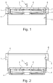
- reference numeral 1 denotes a socket according to the invention, said socket 1 being cup shaped.
- Socket 1 has a guided cover plate 2 to close the socket in a nonoperating state, i.e., with no plug being inserted into the socket. This state is shown in FIG.1 . This is the first position of the cover plate 2.
- Cover plate 2 is movable in axial direction depicted by arrow 3. Cover plate 2 is guided in the socket by its peripheral surface area 4, which slidably interacts with the cylindrical inner surface 5 of the socket, being likewise cylindrical.
- the peripheral surface area 4 of the cover plate follows a spherical profile with its diameter tapering towards the bottom part of the socket 1. In this embodiment the peripheral surface area 4 forms a spherical profile of a ball race shape.
- the cut-spherical peripheral surface area 4 of the cover plate 2 and the cylindrical inner surface 5 of the socket 1 thereby form the first guide means, when interacting with each other.
- a protrusion 6 at the socket's outer opening extends inwardly of the socket's cylindrical insertion well and thus is orientated inwardly to be engaged by the cover plate's outer rim 7.
- the cover plate 2 When engaging said inwardly orientated protrusion 7 at the socket's outer opening in its first position, the cover plate 2 provides a smooth outer appearance of the socket and the cover plate's outer surface 8. The outer surface 8 of the cover plate in its first position is flush with the outer or front-facing edge of the sockets outer opening.
- the cover plate 2 has been moved axially to a second position at the bottom of the socket, i.e., a bottom bearing surface 9 of the socket, as depicted only in FIG. 3 to 6 , 8 and 9 .
- plug and electrical contact pins are not shown in the figures.
- FIG. 3 a view of a detail of the first guide means is displayed.
- the spherical peripheral surface area 4 of the cover plate 2 and the cylindrical inner surface 5 of the socket 1 are shown in the first and the second position of the cover plate 2.
- the cover plate 2 again is displayed in two of its possible positions, i.e., an upper position where the cover plate 2 is tilted according to eccentric pressure 3.1 to the outer surface 8 and in a lower position, where the cover plate 2 has reached its second position. Due to said first guide means the cover plate is not blocked in the upper position and can still be moved down to the second position by pressing it in direction of arrow 3.1.
- FIG. 5 is a view of a socket 2 wherein a cover plate 2 in its first position in the nonoperating state is spring loaded by a helical compression spring 10 acting between said cup shaped socket 1 and said cover plate 2, e.g., between a bottom bearing surface 9 of the socket 5 and the cover plate 2.
- the helical spring 10 is disposed coaxially around a guide pin 11, while in FIG. 6 the helical spring 10 is disposed coaxially to the socket centerline.
- Guide pin 11 outwardly and coaxially protrudes from said cup shaped socket, here respectively from the bottom bearing surface 9 of the socket 1, and may be a PE pin that engages with a corresponding PE contact of the plug (not shown in the figure).
- Both embodiments shown in FIG. 5 and 6 display a second guiding means to guide said cover plate 2 while axially moving down into the socket.
- Said second guiding means act independent from the first guiding means.
- Said second guiding means are provided by sliding interaction between a guide bushing 12 having a guide length L and the guide pin 11 received in said guide bushing.
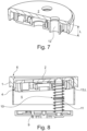
- FIG. 7 is a detailed three-dimensional view of the guide bushing 12 fixed in cover plate 2, having a guide length L for the guide pin.
- said guide length L of the guide bushing is larger than the outer diameter of the guide pin.
- the second guide means complement the first guide means and allow sliding movement of the cover plate even with pressure applied off-centre on the cover plate.
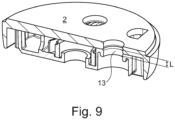
- Both guide bushes 12 and 13 are interchangeable and discrete components of the cover plate 2.
Landscapes
- Connector Housings Or Holding Contact Members (AREA)
- Details Of Connecting Devices For Male And Female Coupling (AREA)
Claims (11)
- Prise de courant (1) pour une jonction débrochable, ladite prise de courant étant en profil de coupe et ayant une plaque couvercle (2) guidée mobile dans une direction axiale pour fermer la prise de courant dans un état de non-fonctionnement sans insertion de fiche dans la prise de courant, ladite plaque couvercle (2) étant guidée dans la prise de courant, en prenant une première position à ressort dans son état de non-fonctionnement, ladite première position étant définie par une saillie orientée vers l'intérieur (6) au niveau de l'ouverture externe de la prise de courant venant en prise avec la plaque couvercle, ladite plaque couvercle (2) étant mobile axialement et/ou en rotation vers une deuxième position au niveau d'une surface de support de dessous (9) de la prise de courant lors de l'insertion et de la poussée d'une fiche jusque dans la prise de courant jusqu'à ce que des broches de contact de la fiche viennent complètement en prise avec des contacts électriques dans la prise de courant, caractérisée en ce qu'un premier moyen de guidage (4, 5) est prévu pour guider ladite plaque couvercle tout en se déplaçant axialement et/ou en rotation jusque dans la prise de courant, le premier moyen de guidage comprenant le fait que la zone de surface périphérique (4) de ladite plaque couvercle interagisse de façon coulissante avec la surface interne cylindrique (5) de la prise de courant, ladite zone de surface périphérique de la plaque couvercle suivant un profil sphérique dont le diamètre se rétrécit vers le fond de la prise de courant.
- Prise de courant selon la revendication 1, dans laquelle ladite zone de surface périphérique de ladite plaque couvercle (2) forme un profil sphérique d'un profil de bague de roulement.
- Prise de courant selon la revendication 1 ou la revendication 2, dans laquelle ladite plaque couvercle (2) dans sa première position dans l'état de non-fonctionnement est à ressort de compression hélicoïdal (10) et/ou à ressort de torsion agissant entre ladite prise de courant en forme de coupe (1) et ladite plaque couvercle (2).
- Prise de courant selon l'une des revendications précédentes 1 à 3, dans laquelle, dans sa première position, une surface externe de la plaque couvercle (2) affleure un bord externe ou tourné vers l'avant de l'ouverture externe de la plaque couvercle lorsque ladite plaque couvercle (2) vient en prise avec ladite saillie orientée vers l'intérieur (6) au niveau de l'ouverture externe de la prise de courant.
- Prise de courant selon l'une des revendications précédentes 1 à 4, dans laquelle au moins un deuxième moyen de guidage (11, 12, 13) est prévu pour guider ladite plaque couvercle tout en se déplaçant axialement et/ou en rotation jusque dans la prise de courant, ledit deuxième moyen de guidage agissant indépendamment par rapport au premier moyen de guidage, ledit deuxième moyen de guidage comprenant une interaction de coulissement entre une bague de guidage (12, 13) ayant une longueur de guidage L et une broche de guidage (11) reçue dans ladite bague de guidage, ladite broche de guidage (11) faisant saillie vers l'extérieur à partir de ladite prise de courant en forme de coupe (1), parallèlement à un axe central de la prise de courant en forme de coupe.
- Prise de courant selon la revendication 5, dans laquelle ladite plaque couvercle, lors de la mise en prise de ladite saillie orientée vers l'intérieur (6) au niveau de l'ouverture externe de la prise de courant dans sa première position de repos, est à ressort hélicoïdal (10) disposé de façon coaxiale autour de ladite broche de guidage (11) et agissant entre la prise de courant en forme de coupe (1) et la plaque couvercle (2).
- Prise de courant selon la revendication 5 ou la revendication 6, dans laquelle ladite longueur de guidage L de ladite bague de guidage (12) est plus grande que le diamètre externe de ladite broche de guidage.
- Prise de courant selon la revendication 5 ou la revendication 6, dans laquelle ladite longueur de guidage L de ladite bague de guidage (13) est plus petite que le diamètre externe de ladite broche de guidage.
- Prise de courant selon la revendication 7 ou la revendication 8, dans laquelle ladite bague de guidage (12, 13) est un composant interchangeable et discret de ladite plaque couvercle.
- Prise de courant selon l'une des revendications précédentes 1 à 9, dans laquelle une pluralité de trous de forage dans ladite plaque couvercle et une pluralité correspondante de contacts électriques de ladite prise de courant en forme de coupe sont prévus, lesdits trous de forage et contacts électriques correspondant à une pluralité de broches de contact d'une fiche.
- Sortie à prises multiples contenant au moins une prise selon l'une des revendications précédentes 1 à 10.
Priority Applications (3)
| Application Number | Priority Date | Filing Date | Title |
|---|---|---|---|
| EP21189931.5A EP4131668B1 (fr) | 2021-08-05 | 2021-08-05 | Prise de courant avec couvercle amovible |
| PL21189931.5T PL4131668T3 (pl) | 2021-08-05 | 2021-08-05 | Gniazdo z ruchomą pokrywą |
| DK21189931.5T DK4131668T3 (da) | 2021-08-05 | 2021-08-05 | Stikkontakt med bevægeligt dæksel |
Applications Claiming Priority (1)
| Application Number | Priority Date | Filing Date | Title |
|---|---|---|---|
| EP21189931.5A EP4131668B1 (fr) | 2021-08-05 | 2021-08-05 | Prise de courant avec couvercle amovible |
Publications (2)
| Publication Number | Publication Date |
|---|---|
| EP4131668A1 EP4131668A1 (fr) | 2023-02-08 |
| EP4131668B1 true EP4131668B1 (fr) | 2024-03-27 |
Family
ID=77226733
Family Applications (1)
| Application Number | Title | Priority Date | Filing Date |
|---|---|---|---|
| EP21189931.5A Active EP4131668B1 (fr) | 2021-08-05 | 2021-08-05 | Prise de courant avec couvercle amovible |
Country Status (3)
| Country | Link |
|---|---|
| EP (1) | EP4131668B1 (fr) |
| DK (1) | DK4131668T3 (fr) |
| PL (1) | PL4131668T3 (fr) |
Family Cites Families (4)
| Publication number | Priority date | Publication date | Assignee | Title |
|---|---|---|---|---|
| IT1000801B (it) | 1973-12-05 | 1976-04-10 | Bassani Spa | Dispositivo di sicurezza per prese di corrente elettrica |
| DE2701188A1 (de) * | 1977-01-13 | 1978-07-20 | Artur Sauer | Elektrische steckdose |
| US5944542A (en) * | 1997-06-27 | 1999-08-31 | Han Y. Lee | Plug safety adapter for anti-electric shock |
| US8075325B1 (en) * | 2010-11-02 | 2011-12-13 | Standard Cable USA, Inc. | Self-cleaning electrical connection assembly |
-
2021
- 2021-08-05 PL PL21189931.5T patent/PL4131668T3/pl unknown
- 2021-08-05 DK DK21189931.5T patent/DK4131668T3/da active
- 2021-08-05 EP EP21189931.5A patent/EP4131668B1/fr active Active
Also Published As
| Publication number | Publication date |
|---|---|
| PL4131668T3 (pl) | 2024-08-05 |
| DK4131668T3 (da) | 2024-06-24 |
| EP4131668A1 (fr) | 2023-02-08 |
Similar Documents
| Publication | Publication Date | Title |
|---|---|---|
| JP6840640B2 (ja) | コネクタ装置 | |
| JP6875599B2 (ja) | 係止要素を備えた電気コネクタ部品 | |
| KR102041924B1 (ko) | 커넥터 | |
| US5893782A (en) | Single-pole contact system | |
| KR102252303B1 (ko) | 누름버튼 스위치 | |
| WO2016186733A1 (fr) | Verrou pour connecteur électrique | |
| US20090305537A1 (en) | Electrical Safety Socket Device | |
| JP6793190B2 (ja) | 小型連動型電気ソケット | |
| CN105917528B (zh) | 电气模块 | |
| JP2019517724A (ja) | コンパクトプラグアダプタ | |
| DE102004034321B3 (de) | Elektrischer Steckverbinder | |
| EP3767133A1 (fr) | Actionneur | |
| EP4131668B1 (fr) | Prise de courant avec couvercle amovible | |
| HK1207747A1 (en) | Plug | |
| KR102255613B1 (ko) | 누름버튼 스위치 | |
| JP6513542B2 (ja) | コネクタ及びコネクタ組立体 | |
| CN114696160A (zh) | 连接器装置 | |
| JP2022553557A (ja) | 導電体を接続するための端子装置 | |
| EP0630076A1 (fr) | Construction de connecteur ayant des leviers | |
| KR102252304B1 (ko) | 누름버튼 스위치 | |
| CN100359353C (zh) | 连接装置 | |
| CN1792010B (zh) | 插头适配器 | |
| CN107689505B (zh) | 插座用保护门组件和插座 | |
| WO2011107416A1 (fr) | Connecteur électrique | |
| US6450827B1 (en) | Socket having mating indicator |
Legal Events
| Date | Code | Title | Description |
|---|---|---|---|
| PUAI | Public reference made under article 153(3) epc to a published international application that has entered the european phase |
Free format text: ORIGINAL CODE: 0009012 |
|
| STAA | Information on the status of an ep patent application or granted ep patent |
Free format text: STATUS: THE APPLICATION HAS BEEN PUBLISHED |
|
| AK | Designated contracting states |
Kind code of ref document: A1 Designated state(s): AL AT BE BG CH CY CZ DE DK EE ES FI FR GB GR HR HU IE IS IT LI LT LU LV MC MK MT NL NO PL PT RO RS SE SI SK SM TR |
|
| P01 | Opt-out of the competence of the unified patent court (upc) registered |
Effective date: 20230606 |
|
| STAA | Information on the status of an ep patent application or granted ep patent |
Free format text: STATUS: REQUEST FOR EXAMINATION WAS MADE |
|
| 17P | Request for examination filed |
Effective date: 20230802 |
|
| RBV | Designated contracting states (corrected) |
Designated state(s): AL AT BE BG CH CY CZ DE DK EE ES FI FR GB GR HR HU IE IS IT LI LT LU LV MC MK MT NL NO PL PT RO RS SE SI SK SM TR |
|
| GRAP | Despatch of communication of intention to grant a patent |
Free format text: ORIGINAL CODE: EPIDOSNIGR1 |
|
| STAA | Information on the status of an ep patent application or granted ep patent |
Free format text: STATUS: GRANT OF PATENT IS INTENDED |
|
| INTG | Intention to grant announced |
Effective date: 20231201 |
|
| GRAS | Grant fee paid |
Free format text: ORIGINAL CODE: EPIDOSNIGR3 |
|
| GRAA | (expected) grant |
Free format text: ORIGINAL CODE: 0009210 |
|
| STAA | Information on the status of an ep patent application or granted ep patent |
Free format text: STATUS: THE PATENT HAS BEEN GRANTED |
|
| AK | Designated contracting states |
Kind code of ref document: B1 Designated state(s): AL AT BE BG CH CY CZ DE DK EE ES FI FR GB GR HR HU IE IS IT LI LT LU LV MC MK MT NL NO PL PT RO RS SE SI SK SM TR |
|
| REG | Reference to a national code |
Ref country code: GB Ref legal event code: FG4D |
|
| REG | Reference to a national code |
Ref country code: CH Ref legal event code: EP |
|
| REG | Reference to a national code |
Ref country code: DE Ref legal event code: R096 Ref document number: 602021010865 Country of ref document: DE |
|
| REG | Reference to a national code |
Ref country code: IE Ref legal event code: FG4D |
|
| REG | Reference to a national code |
Ref country code: DK Ref legal event code: T3 Effective date: 20240620 |
|
| PG25 | Lapsed in a contracting state [announced via postgrant information from national office to epo] |
Ref country code: LT Free format text: LAPSE BECAUSE OF FAILURE TO SUBMIT A TRANSLATION OF THE DESCRIPTION OR TO PAY THE FEE WITHIN THE PRESCRIBED TIME-LIMIT Effective date: 20240327 |
|
| REG | Reference to a national code |
Ref country code: LT Ref legal event code: MG9D |
|
| PG25 | Lapsed in a contracting state [announced via postgrant information from national office to epo] |
Ref country code: GR Free format text: LAPSE BECAUSE OF FAILURE TO SUBMIT A TRANSLATION OF THE DESCRIPTION OR TO PAY THE FEE WITHIN THE PRESCRIBED TIME-LIMIT Effective date: 20240628 |
|
| PG25 | Lapsed in a contracting state [announced via postgrant information from national office to epo] |
Ref country code: RS Free format text: LAPSE BECAUSE OF FAILURE TO SUBMIT A TRANSLATION OF THE DESCRIPTION OR TO PAY THE FEE WITHIN THE PRESCRIBED TIME-LIMIT Effective date: 20240627 Ref country code: HR Free format text: LAPSE BECAUSE OF FAILURE TO SUBMIT A TRANSLATION OF THE DESCRIPTION OR TO PAY THE FEE WITHIN THE PRESCRIBED TIME-LIMIT Effective date: 20240327 |
|
| PG25 | Lapsed in a contracting state [announced via postgrant information from national office to epo] |
Ref country code: RS Free format text: LAPSE BECAUSE OF FAILURE TO SUBMIT A TRANSLATION OF THE DESCRIPTION OR TO PAY THE FEE WITHIN THE PRESCRIBED TIME-LIMIT Effective date: 20240627 Ref country code: NO Free format text: LAPSE BECAUSE OF FAILURE TO SUBMIT A TRANSLATION OF THE DESCRIPTION OR TO PAY THE FEE WITHIN THE PRESCRIBED TIME-LIMIT Effective date: 20240627 Ref country code: LT Free format text: LAPSE BECAUSE OF FAILURE TO SUBMIT A TRANSLATION OF THE DESCRIPTION OR TO PAY THE FEE WITHIN THE PRESCRIBED TIME-LIMIT Effective date: 20240327 Ref country code: HR Free format text: LAPSE BECAUSE OF FAILURE TO SUBMIT A TRANSLATION OF THE DESCRIPTION OR TO PAY THE FEE WITHIN THE PRESCRIBED TIME-LIMIT Effective date: 20240327 Ref country code: GR Free format text: LAPSE BECAUSE OF FAILURE TO SUBMIT A TRANSLATION OF THE DESCRIPTION OR TO PAY THE FEE WITHIN THE PRESCRIBED TIME-LIMIT Effective date: 20240628 Ref country code: FI Free format text: LAPSE BECAUSE OF FAILURE TO SUBMIT A TRANSLATION OF THE DESCRIPTION OR TO PAY THE FEE WITHIN THE PRESCRIBED TIME-LIMIT Effective date: 20240327 Ref country code: BG Free format text: LAPSE BECAUSE OF FAILURE TO SUBMIT A TRANSLATION OF THE DESCRIPTION OR TO PAY THE FEE WITHIN THE PRESCRIBED TIME-LIMIT Effective date: 20240327 |
|
| REG | Reference to a national code |
Ref country code: NL Ref legal event code: MP Effective date: 20240327 |
|
| PG25 | Lapsed in a contracting state [announced via postgrant information from national office to epo] |
Ref country code: SE Free format text: LAPSE BECAUSE OF FAILURE TO SUBMIT A TRANSLATION OF THE DESCRIPTION OR TO PAY THE FEE WITHIN THE PRESCRIBED TIME-LIMIT Effective date: 20240327 Ref country code: LV Free format text: LAPSE BECAUSE OF FAILURE TO SUBMIT A TRANSLATION OF THE DESCRIPTION OR TO PAY THE FEE WITHIN THE PRESCRIBED TIME-LIMIT Effective date: 20240327 |
|
| PG25 | Lapsed in a contracting state [announced via postgrant information from national office to epo] |
Ref country code: NL Free format text: LAPSE BECAUSE OF FAILURE TO SUBMIT A TRANSLATION OF THE DESCRIPTION OR TO PAY THE FEE WITHIN THE PRESCRIBED TIME-LIMIT Effective date: 20240327 |
|
| REG | Reference to a national code |
Ref country code: AT Ref legal event code: MK05 Ref document number: 1670828 Country of ref document: AT Kind code of ref document: T Effective date: 20240327 |
|
| PG25 | Lapsed in a contracting state [announced via postgrant information from national office to epo] |
Ref country code: NL Free format text: LAPSE BECAUSE OF FAILURE TO SUBMIT A TRANSLATION OF THE DESCRIPTION OR TO PAY THE FEE WITHIN THE PRESCRIBED TIME-LIMIT Effective date: 20240327 |
|
| PG25 | Lapsed in a contracting state [announced via postgrant information from national office to epo] |
Ref country code: IS Free format text: LAPSE BECAUSE OF FAILURE TO SUBMIT A TRANSLATION OF THE DESCRIPTION OR TO PAY THE FEE WITHIN THE PRESCRIBED TIME-LIMIT Effective date: 20240727 |
|
| PG25 | Lapsed in a contracting state [announced via postgrant information from national office to epo] |
Ref country code: SM Free format text: LAPSE BECAUSE OF FAILURE TO SUBMIT A TRANSLATION OF THE DESCRIPTION OR TO PAY THE FEE WITHIN THE PRESCRIBED TIME-LIMIT Effective date: 20240327 Ref country code: PT Free format text: LAPSE BECAUSE OF FAILURE TO SUBMIT A TRANSLATION OF THE DESCRIPTION OR TO PAY THE FEE WITHIN THE PRESCRIBED TIME-LIMIT Effective date: 20240729 |
|
| PG25 | Lapsed in a contracting state [announced via postgrant information from national office to epo] |
Ref country code: ES Free format text: LAPSE BECAUSE OF FAILURE TO SUBMIT A TRANSLATION OF THE DESCRIPTION OR TO PAY THE FEE WITHIN THE PRESCRIBED TIME-LIMIT Effective date: 20240327 |
|
| PG25 | Lapsed in a contracting state [announced via postgrant information from national office to epo] |
Ref country code: CZ Free format text: LAPSE BECAUSE OF FAILURE TO SUBMIT A TRANSLATION OF THE DESCRIPTION OR TO PAY THE FEE WITHIN THE PRESCRIBED TIME-LIMIT Effective date: 20240327 Ref country code: EE Free format text: LAPSE BECAUSE OF FAILURE TO SUBMIT A TRANSLATION OF THE DESCRIPTION OR TO PAY THE FEE WITHIN THE PRESCRIBED TIME-LIMIT Effective date: 20240327 |
|
| PG25 | Lapsed in a contracting state [announced via postgrant information from national office to epo] |
Ref country code: AT Free format text: LAPSE BECAUSE OF FAILURE TO SUBMIT A TRANSLATION OF THE DESCRIPTION OR TO PAY THE FEE WITHIN THE PRESCRIBED TIME-LIMIT Effective date: 20240327 |
|
| PG25 | Lapsed in a contracting state [announced via postgrant information from national office to epo] |
Ref country code: SK Free format text: LAPSE BECAUSE OF FAILURE TO SUBMIT A TRANSLATION OF THE DESCRIPTION OR TO PAY THE FEE WITHIN THE PRESCRIBED TIME-LIMIT Effective date: 20240327 |
|
| PG25 | Lapsed in a contracting state [announced via postgrant information from national office to epo] |
Ref country code: SM Free format text: LAPSE BECAUSE OF FAILURE TO SUBMIT A TRANSLATION OF THE DESCRIPTION OR TO PAY THE FEE WITHIN THE PRESCRIBED TIME-LIMIT Effective date: 20240327 Ref country code: SK Free format text: LAPSE BECAUSE OF FAILURE TO SUBMIT A TRANSLATION OF THE DESCRIPTION OR TO PAY THE FEE WITHIN THE PRESCRIBED TIME-LIMIT Effective date: 20240327 Ref country code: RO Free format text: LAPSE BECAUSE OF FAILURE TO SUBMIT A TRANSLATION OF THE DESCRIPTION OR TO PAY THE FEE WITHIN THE PRESCRIBED TIME-LIMIT Effective date: 20240327 Ref country code: PT Free format text: LAPSE BECAUSE OF FAILURE TO SUBMIT A TRANSLATION OF THE DESCRIPTION OR TO PAY THE FEE WITHIN THE PRESCRIBED TIME-LIMIT Effective date: 20240729 Ref country code: IS Free format text: LAPSE BECAUSE OF FAILURE TO SUBMIT A TRANSLATION OF THE DESCRIPTION OR TO PAY THE FEE WITHIN THE PRESCRIBED TIME-LIMIT Effective date: 20240727 Ref country code: ES Free format text: LAPSE BECAUSE OF FAILURE TO SUBMIT A TRANSLATION OF THE DESCRIPTION OR TO PAY THE FEE WITHIN THE PRESCRIBED TIME-LIMIT Effective date: 20240327 Ref country code: EE Free format text: LAPSE BECAUSE OF FAILURE TO SUBMIT A TRANSLATION OF THE DESCRIPTION OR TO PAY THE FEE WITHIN THE PRESCRIBED TIME-LIMIT Effective date: 20240327 Ref country code: CZ Free format text: LAPSE BECAUSE OF FAILURE TO SUBMIT A TRANSLATION OF THE DESCRIPTION OR TO PAY THE FEE WITHIN THE PRESCRIBED TIME-LIMIT Effective date: 20240327 Ref country code: AT Free format text: LAPSE BECAUSE OF FAILURE TO SUBMIT A TRANSLATION OF THE DESCRIPTION OR TO PAY THE FEE WITHIN THE PRESCRIBED TIME-LIMIT Effective date: 20240327 |
|
| PG25 | Lapsed in a contracting state [announced via postgrant information from national office to epo] |
Ref country code: IT Free format text: LAPSE BECAUSE OF FAILURE TO SUBMIT A TRANSLATION OF THE DESCRIPTION OR TO PAY THE FEE WITHIN THE PRESCRIBED TIME-LIMIT Effective date: 20240327 |
|
| PG25 | Lapsed in a contracting state [announced via postgrant information from national office to epo] |
Ref country code: IT Free format text: LAPSE BECAUSE OF FAILURE TO SUBMIT A TRANSLATION OF THE DESCRIPTION OR TO PAY THE FEE WITHIN THE PRESCRIBED TIME-LIMIT Effective date: 20240327 |
|
| REG | Reference to a national code |
Ref country code: DE Ref legal event code: R097 Ref document number: 602021010865 Country of ref document: DE |
|
| PLBE | No opposition filed within time limit |
Free format text: ORIGINAL CODE: 0009261 |
|
| STAA | Information on the status of an ep patent application or granted ep patent |
Free format text: STATUS: NO OPPOSITION FILED WITHIN TIME LIMIT |
|
| REG | Reference to a national code |
Ref country code: DE Ref legal event code: R119 Ref document number: 602021010865 Country of ref document: DE |
|
| 26N | No opposition filed |
Effective date: 20250103 |
|
| REG | Reference to a national code |
Ref country code: CH Ref legal event code: PL |
|
| PG25 | Lapsed in a contracting state [announced via postgrant information from national office to epo] |
Ref country code: LU Free format text: LAPSE BECAUSE OF NON-PAYMENT OF DUE FEES Effective date: 20240805 |
|
| PG25 | Lapsed in a contracting state [announced via postgrant information from national office to epo] |
Ref country code: CH Free format text: LAPSE BECAUSE OF NON-PAYMENT OF DUE FEES Effective date: 20240831 Ref country code: SI Free format text: LAPSE BECAUSE OF FAILURE TO SUBMIT A TRANSLATION OF THE DESCRIPTION OR TO PAY THE FEE WITHIN THE PRESCRIBED TIME-LIMIT Effective date: 20240327 Ref country code: MC Free format text: LAPSE BECAUSE OF FAILURE TO SUBMIT A TRANSLATION OF THE DESCRIPTION OR TO PAY THE FEE WITHIN THE PRESCRIBED TIME-LIMIT Effective date: 20240327 |
|
| PG25 | Lapsed in a contracting state [announced via postgrant information from national office to epo] |
Ref country code: DE Free format text: LAPSE BECAUSE OF NON-PAYMENT OF DUE FEES Effective date: 20250301 |
|
| PG25 | Lapsed in a contracting state [announced via postgrant information from national office to epo] |
Ref country code: IE Free format text: LAPSE BECAUSE OF NON-PAYMENT OF DUE FEES Effective date: 20240805 |
|
| PGFP | Annual fee paid to national office [announced via postgrant information from national office to epo] |
Ref country code: DK Payment date: 20250825 Year of fee payment: 5 |
|
| PGFP | Annual fee paid to national office [announced via postgrant information from national office to epo] |
Ref country code: PL Payment date: 20250722 Year of fee payment: 5 |
|
| PGFP | Annual fee paid to national office [announced via postgrant information from national office to epo] |
Ref country code: BE Payment date: 20250827 Year of fee payment: 5 |
|
| PGFP | Annual fee paid to national office [announced via postgrant information from national office to epo] |
Ref country code: FR Payment date: 20250825 Year of fee payment: 5 |
|
| PG25 | Lapsed in a contracting state [announced via postgrant information from national office to epo] |
Ref country code: CY Free format text: LAPSE BECAUSE OF FAILURE TO SUBMIT A TRANSLATION OF THE DESCRIPTION OR TO PAY THE FEE WITHIN THE PRESCRIBED TIME-LIMIT; INVALID AB INITIO Effective date: 20210805 |
|
| PG25 | Lapsed in a contracting state [announced via postgrant information from national office to epo] |
Ref country code: HU Free format text: LAPSE BECAUSE OF FAILURE TO SUBMIT A TRANSLATION OF THE DESCRIPTION OR TO PAY THE FEE WITHIN THE PRESCRIBED TIME-LIMIT; INVALID AB INITIO Effective date: 20210805 |