EP4131685A1 - Unité de canalisation pouvant être raccordée et canalisation - Google Patents
Unité de canalisation pouvant être raccordée et canalisation Download PDFInfo
- Publication number
- EP4131685A1 EP4131685A1 EP21189702.0A EP21189702A EP4131685A1 EP 4131685 A1 EP4131685 A1 EP 4131685A1 EP 21189702 A EP21189702 A EP 21189702A EP 4131685 A1 EP4131685 A1 EP 4131685A1
- Authority
- EP
- European Patent Office
- Prior art keywords
- cable duct
- duct unit
- coupling
- another
- end pieces
- Prior art date
- Legal status (The legal status is an assumption and is not a legal conclusion. Google has not performed a legal analysis and makes no representation as to the accuracy of the status listed.)
- Withdrawn
Links
Images



Classifications
-
- H—ELECTRICITY
- H02—GENERATION; CONVERSION OR DISTRIBUTION OF ELECTRIC POWER
- H02G—INSTALLATION OF ELECTRIC CABLES OR LINES, OR OF COMBINED OPTICAL AND ELECTRIC CABLES OR LINES
- H02G3/00—Installations of electric cables or lines or protective tubing therefor in or on buildings, equivalent structures or vehicles
- H02G3/02—Details
- H02G3/06—Joints for connecting lengths of protective tubing or channels, to each other or to casings, e.g. to distribution boxes; Ensuring electrical continuity in the joint
- H02G3/0608—Joints for connecting non cylindrical conduits, e.g. channels
-
- F—MECHANICAL ENGINEERING; LIGHTING; HEATING; WEAPONS; BLASTING
- F16—ENGINEERING ELEMENTS AND UNITS; GENERAL MEASURES FOR PRODUCING AND MAINTAINING EFFECTIVE FUNCTIONING OF MACHINES OR INSTALLATIONS; THERMAL INSULATION IN GENERAL
- F16L—PIPES; JOINTS OR FITTINGS FOR PIPES; SUPPORTS FOR PIPES, CABLES OR PROTECTIVE TUBING; MEANS FOR THERMAL INSULATION IN GENERAL
- F16L3/00—Supports for pipes, cables or protective tubing, e.g. hangers, holders, clamps, cleats, clips, brackets
- F16L3/26—Supports for pipes, cables or protective tubing, e.g. hangers, holders, clamps, cleats, clips, brackets specially adapted for supporting the pipes all along their length, e.g. pipe channels or ducts
-
- H—ELECTRICITY
- H02—GENERATION; CONVERSION OR DISTRIBUTION OF ELECTRIC POWER
- H02G—INSTALLATION OF ELECTRIC CABLES OR LINES, OR OF COMBINED OPTICAL AND ELECTRIC CABLES OR LINES
- H02G3/00—Installations of electric cables or lines or protective tubing therefor in or on buildings, equivalent structures or vehicles
- H02G3/02—Details
- H02G3/04—Protective tubing or conduits, e.g. cable ladders or cable troughs
- H02G3/0437—Channels
Definitions
- the invention relates to a connectable cable duct unit and a cable duct with a plurality of cable duct units connected to one another.
- cables In commercial, industrial and administration buildings as well as in tunnels, cables, especially cables for high and low current networks, lines and pipes, are often laid in metal cable trays, such as cable ducts or cable racks, due to a lack of inherent stability, and are thus routed, for example, from a control panel or a control center led to consumers.
- Cable tracks of this type which are assembled from individual cable track sections, are known, for example, from the product catalog of LANZ OENSINGEN AG, July 2017. Devices that are also described in this product catalog can be used to connect the cable track sections.
- Each cable duct unit comprises at one end a first connection portion connectable to a second connection portion of a second cable duct unit and at the other end a second connection portion connectable to a first connection portion of a third cable duct unit.
- the first connection section is formed at a first end of a cable duct unit by a cranked portion that increases the cross-sectional area of the cable duct unit and is suitable for receiving an uncrimped second connection section that is provided at a second end of a further cable duct unit.
- a first and a second connecting section can thus be slid into one another and locked in place by latching elements and locking elements.
- each cable duct unit The two connecting sections of each cable duct unit are designed to be complementary to one another but different, which is why when installing a cable duct, care must be taken to ensure that the cable duct units are aligned with one another with the appropriate connecting sections. Since cable ducts are usually installed on a building ceiling of a building that has not yet been completed, the cable ducts are usually installed under difficult conditions. On the one hand, the fitters typically stand on ladders or platforms, which is why they are restricted in their freedom of movement and primarily have to pay attention to their safety. On the other hand, the room lighting is usually poor, so the installer often cannot distinguish the connection sections of a supported trunking unit from each other. The installation of a cable duct with such cable duct units is therefore often associated with difficulties.
- the assembly of the additional connecting means to create a good electrical contact is also associated with additional effort.
- the connecting sections of the cable duct units DE202009004970U1 are connected to one another with an assembly movement in a direction transverse to the longitudinal extension of the cable duct units. It is therefore necessary for the installer to keep the connecting sections one above the other and in one precise mutual alignment in order to subsequently be able to shift them into one another. Furthermore, lifting the cable duct unit to be connected requires strength and skill. Since the cable duct unit to be connected can hardly be lifted in a horizontal position, tilting and blocking can occur when connecting. The fitter must therefore take a position exactly at the connection point in order to be able to monitor the connection process in good light conditions and to be able to carry it out with the necessary skill. For this purpose, a stage may have to be moved to the relevant position and bright lighting provided.
- the present invention is therefore based on the object of creating an improved connectable cable duct unit and an improved cable duct with such cable duct units.
- the cable duct units should be able to be put together in a simple manner even under difficult spatial and lighting conditions, so that the cable run to be installed can be set up quickly and without endangering the personnel.
- the operation of connecting the trunking units shall be accomplished with a simple linear movement of a trunking unit. Lifting a cable duct unit should be avoided if possible.
- the cable duct units should have a simple structure and be able to be manufactured with little effort.
- connection of the cable duct units should be possible without the use of screws.
- the connectable cable duct unit comprises a base element, which runs parallel to a central axis of the cable duct unit and is connected to side pieces on both sides, and end pieces provided at both ends of the cable duct unit, which can each be connected to an end piece of an adjacent cable duct unit.
- the two end pieces of the cable duct unit are designed at least approximately identically and rotated through 180° in relation to one another and each have a first coupling plate and a second coupling plate, which are separated from one another laterally along the central axis by a central gap and are designed in such a way that they or are slidable under a corresponding second coupling plate or first coupling plate of the adjacent cable duct unit and are provided with first coupling elements which are intended to engage in corresponding first coupling elements of the coupling plates of the adjacent cable duct unit.
- the end pieces are thus asymmetrical with respect to the central axis and comprise a first part on one side of the central axis and a second part on the other side of the central axis.
- the end pieces provided for connecting the cable duct units are preferably identical, but can differ in design as long as this does not impair the ability to connect.
- end pieces of the cable duct unit are identical but rotated 180° relative to one another, end pieces of adjacent cable duct units can always be connected to one another in a simple manner, regardless of the orientation of the cable duct units.
- the mutually facing end pieces are not only complementary to one another, but also identical, so that a first coupling plate and a second coupling plate can overlap on both sides of the central axis.
- Two cable duct units are connected in a simple manner by sliding the end pieces, which are aligned coaxially with one another, into one another or by pushing the end pieces inclined towards one another along the central axis and coupling them, after which the second cable duct unit is rotated against the first cable duct unit to create the connection.
- the coupling of the cable duct units takes place by the floor element of the first cable duct unit in the middle gap of the floor element of the second cable duct unit and the floor element of the second cable duct unit in the Central gap of the floor element of the first cable duct unit is pushed.
- a connection between the cable duct units thus results in a simple manner, the rotation of the second cable duct unit can be completed.
- the channel units can thus be displaced relative to one another along their longitudinal axis and coupled to one another and preferably latched. It is therefore not necessary to lift any of the cable duct units, which makes the installation process much easier.
- the cable duct units to be connected are placed on brackets, aligned coaxially with one another and then pushed into one another. This sliding process can be carried out comfortably and without effort. Since only the cable duct units have to be aligned coaxially with one another, it is not necessary to determine the exact mutual position of coupling elements one above the other, which gives the fitter greater freedom, who can also carry out the connection process at a slightly greater distance from the connection point. Since the two cable duct units and coupling elements that are not on top of one another must be aligned with one another, the connection process can be carried out without any problems, even in poor lighting conditions where smaller coupling elements are difficult to see.
- connection by axial displacement and the connection by axial displacement rotation can be easily implemented by the fitter.
- connection of the trunking units is made by axial displacement and with reference to 6 the connection of the cable duct units is described by axial displacement and rotation.
- Cable duct units according to the invention can therefore be connected to one another without any problems even under difficult conditions, for example standing on a ladder in poor light conditions.
- the first coupling plate and the second coupling plate are preferably shifted in height relative to one another in relation to the base element.
- at least one of the coupling plates is at least partially inclined or curved. Provision is particularly preferably made for the first coupling plate, which can be slid under the second coupling plate of the adjacent cable duct unit when two cable duct units are connected, to be bent downwards entirely or at least at the front.
- the curved part of the first coupling plate lies on the underside of the floor element and does not come into contact with cables that are laid in the cable duct.
- the two end pieces of the cable duct unit each have a first end piece of one side piece and a second end piece of the other side piece, which are designed to be complementary to one another and have second coupling elements that are complementary to one another.
- the Side pieces of the cable duct unit are designed as walls, for example.
- the coupling elements engage in one another.
- connection of the side pieces also allows the coupling plates to be pushed against one another precisely, at least to some extent, with the connection or latching of the coupling elements.
- the coupling plates and/or the end pieces have assembly openings that correspond to one another and are preferably aligned longitudinally and transversely to one another, through which a connecting element, such as a connecting screw, can be guided in order to create a mechanical and electrical connection.
- a connecting element such as a connecting screw
- a round-head screw is guided from the inside of the duct through the assembly openings of the overlapping coupling plates and/or end pieces and fixed by means of a nut.
- the rounded head of the round-head screw which rests against the inside of the side wall or the floor within the channel cross-section, does not form an obstacle for inserted cables.
- the first and/or second coupling elements are preferably locking elements, such as openings and cams or hooks that can be anchored therein.
- a locking connection is preferably created automatically. This locking connection can be released by raising the coupling plates or separating the end pieces from one another.
- at least one of the mutually corresponding coupling elements is provided with a run-up ramp, which allows the coupling elements to be easily pushed into one another until the latching process is complete.
- the run-up ramps rise in the direction of the longitudinal axis in the cable duct units and, when the end pieces are pushed against one another, preferably reach with a wedge edge under or over the adjacent coupling plate.
- the coupling plates preferably form elastic latching tongues which are bent when the cable duct units are pushed against one another until the coupling elements can latch.
- At least one of the coupling plates is preferably separated from the associated side piece, which may be wall-shaped, by a gap. By exposing the coupling plates on both sides, they therefore attain a desired flexibility.
- the first and / or second coupling elements are preferably aligned such that they mutual displacement of interconnected cable duct units along the Central axis or inclined to prevent. At least one first coupling element is preferably provided, which can absorb tensile forces parallel to the central axis. Furthermore, at least one second coupling element is preferably provided, which can absorb a force perpendicular to the central axis and secures the connection of the cable duct units.
- the coupling elements are preferably designed as slot openings and matching bar-shaped cams.
- the corresponding coupling openings are preferably punched out and the e.g. bar-shaped cams are cut free at the side and bent out.
- Coupling elements can be implemented in any way. These are preferably incorporated into the material of the cable duct unit.
- the end pieces on the other hand, can also be provided with separately manufactured coupling elements.
- the side pieces or side walls of the cable duct units preferably have outwardly rolled edge pieces on the side facing away from the floor element, which are designed to complement one another in the area of the first end piece and the second end piece and have different dimensions, so that the edge pieces of first and second end pieces that correspond to one another can be moved.
- the coupling plates and/or the end pieces are preferably manufactured by molding operations and/or stamping operations.
- the cable duct unit can therefore advantageously be manufactured from a suitably tailored sheet metal piece.
- the connectability or pluggability of the cable duct units is advantageously increased.
- the base element and/or the side pieces of the cable duct unit are preferably provided with perforations that allow the cables laid in the cable duct to be ventilated and cooled.
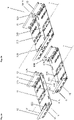
- Fig. 1a shows in a preferred embodiment two separate cable duct units 1A, 1B according to the invention on the left and two identical interconnected cable duct units 1A, 1B on the right.
- the cable duct units 1A, 1B comprise a base element 11, which runs parallel to a central axis x and is connected on both sides to side pieces in the form of side walls 12.
- each cable duct unit 1A, 1B has an end piece 5 which can be connected to any end piece 5 of an adjacent cable duct unit 1B according to the invention.
- a first Cable duct unit 1A can therefore be connected to an arbitrarily oriented second cable unit 1B.
- the two cable duct units 1A, 1B are connected in a simple manner by sliding the end pieces 5, which are correctly aligned with one another, into one another or by pushing the end pieces 5 inclined towards one another along the central axis x and coupling them, after which the second cable duct unit 1B is turned against the first cable duct unit 1A.
- connection of the cable duct units 1A, 1B by sliding them into each other and then, with reference to FIG figure 5 the connection is described by sliding and rotating into each other.
- Figure 2a shows the mutually facing end pieces 5 of the separate cable duct units 1A, 1B of FIG 1 .
- the two end pieces 5 of the cable duct units 1A, 1B are of identical design and rotated by 180° in relation to one another and each comprise a first coupling plate 51A and a second coupling plate 51B. Consequently, the end pieces 5 of each cable duct unit 1A or 1B are also rotated through 180° relative to one another.
- the coupling plates 51A, 51B are laterally separated from one another along the central axis x by a central gap 515 and are shifted in height relative to one another in relation to the base element 11 .
- the height of the coupling plates 51A, 51B is shifted relative to one another in such a way that they can be pushed past one another at a small distance or with practically no play, or if necessary be elastically bent during the shifting process.
- the mutually directed front end pieces 516 of at least one coupling plate 51A, 51B are inclined or bent about an axis of inclination that runs perpendicular to the central axis x, so that the coupling plates 51A, 51B can move against one another without hitting the ends.
- the coupling plates 51A, 51B are displaced upwards and downwards and, after the coupling elements have engaged, preferably contact one another with a pressing force. In this way, the connection of the coupling elements is reliably secured.
- At least one of the coupling plates 51A, 51B is designed to be elastic so that it forms a latching tongue which can be bent back until it latches.
- the two end pieces 5 of the cable duct unit 1A also each have a first end piece 52A on one side piece or a side wall 12 and a second end piece 52B on the other side piece or the other side wall 12 of the cable duct unit 1A.
- the end pieces 52A, 52B are complementary to one another or complementary to corresponding end pieces 52B, 52A of the adjacent cable duct unit 1B and have mutually complementary second coupling elements 520, 521 which after the coupling of adjacent cable duct units 1A; 1B, in which the first and second end pieces 52A, 52B, which correspond to one another on both sides of the central axis x, lie laterally next to one another and engage in one another.
- Figure 2b 12 shows the end pieces 5 of the cable duct units 1A, 1B of FIG 1 , with the coupling plates 51A, 51B being superimposed and coupled to each other. It can be seen that the second coupling plates 51B overlap the first coupling plates 51B. Furthermore, it can be seen that the second end pieces 52B overlap the first end pieces 52B.
- FIG. 3 shows the mutually facing end pieces 5 of the separate cable duct units 1A, 1B of FIG Figure 2a in an enlarged view.
- the coupling plates 51A, 51B or 51B, 51A of the end pieces 5 of the two cable duct sections 1A, 1B have first coupling elements 510, 511 which correspond to one another.
- Longitudinal openings 510 are provided in the first coupling plate 51A, into which bar-shaped locking elements 511 can enter, which are cut out and bent out of the second coupling plate 51B.
- the coupling elements 510, 511 are aligned transversely to the central axis x in order to be able to absorb high tensile forces along the central axis x.
- the end pieces 52A, 52B also have a plurality of coupling elements 520, 521 which can snap into one another.
- Two longitudinal openings 520 aligned perpendicularly to the center axis x are provided in the first end piece 52A, into which bar-shaped latching elements 521 can enter, which are cut out and bent out of the second end piece 52B.
- These coupling elements 520, 521 in turn absorb tensile forces that act parallel to the central axis x.
- the first end piece 52A has a longitudinal opening running parallel to the central axis x, into which a latching element 521 cut out and bent out of the second end piece 52B can engage.
- the second end piece 52B is lateral with respect to the central axis x shifted relative to the associated side piece 12 and possibly slightly inclined at the front.
- FIG. 12 further shows that the two side pieces 12 have outwardly rolled, at least approximately cylindrical edge pieces 121, which are designed to be complementary to one another in the area of the first end piece 52A and the second end piece 52B and have different dimensions.
- the edge pieces 121, 1215 of the mutually corresponding end pieces 52A, 52B of two adjacent cable duct units 1A, 1B can therefore be pushed into one another.
- the edge piece 1215 of the second end piece 52B is expanded so that the unchanged edge piece 121 of the first end piece 52A can be inserted therein.
- the edge piece 1215 of the second end piece 52B is preferably flared so that the coupling is easy to achieve.
- the end pieces 52A, 52B have mutually corresponding mounting openings 528, which are slightly oval and aligned vertically or horizontally to compensate for tolerances.
- Connecting means such as the connecting screw 91 shown, which is connected to a screw nut 92, can be guided through these assembly openings 528.
- the connecting screw 91 has a round head which rests against the inside of the side piece or the side wall 12 and does not form an obstacle for inserted cables. When pulling in the cable, the cable sheath can therefore not be damaged.
- one of the coupling plates 51A, 51B is to be bent and/or has increased flexibility and is to serve as a latching tongue, for example, it is preferably exposed on both sides through a cut, the central gap 515 and a side gap 525, which connects the base element 11 and the side piece or separating the side wall 12 from each other.
- the metal first Therefore, the coupling plate 51A can be bent and also has increased flexibility.
- FIG. 12 shows parts of the mutually facing end pieces 5 of the separate cable duct units 1A, 1B of FIG 3 in a further enlarged view.
- the indentation of the second end piece 52B with the formation or widening of the edge piece 1215 is particularly clearly visible.
- the central gap 515 which separates the coupling plates 51A, 51B from one another, is clearly visible.
- FIG. 12 shows the parts of the mutually facing end pieces 5 of the separate cable duct units 1A, 1B of Fig Figure 4a seen from the other side.
- Figure 4c shows the interconnected parts of the mutually facing end pieces 5 of FIG Figure 4b . It can be seen how the coupling plates 51A, 51B lie on top of each other and the first and second coupling elements 510, 511; 520, 521 engage with each other. Furthermore, the coaxial alignment of the mounting openings 528 can be seen.
- FIG. 5 shows the end pieces 5 of the cable duct units 1A, 1B of FIG Figure 2a in the process of connection by coaxial mutual alignment and axial displacement.
- the coupling plates 51A, 51B are already partly shifted over each other.
- the coupling element 511 is preferably wedge-shaped as a latching element and preferably has a ramp that prevents it from hitting the coupling plate 51A. Instead, it is pushed upwards by the coupling plate 51A during the displacement process until it can snap into the coupling element 510 designed as a slit opening.
- the two cable duct units 1A, 1B are installed on cantilevers and can thus be moved against each other with a simple linear movement and be coupled with each other. Force is only required to move the cable duct units 1A, 1B against each other.
- FIG. 6 shows the end pieces 5 of the cable duct units 1A, 1B from FIG Figure 2a in the process of connecting the cable duct units 1A, 1B.
- the first step in the connection process namely the coupling of the end pieces 5, has already been completed.
- the base element 11 of the first cable duct unit 1A was pushed axially into the central gap 515 of the base element 11 of the second cable duct unit 1B and the base element 11 of the second cable duct unit 1B was pushed axially into the central gap 515 of the base element 11 of the first cable duct unit 1A.
- a connection between the cable duct units 1A, 1B thus results in a simple manner, which can be completed by rotating the second cable duct unit 1B clockwise.
- the length of the central gap 515 of the end pieces 5 is preferably selected in such a way that the end pieces 5 can be displaced relative to one another to such an extent that when the stop is reached the coupling elements 510, 511; 520, 521 are properly aligned with each other. So that the coupling of the end pieces 5 is easily possible, the central gap 515 can taper from the outside to the inside and, for example, be designed in a V-shape.
- the mutually corresponding edge pieces 121 of the end pieces 52A, 52B are preferably designed to be resilient, so that they can be pushed into one another and serve as closure elements.
- the outer noise 121 resiliently clasps the inner edge piece 121, which is why the Cable duct units 1A, 1B can no longer automatically solve each other.
- the second cable duct unit 1B is inclined by approximately 45° with respect to the first cable duct unit 1A. During installation, however, a slight inclination of the second cable duct unit 1B by an acute angle of, for example, 5° to 15° is sufficient to be able to move it against the first cable duct unit 1A without the side pieces or side walls 12 colliding. If the optional edge pieces 121 are provided, the angle of inclination is slightly higher than in cases where the side walls 12 are flat plates.
- connection process is somewhat more demanding than the connection process in which a purely axial displacement of the cable duct units 1A, 1B takes place.
- connection process in which a purely axial displacement of the cable duct units 1A, 1B takes place.
- coupling with respect to the central gap 515 of the end pieces 5 of the cable duct units 1A, 1B results in a fixed pivot point, which is why the connection is positively guided when the second cable duct unit 1B is rotated.
- the invention can be used for any cable routing devices, such as the cable ducts mentioned, insofar as these cable routing devices have a base element on which coupling plates can be implemented according to the invention.
Landscapes
- Engineering & Computer Science (AREA)
- Architecture (AREA)
- Civil Engineering (AREA)
- Structural Engineering (AREA)
- Details Of Indoor Wiring (AREA)
Priority Applications (2)
| Application Number | Priority Date | Filing Date | Title |
|---|---|---|---|
| EP21189702.0A EP4131685A1 (fr) | 2021-08-04 | 2021-08-04 | Unité de canalisation pouvant être raccordée et canalisation |
| EP22188589.0A EP4131686A1 (fr) | 2021-08-04 | 2022-08-03 | Unité de gouttière de câble pouvant être raccordée et gouttière de câble |
Applications Claiming Priority (1)
| Application Number | Priority Date | Filing Date | Title |
|---|---|---|---|
| EP21189702.0A EP4131685A1 (fr) | 2021-08-04 | 2021-08-04 | Unité de canalisation pouvant être raccordée et canalisation |
Publications (1)
| Publication Number | Publication Date |
|---|---|
| EP4131685A1 true EP4131685A1 (fr) | 2023-02-08 |
Family
ID=77226605
Family Applications (2)
| Application Number | Title | Priority Date | Filing Date |
|---|---|---|---|
| EP21189702.0A Withdrawn EP4131685A1 (fr) | 2021-08-04 | 2021-08-04 | Unité de canalisation pouvant être raccordée et canalisation |
| EP22188589.0A Pending EP4131686A1 (fr) | 2021-08-04 | 2022-08-03 | Unité de gouttière de câble pouvant être raccordée et gouttière de câble |
Family Applications After (1)
| Application Number | Title | Priority Date | Filing Date |
|---|---|---|---|
| EP22188589.0A Pending EP4131686A1 (fr) | 2021-08-04 | 2022-08-03 | Unité de gouttière de câble pouvant être raccordée et gouttière de câble |
Country Status (1)
| Country | Link |
|---|---|
| EP (2) | EP4131685A1 (fr) |
Cited By (1)
| Publication number | Priority date | Publication date | Assignee | Title |
|---|---|---|---|---|
| NL2034369B1 (en) * | 2023-03-17 | 2024-09-26 | Walraven Holding Bv J Van | Cable tray assembly |
Families Citing this family (1)
| Publication number | Priority date | Publication date | Assignee | Title |
|---|---|---|---|---|
| EP4734303A1 (fr) | 2024-10-28 | 2026-04-29 | Zurecon AG | Dispositif de connexion pour segments de chemin de câbles et chemin de câbles |
Citations (4)
| Publication number | Priority date | Publication date | Assignee | Title |
|---|---|---|---|---|
| EP1102376A1 (fr) * | 1999-11-19 | 2001-05-23 | Tehalit GmbH | Goulotte de câbles |
| EP1788681A2 (fr) * | 2005-11-18 | 2007-05-23 | Interflex, S.A. | Supports de câbles accouplables |
| DE202009004970U1 (de) | 2009-07-01 | 2010-11-18 | Obo Bettermann Gmbh & Co. Kg | Anordnung mit zumindest zwei aneinandergrenzenden Kabeltragvorrichtungselementen |
| CN112838532A (zh) * | 2021-01-09 | 2021-05-25 | 浙江吉利控股集团有限公司 | 一种汽车线束的模块化防护结构 |
-
2021
- 2021-08-04 EP EP21189702.0A patent/EP4131685A1/fr not_active Withdrawn
-
2022
- 2022-08-03 EP EP22188589.0A patent/EP4131686A1/fr active Pending
Patent Citations (4)
| Publication number | Priority date | Publication date | Assignee | Title |
|---|---|---|---|---|
| EP1102376A1 (fr) * | 1999-11-19 | 2001-05-23 | Tehalit GmbH | Goulotte de câbles |
| EP1788681A2 (fr) * | 2005-11-18 | 2007-05-23 | Interflex, S.A. | Supports de câbles accouplables |
| DE202009004970U1 (de) | 2009-07-01 | 2010-11-18 | Obo Bettermann Gmbh & Co. Kg | Anordnung mit zumindest zwei aneinandergrenzenden Kabeltragvorrichtungselementen |
| CN112838532A (zh) * | 2021-01-09 | 2021-05-25 | 浙江吉利控股集团有限公司 | 一种汽车线束的模块化防护结构 |
Cited By (1)
| Publication number | Priority date | Publication date | Assignee | Title |
|---|---|---|---|---|
| NL2034369B1 (en) * | 2023-03-17 | 2024-09-26 | Walraven Holding Bv J Van | Cable tray assembly |
Also Published As
| Publication number | Publication date |
|---|---|
| EP4131686A1 (fr) | 2023-02-08 |
Similar Documents
| Publication | Publication Date | Title |
|---|---|---|
| DE10213854B4 (de) | Anschlusseinrichtung für elektrische Vorrichtungen | |
| EP2026425B1 (fr) | Système de rail conducteur | |
| EP0355081A2 (fr) | Canalisation d'installation de câbles | |
| DE7809825U1 (de) | Kupplungsstück | |
| DE2544893A1 (de) | Elektrisches verbindungselement fuer eine klemmverbindung und eine elektrische verbindung | |
| AT515988A2 (de) | Leuchte, Anordnung für eine Rasterdecke, Verfahren zum Montieren einer Leuchte, Verfahren zum Demontieren einer Leuchte, sowie Demontagewerkzeug | |
| DE202010006329U1 (de) | Lichtband | |
| EP4413296B1 (fr) | Bande lumineuse modulaire dotée d'un dispositif de pré-centrage | |
| EP4131685A1 (fr) | Unité de canalisation pouvant être raccordée et canalisation | |
| AT520220B1 (de) | Montageträger zur Montage von Oberschienen | |
| EP1049226A2 (fr) | Dispositif de connexion pour sections de canalisations pour cables | |
| EP2720330A1 (fr) | Dispositif de liaison de sections de bandes de câble et bande de câble | |
| WO2000063600A1 (fr) | Collier de serrage | |
| EP2858189A1 (fr) | Elément de séparation pour chemins de câbles et chemin de câbles | |
| EP2453527B1 (fr) | Élément de couplage avec fonction de liaison à la terre | |
| EP2869417B1 (fr) | Dispositif de liaison de sections de conduit de câble et conduit de câble | |
| DE102019114553A1 (de) | Dehnverbinder für eine Schleifleitung und Schleifleitung | |
| DE102022112197A1 (de) | Modulares Lichtband mit Vorzentrierungseinrichtung | |
| CH718884A2 (de) | Verbindbare Kabelkanaleinheit und Kabelkanal. | |
| DE69836574T2 (de) | Elektrischer Kasten | |
| EP2523281B1 (fr) | Caniveau de câbles | |
| EP3644465A1 (fr) | Dispositif de raccordement de sections de conduit de câbles et conduit de câbles | |
| EP3618208A1 (fr) | Conduit de câbles et dispositif de raccordement de sections de conduit de câbles | |
| CH688450A5 (de) | Profilschiene. | |
| EP3664237A1 (fr) | Dispositif de raccordement des sections de conduit de câble et conduit de câble |
Legal Events
| Date | Code | Title | Description |
|---|---|---|---|
| PUAI | Public reference made under article 153(3) epc to a published international application that has entered the european phase |
Free format text: ORIGINAL CODE: 0009012 |
|
| STAA | Information on the status of an ep patent application or granted ep patent |
Free format text: STATUS: THE APPLICATION HAS BEEN PUBLISHED |
|
| AK | Designated contracting states |
Kind code of ref document: A1 Designated state(s): AL AT BE BG CH CY CZ DE DK EE ES FI FR GB GR HR HU IE IS IT LI LT LU LV MC MK MT NL NO PL PT RO RS SE SI SK SM TR |
|
| STAA | Information on the status of an ep patent application or granted ep patent |
Free format text: STATUS: THE APPLICATION IS DEEMED TO BE WITHDRAWN |
|
| 18D | Application deemed to be withdrawn |
Effective date: 20230809 |