EP4131744A1 - Antriebsmotor, antriebssystem mit diesem antriebsmotor und fahrzeug - Google Patents
Antriebsmotor, antriebssystem mit diesem antriebsmotor und fahrzeug Download PDFInfo
- Publication number
- EP4131744A1 EP4131744A1 EP21853343.8A EP21853343A EP4131744A1 EP 4131744 A1 EP4131744 A1 EP 4131744A1 EP 21853343 A EP21853343 A EP 21853343A EP 4131744 A1 EP4131744 A1 EP 4131744A1
- Authority
- EP
- European Patent Office
- Prior art keywords
- stator
- groove
- drive motor
- stator core
- core
- Prior art date
- Legal status (The legal status is an assumption and is not a legal conclusion. Google has not performed a legal analysis and makes no representation as to the accuracy of the status listed.)
- Pending
Links
- 239000012530 fluid Substances 0.000 claims abstract description 76
- 230000002093 peripheral effect Effects 0.000 claims abstract description 23
- 238000004891 communication Methods 0.000 claims abstract description 14
- 239000012809 cooling fluid Substances 0.000 claims description 27
- 238000003475 lamination Methods 0.000 claims description 9
- 238000001816 cooling Methods 0.000 abstract description 10
- 230000000694 effects Effects 0.000 abstract description 10
- 230000017525 heat dissipation Effects 0.000 abstract description 10
- XEEYBQQBJWHFJM-UHFFFAOYSA-N Iron Chemical group [Fe] XEEYBQQBJWHFJM-UHFFFAOYSA-N 0.000 abstract description 9
- 239000002826 coolant Substances 0.000 abstract 2
- 238000011160 research Methods 0.000 description 4
- 230000009286 beneficial effect Effects 0.000 description 3
- 239000000463 material Substances 0.000 description 3
- 239000002994 raw material Substances 0.000 description 3
- 230000007423 decrease Effects 0.000 description 2
- RYGMFSIKBFXOCR-UHFFFAOYSA-N Copper Chemical compound [Cu] RYGMFSIKBFXOCR-UHFFFAOYSA-N 0.000 description 1
- 229910000976 Electrical steel Inorganic materials 0.000 description 1
- UFHFLCQGNIYNRP-UHFFFAOYSA-N Hydrogen Chemical compound [H][H] UFHFLCQGNIYNRP-UHFFFAOYSA-N 0.000 description 1
- 229910000831 Steel Inorganic materials 0.000 description 1
- 230000005540 biological transmission Effects 0.000 description 1
- 230000008094 contradictory effect Effects 0.000 description 1
- 229910052802 copper Inorganic materials 0.000 description 1
- 239000010949 copper Substances 0.000 description 1
- 230000005347 demagnetization Effects 0.000 description 1
- 238000013461 design Methods 0.000 description 1
- 238000005516 engineering process Methods 0.000 description 1
- 239000000446 fuel Substances 0.000 description 1
- 229910052739 hydrogen Inorganic materials 0.000 description 1
- 239000001257 hydrogen Substances 0.000 description 1
- 230000006872 improvement Effects 0.000 description 1
- 229910052742 iron Inorganic materials 0.000 description 1
- 238000004519 manufacturing process Methods 0.000 description 1
- 238000000034 method Methods 0.000 description 1
- 238000012986 modification Methods 0.000 description 1
- 230000004048 modification Effects 0.000 description 1
- 230000008569 process Effects 0.000 description 1
- 230000009467 reduction Effects 0.000 description 1
- 239000010959 steel Substances 0.000 description 1
- 238000006467 substitution reaction Methods 0.000 description 1
- 238000012546 transfer Methods 0.000 description 1
- 238000004804 winding Methods 0.000 description 1
Images


Classifications
-
- H—ELECTRICITY
- H02—GENERATION; CONVERSION OR DISTRIBUTION OF ELECTRIC POWER
- H02K—DYNAMO-ELECTRIC MACHINES
- H02K5/00—Casings; Enclosures; Supports
- H02K5/04—Casings or enclosures characterised by the shape, form or construction thereof
- H02K5/20—Casings or enclosures characterised by the shape, form or construction thereof with channels or ducts for flow of cooling medium
- H02K5/203—Casings or enclosures characterised by the shape, form or construction thereof with channels or ducts for flow of cooling medium specially adapted for liquids, e.g. cooling jackets
-
- H—ELECTRICITY
- H02—GENERATION; CONVERSION OR DISTRIBUTION OF ELECTRIC POWER
- H02K—DYNAMO-ELECTRIC MACHINES
- H02K1/00—Details of the magnetic circuit
- H02K1/06—Details of the magnetic circuit characterised by the shape, form or construction
- H02K1/12—Stationary parts of the magnetic circuit
-
- H—ELECTRICITY
- H02—GENERATION; CONVERSION OR DISTRIBUTION OF ELECTRIC POWER
- H02K—DYNAMO-ELECTRIC MACHINES
- H02K1/00—Details of the magnetic circuit
- H02K1/06—Details of the magnetic circuit characterised by the shape, form or construction
- H02K1/12—Stationary parts of the magnetic circuit
- H02K1/20—Stationary parts of the magnetic circuit with channels or ducts for flow of cooling medium
-
- H—ELECTRICITY
- H02—GENERATION; CONVERSION OR DISTRIBUTION OF ELECTRIC POWER
- H02K—DYNAMO-ELECTRIC MACHINES
- H02K11/00—Structural association of dynamo-electric machines with electric components or with devices for shielding, monitoring or protection
- H02K11/30—Structural association with control circuits or drive circuits
-
- H—ELECTRICITY
- H02—GENERATION; CONVERSION OR DISTRIBUTION OF ELECTRIC POWER
- H02K—DYNAMO-ELECTRIC MACHINES
- H02K5/00—Casings; Enclosures; Supports
- H02K5/04—Casings or enclosures characterised by the shape, form or construction thereof
- H02K5/15—Mounting arrangements for bearing-shields or end plates
-
- H—ELECTRICITY
- H02—GENERATION; CONVERSION OR DISTRIBUTION OF ELECTRIC POWER
- H02K—DYNAMO-ELECTRIC MACHINES
- H02K9/00—Arrangements for cooling or ventilating
- H02K9/19—Arrangements for cooling or ventilating for machines with closed casing and closed-circuit cooling using a liquid cooling medium, e.g. oil
-
- H—ELECTRICITY
- H02—GENERATION; CONVERSION OR DISTRIBUTION OF ELECTRIC POWER
- H02K—DYNAMO-ELECTRIC MACHINES
- H02K2213/00—Specific aspects, not otherwise provided for and not covered by codes H02K2201/00 - H02K2211/00
- H02K2213/03—Machines characterised by numerical values, ranges, mathematical expressions or similar information
-
- Y—GENERAL TAGGING OF NEW TECHNOLOGICAL DEVELOPMENTS; GENERAL TAGGING OF CROSS-SECTIONAL TECHNOLOGIES SPANNING OVER SEVERAL SECTIONS OF THE IPC; TECHNICAL SUBJECTS COVERED BY FORMER USPC CROSS-REFERENCE ART COLLECTIONS [XRACs] AND DIGESTS
- Y02—TECHNOLOGIES OR APPLICATIONS FOR MITIGATION OR ADAPTATION AGAINST CLIMATE CHANGE
- Y02T—CLIMATE CHANGE MITIGATION TECHNOLOGIES RELATED TO TRANSPORTATION
- Y02T10/00—Road transport of goods or passengers
- Y02T10/60—Other road transportation technologies with climate change mitigation effect
- Y02T10/64—Electric machine technologies in electromobility
Definitions
- the present disclosure relates to the field of motor technologies, and more particularly, to a drive motor, a drive system having the drive motor, and a vehicle.
- a main drive motor is an important component of an electric vehicle.
- the main drive motor is different from a traditional motor used by a device such as a compressor.
- a device such as a compressor.
- the drive motor operates, since iron loss and copper loss of a stator assembly generates a great amount of heat, when cooling is not good, the temperature of both of a stator assembly and a rotor assembly is too high, resulting in demagnetization of a rotor magnet steel, burnout of a stator coil packet, and the like, which affects normal operation of the motor. Therefore, a heat dissipation design of a transmission motor can not meet heat dissipation requirement of the drive motor.
- a cut edge disposed on an outer wall of a stator core is provided to improve a heat dissipation effect.
- the inventor of the present disclosure has found by studying the designing scheme that a cooling effect of the drive motor still cannot meet the requirements, and there is room for improvement.
- the present disclosure aims to solve at least one of the technical problems in the related art to some extent.
- embodiments of the present disclosure provide a drive motor with an improved cooling effect.
- the embodiments of the present disclosure further provide a drive system having the drive motor described above.
- the embodiments of the present disclosure further provide a vehicle having the drive motor described above.
- a drive motor includes a motor housing having a fluid inlet and a fluid outlet; and a stator core mounted in the motor housing, an outer peripheral wall of the stator core having a cut edge extending in an axial direction of the stator core.
- a cooling fluid flow path is formed by a space between the cut edge and an inner peripheral wall of the motor housing. the fluid inlet and the fluid outlet are in communication with the cooling fluid flow path.
- the drive motor can increase a contact area between cooling fluid and the stator core and improve heat dissipation efficiency of a motor under high power by arranging the cut edge. Further, it is possible to obtain a better heat dissipation effect by limiting the depth of the cut edge within the above range.
- a stator groove is defined on the outer peripheral wall of the stator core and extends in the axial direction of the stator core.
- the stator groove is in communication with the fluid inlet and the fluid outlet.
- the stator groove is of a rectangular shape.
- a plurality of stator grooves is divided into a plurality of groups of stator grooves, and the plurality of groups of stator grooves is evenly distributed at intervals in a circumferential direction of the stator core.
- a central angle ⁇ 1 corresponding to a spacing between adjacent groups of stator grooves ranges from 1 degree to 5 degrees.
- the plurality of groups of stator grooves is divided into first groove groups and second groove groups that are arranged alternately in the circumferential direction of the stator core.
- the cut edge is located in the second groove groups.
- Each of the second groove groups is divided into two first sections adjacent to a corresponding first groove group, and two second sections adjacent to a corresponding cut edge.
- the number of stator grooves of each of the first sections is greater than the number of stator grooves of each of the second sections.
- a central angle ⁇ 32 corresponding to a spacing between a first section and a second section adjacent to the first section ranges from 1 degree to 5 degrees.
- a central angle ⁇ 42 corresponding to a spacing between stator grooves of each section ranges from 0.5 degree to 2 degrees.
- a central angle ⁇ 52 corresponding to each of the stator grooves ranges from 0.5 degree to 2 degrees.
- Each of the first groove groups is divided into a plurality of sets, and each of the plurality of sets includes a plurality of sections.
- a central angle ⁇ 21 corresponding to a spacing between adjacent sets ranges from 1 degree to 5 degrees.
- a central angle ⁇ 31 corresponding to a spacing between adjacent sections of each of the plurality of sets ranges from 1 degree to 5 degrees.
- a central angle ⁇ 41 corresponding to a spacing between stator grooves of each of the plurality of sections of each of the plurality of sets ranges from 0.5 degree to 2 degrees.
- a central angle ⁇ 51 corresponding to each of the stator grooves ranges from 0.5 degree to 2 degrees.
- the stator groove has a depth ranging from 1.5 mm to 2.5 mm.
- a plurality of fluid inlets is provided and spirally distributed along the motor housing.
- a housing groove is defined on the inner peripheral wall of the motor housing, and extends in a circumferential direction of the motor housing.
- the fluid inlet and the fluid outlet are in communication with the housing groove, respectively.
- a plurality of fluid inlets is provided and distributed in a circumferential direction of the motor housing.
- An included angle ⁇ between central axes of adjacent fluid inlets is smaller than or equal to 180 degrees.
- a central angle ⁇ between a projection of a center of each fluid inlet and a projection of a center of the cut edge closest to the fluid inlet on a cross section of the stator core ranges from 0 degree to 5 degrees.
- four cut edges and two fluid inlets are provided, and the central angle ⁇ is 0 degree.
- four cut edges and four fluid inlets are provided, and the central angle ⁇ is 0 degree.
- the four fluid inlets are arranged at intervals in an axial direction of the motor housing.
- the stator core is formed by stacking stator laminations. At least one stator circumferential groove is defined on the outer peripheral wall of the stator core, and extends in a circumferential direction of the stator core, to divide the stator core into a plurality of non-groove core segments and at least one groove core segment in the axial direction of the stator core.
- one groove core segment and two non-groove core segments are provided, and the stator groove and/or the cut edge are disposed on an outer peripheral wall of each of the two non-groove core segments.
- the one groove core segment is located at an axial middle position of the stator core.
- a central axis of the fluid inlet is located in a central cross section of the one groove core segment.
- a drive system in a second aspect, includes a decelerator, a controller, and the drive motor according to any one of the above embodiments.
- the decelerator is connected to a motor shaft of the drive motor, and the controller is connected to the drive motor.
- a vehicle in a third aspect, includes the drive motor according to any one of the above embodiments.
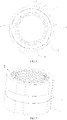
- a motor according to embodiments of the present disclosure is described below with reference to FIGS. 1 to 15 .
- a drive motor includes a motor housing 1 and a stator core 2.
- a rotor (not illustrated) may be disposed in the stator core 2.
- a stator winding (not illustrated) is wound around a stator tooth of the stator core 2, thereby constituting a stator of the drive motor.
- the stator core 2 is mounted in the motor housing 1.
- the motor housing 1 has a fluid inlet 12 and a fluid outlet (not illustrated).
- the fluid outlet is usually defined on an end cover (not illustrated) of the motor housing 1.
- An outer peripheral wall of the stator core 2 has a cut edge 21 extending in an axial direction of the stator core.
- a cooling fluid flow path is formed by a space between the cut edge 21 and an inner peripheral wall of the motor housing 1.
- the fluid inlet 12 and the fluid outlet are in communication with the cooling fluid flow path.
- a stator groove 22 is defined on the outer peripheral wall of the stator core 2 and extends in the axial direction of the stator core 2.
- the stator groove 22 is in communication with the fluid inlet 12 and the fluid outlet.
- a part of the cooling fluid flow path is defined by an inner peripheral wall surface of the motor housing 1 and the stator groove 22.
- the inventor has found through research that, as illustrated in FIG. 9 , as the coefficient k l gradually increases, the pressure drop of the cooling fluid increases (i.e., the flow resistance of the cooling fluid increases), and a temperature rise of the motor decreases. Moreover, when k l is in a range of 0 to 0.05, the pressure drop of the cooling fluid increases faster. When k l is greater than 0.1, the pressure drop of the cooling fluid increases, but reduction of the temperature rise of the motor remains substantially unchanged.
- the depth a of the stator groove 22 is greater than or equal to 1.5 millimeters and smaller than or equal to 2.5 millimeters.
- the inventor has found that when the depth a of the stator groove is 1 mm, electromagnetic performance of the motor is reduced by 0.67%. When the depth a of the stator groove is 2 mm, the electromagnetic performance of the motor is reduced by 1.5%. When the depth a of the stator groove is 3 mm, the electromagnetic performance is reduced by 4.83%.
- the depth a of the stator groove 22 is preferably 2 mm.
- a width a of the stator groove 22 is preferably 1 mm.
- a plurality of stator grooves 22 is divided into a plurality of groups of stator grooves 22, and the plurality of groups of stator grooves 22 is evenly arranged at intervals in the circumferential direction of the stator core 2.
- a central angle ⁇ 1 corresponding to a spacing between adjacent groups of stator grooves ranges from 1 degree to 5 degrees.
- the plurality of stator grooves 22 is divided into first groove groups 221 and second groove groups 222.
- the cut edge 21 is located in the second groove groups 222.
- the first groove groups 221 and the second groove groups 222 are arranged alternately in the circumferential direction of the stator core 2, and are distributed at intervals.
- Each of the second groove groups 222 includes a first section 2221 and a second section 2222.
- the first section 2221 is close to the first groove group 221, and the second section 2222 is close to the cut edge 21.
- the number of the stator grooves 22 of the first section 2221 is greater than the number of the stator grooves 22 of the second section 2222.
- each of the second groove groups 222 has two first sections 2221 and two second sections 2222.
- a central angle ⁇ 32 corresponding to a spacing between a first section 2221 and a second section 2222 adjacent to the first section 2221 ranges from 1 degree to 5 degrees.
- a central angle ⁇ 42 corresponding to a spacing between stator grooves 22 of each section ranges from 0.5 degree to 2 degrees.
- a central angle ⁇ 52 corresponding to each of the stator grooves 22 ranges from 0.5 degree to 2 degrees.
- each of the first groove groups is divided into a plurality of sets.
- FIG. 8 shows two sets.
- Each of the plurality of sets includes a plurality of sections, and FIG. 8 illustrates three sections.
- a central angle ⁇ 21 corresponding to a spacing between adjacent sets ranges from 1 degree to 5 degrees.
- a central angle ⁇ 31 corresponding to a spacing between adjacent sections of each of the plurality of sets ranges from 1 degree to 5 degrees.
- a central angle ⁇ 41 corresponding to a spacing between stator grooves 22 of each of the plurality of sections of each of the plurality of sets ranges from 0.5 degree to 2 degrees.
- a central angle ⁇ 51 corresponding to each of the stator grooves 22 ranges from 0.5 degree to 2 degrees.
- a central angle corresponding to the cut edge 21 is 23 degrees.
- a plurality of fluid inlets is spirally distributed along the motor housing.
- the inventor has found through research that the closer to the fluid inlets 12, the better the cooling effect. Therefore, by arranging the plurality of the fluid inlets 12, cooling capacity of the cooling fluid can be enhanced, and the heat dissipation effect of the motor can be improved.
- the plurality of the fluid inlets 12 is arranged at intervals in an axial direction of the motor housing 1. That is, the plurality of fluid inlets 12 is arranged at intervals along a circumferential direction of the motor housing 1, and is further arranged at intervals in the axial direction of the motor housing 1. For example, the plurality of fluid inlets 12 is spirally distributed on the motor housing 1.
- a housing groove 11 is defined on the inner peripheral wall of the motor housing 1, and extends in the circumferential direction of the motor housing.
- the fluid inlets 12 and the fluid outlet are in communication with the housing groove 11.
- the housing groove 11 is formed as a part of the cooling fluid flow path. Thus, the cooling effect is further improved.
- a plurality of fluid inlets 12 is provided and distributed in the circumferential direction of the motor housing 1.
- an included angle ⁇ between central axes of the adjacent fluid inlets 12 is smaller than or equal to 180 degrees.
- a central angle ⁇ between a projection of a center of each fluid inlet 12 and a projection of a center of a cut edge 21 closest to the fluid inlet 21 on a cross section of the stator core 2 ranges from 0 degree to 5 degrees.
- the central angle ⁇ refers to that an included angle between a projection of a connecting line between the center of each fluid inlet and a circle center of the stator core 2 and a projection of a connecting line between a midpoint of the cut edge 21 closest to the fluid inlet 12 and the circle center of the stator core 2 on the cross section of the stator core 2, and the included angle ranges from 0 degree to 5 degrees.
- a horizontal axis is the central angle ⁇
- a left vertical axis is the pressure drop
- a right vertical axis is the maximum temperature rise ⁇ T of the motor.
- the inventor has found through research that when the central angle ⁇ gradually increases from 0 degree to 5 degrees, increasing rate of the pressure drop (illustrated by a curve indicated by a solid line) and increasing rate of the maximum temperature rise (illustrated by a curve indicated by a dotted line) of the motor are slower (slopes of two curves are small).
- the central angle ⁇ gradually increases from 5 degrees, the increasing rates of the pressure drop and the maximum temperature rise of the motor is obviously accelerated (the slopes of the two curves increase). That is, the thermal performance of the motor is poor. Therefore, it is beneficial for the central angle between the projection of the center of the fluid inlet 12 and the projection of the center of the cut edge 21 closest to the fluid inlet on the cross section of the stator core 2 to range from 0 degree to 5 degrees.
- the central angle between the projection of the center of each fluid inlet 12 and the projection of the center of the cut edge 21 closest to the fluid inlet 21 on the cross section of the stator core 2 is ⁇ , which is preferably 0 degree.
- ⁇ which is preferably 0 degree.
- four cut edges 21 and four fluid inlets 12 are provided.
- the central angle ⁇ between the projection of the center of each fluid inlet 12 and the projection of the center of the cut edge 21 closest to the fluid inlet 21 on the cross section of the stator core 2 is 0 degree.
- the number of the fluid inlets is smaller than the number of the cut edges, and each of the fluid inlets corresponds to one cut edge.
- the stator core 2 is formed by stacking stator laminations.
- the stator laminations are usually made of a silicon steel sheet.
- At least one stator circumferential groove 23 is defined on the outer peripheral wall of the stator core 2, and extends in the circumferential direction of the stator core 2.
- a stator core segment where the stator circumferential groove 23 is located is referred to as a groove core segment.
- the remaining stator core segments are referred to as non-groove core segments.
- the number of the groove core segments is the same as the number of the stator circumferential grooves 23.
- stator circumferential groove 23 By providing the stator circumferential groove 23, it is possible to increase the contact area between the cooling fluid and the stator core 2, and improve the heat dissipation efficiency. Further, the material for manufacturing the stator core can be saved, and the cost of the raw material can be effectively reduced.
- one groove core segment and two non-groove core segments are provided, and the stator groove 22 in communication with the stator circumferential groove 23 are defined on an outer peripheral wall of each of the two non-groove core segments.
- one groove core segment and two non-groove core segments are provided, and the cut edge 21 is disposed on the outer peripheral wall of each of the two non-groove core segments.
- one groove core segment and two non-groove core segments are provided, and both the stator groove 22 and the cut edge 21 are disposed on the outer peripheral wall of each of the two non-groove core segments.
- One or more groove core segments may be provided, and the present disclosure is not limited herein.
- one groove core segment is in communication with the fluid inlet 12. That is, one stator circumferential groove is in communication with the fluid inlet 12.
- the groove core segment is located at an axial middle position of the stator core 2.
- a central axis of the fluid inlet 12 is located in a central cross section of the one groove core segment.
- the groove core segment is in communication with the fluid inlet 12.
- the stator circumferential groove 23 at the groove core segment is filled with the cooling fluid firstly.
- the cooling fluid is brought into in full contact with the outer peripheral wall of the stator core 2 through the stator grooves 22 and the cut edge 21, and is finally discharged through the fluid outlet 13.
- the cooling fluid flows from a middle position towards two ends.
- the cooling fluid can be quickly in total contact with the stator core 2 to dissipate the heat.
- the heat dissipation efficiency can be improved.
- a drive system in a second aspect, includes a decelerator, a controller, and the drive motor as described above.
- the decelerator is connected to a motor shaft of the drive motor.
- the controller is connected to the drive motor.
- a vehicle in a third aspect, includes the drive motor according to the embodiments of the present disclosure.
- the vehicle may be a new energy vehicle.
- the new energy vehicle includes a pure electric vehicle, an extended-range electric vehicle, a hybrid vehicle, a fuel cell electric vehicle, a hydrogen engine vehicle, and the like.
- first and second are only used for descriptive purposes, and cannot be understood as indicating or implying relative importance or implicitly indicating the number of indicated technical features. Therefore, the features associated with “first” and “second” may explicitly or implicitly include at least one of the features. In the description of the present disclosure, “plurality” means at least two, such as two, three, etc., unless otherwise specifically defined.
Landscapes
- Engineering & Computer Science (AREA)
- Power Engineering (AREA)
- Iron Core Of Rotating Electric Machines (AREA)
Applications Claiming Priority (5)
| Application Number | Priority Date | Filing Date | Title |
|---|---|---|---|
| CN202010771190.2A CN114069971B (zh) | 2020-08-03 | 2020-08-03 | 驱动电机、具有该驱动电机的驱动系统和车辆 |
| CN202021586557.5U CN212695852U (zh) | 2020-08-03 | 2020-08-03 | 驱动电机、具有该驱动电机的驱动系统和车辆 |
| CN202021586558.XU CN213185796U (zh) | 2020-08-03 | 2020-08-03 | 用于车辆的驱动电机、驱动系统和车辆 |
| CN202010768996.6A CN114069915B (zh) | 2020-08-03 | 2020-08-03 | 车用驱动电机和车辆 |
| PCT/CN2021/110150 WO2022028381A1 (zh) | 2020-08-03 | 2021-08-02 | 驱动电机、具有该驱动电机的驱动系统和车辆 |
Publications (2)
| Publication Number | Publication Date |
|---|---|
| EP4131744A1 true EP4131744A1 (de) | 2023-02-08 |
| EP4131744A4 EP4131744A4 (de) | 2023-09-06 |
Family
ID=80119994
Family Applications (1)
| Application Number | Title | Priority Date | Filing Date |
|---|---|---|---|
| EP21853343.8A Pending EP4131744A4 (de) | 2020-08-03 | 2021-08-02 | Antriebsmotor, antriebssystem mit diesem antriebsmotor und fahrzeug |
Country Status (3)
| Country | Link |
|---|---|
| US (1) | US20230187999A1 (de) |
| EP (1) | EP4131744A4 (de) |
| WO (1) | WO2022028381A1 (de) |
Families Citing this family (2)
| Publication number | Priority date | Publication date | Assignee | Title |
|---|---|---|---|---|
| US12431767B2 (en) * | 2022-11-02 | 2025-09-30 | Dana Belgium N.V. | Electric machine with a cooling assembly |
| DE102023122696A1 (de) * | 2023-08-24 | 2025-02-27 | Valeo Eautomotive Germany Gmbh | Statoranordnung für eine elektrische Maschine mit vereinfachter Montage des Statorblechpakets im Statorgehäuse |
Family Cites Families (9)
| Publication number | Priority date | Publication date | Assignee | Title |
|---|---|---|---|---|
| JP5042178B2 (ja) * | 2008-09-22 | 2012-10-03 | 三菱電機株式会社 | 電動機の固定子及び電動機及び圧縮機 |
| CN204243921U (zh) * | 2014-11-20 | 2015-04-01 | 上海日立电器有限公司 | 一种压缩机用电机定子外形结构 |
| CN106300853B (zh) * | 2016-08-12 | 2019-06-21 | 合肥国轩高科动力能源有限公司 | 一种电动汽车用永磁同步电机定子 |
| CN206575298U (zh) * | 2017-03-01 | 2017-10-20 | 上海英磁新能源科技有限公司 | 一种用于冷却电机定子的系统 |
| CN110663160B (zh) * | 2017-05-25 | 2022-08-19 | 三菱电机株式会社 | 电动机、压缩机及空气调节装置 |
| CN212909262U (zh) * | 2020-08-03 | 2021-04-06 | 安徽威灵汽车部件有限公司 | 电机和车辆 |
| CN213185796U (zh) * | 2020-08-03 | 2021-05-11 | 安徽威灵汽车部件有限公司 | 用于车辆的驱动电机、驱动系统和车辆 |
| CN212695852U (zh) * | 2020-08-03 | 2021-03-12 | 安徽威灵汽车部件有限公司 | 驱动电机、具有该驱动电机的驱动系统和车辆 |
| CN213243760U (zh) * | 2020-08-03 | 2021-05-18 | 安徽威灵汽车部件有限公司 | 油冷电机和车辆 |
-
2021
- 2021-08-02 EP EP21853343.8A patent/EP4131744A4/de active Pending
- 2021-08-02 WO PCT/CN2021/110150 patent/WO2022028381A1/zh not_active Ceased
-
2023
- 2023-01-11 US US18/095,734 patent/US20230187999A1/en not_active Abandoned
Also Published As
| Publication number | Publication date |
|---|---|
| EP4131744A4 (de) | 2023-09-06 |
| WO2022028381A1 (zh) | 2022-02-10 |
| US20230187999A1 (en) | 2023-06-15 |
Similar Documents
| Publication | Publication Date | Title |
|---|---|---|
| CN212695852U (zh) | 驱动电机、具有该驱动电机的驱动系统和车辆 | |
| US12191752B2 (en) | Motor and vehicle | |
| CN114598051A (zh) | 用于车辆的电机及车辆 | |
| CN112636499A (zh) | 油冷定子、电机、电驱动桥和汽车 | |
| CN115735319A (zh) | 利用轴向冷却剂通道的马达冷却系统 | |
| US20230187999A1 (en) | Drive motor, drive system having drive motor and vehicle | |
| EP1976095A2 (de) | Elektrische Rotationsmaschine und ihr Rotor | |
| CN115917934A (zh) | 利用轴向冷却剂通道的马达冷却系统 | |
| CN212588185U (zh) | 电机机壳、电机和具有该电机的车辆 | |
| CN114598052A (zh) | 用于车辆的电机及车辆 | |
| CN115702538A (zh) | 向轴向冷却剂通道供应冷却剂的定子集成的歧管组件 | |
| CN213185796U (zh) | 用于车辆的驱动电机、驱动系统和车辆 | |
| CN213879402U (zh) | 油冷定子、电机、电驱动桥和汽车 | |
| CN114069915B (zh) | 车用驱动电机和车辆 | |
| EP4611222A1 (de) | Effizienter ölgekühlter motor | |
| AU2022445971A1 (en) | Outer rotor permanent magnet roller stator and stator assembly thereof | |
| US20240275223A1 (en) | Stator and electric motor including the same | |
| CN114069934A (zh) | 电机机壳、电机和具有该电机的车辆 | |
| CN114069971B (zh) | 驱动电机、具有该驱动电机的驱动系统和车辆 | |
| CN113178966A (zh) | 电机通风槽结构、定子及电机 | |
| CN218633479U (zh) | 带有径向通风结构的定子及轮毂电机 | |
| CN220210038U (zh) | 定子冲片、定子组件、电机以及车辆 | |
| EP4738655A1 (de) | Elektromotor und fahrzeug mit dem elektromotor | |
| US12249868B2 (en) | Rotating electric machine | |
| CN220210047U (zh) | 定子组件、电机和车辆 |
Legal Events
| Date | Code | Title | Description |
|---|---|---|---|
| STAA | Information on the status of an ep patent application or granted ep patent |
Free format text: STATUS: THE INTERNATIONAL PUBLICATION HAS BEEN MADE |
|
| PUAI | Public reference made under article 153(3) epc to a published international application that has entered the european phase |
Free format text: ORIGINAL CODE: 0009012 |
|
| STAA | Information on the status of an ep patent application or granted ep patent |
Free format text: STATUS: REQUEST FOR EXAMINATION WAS MADE |
|
| 17P | Request for examination filed |
Effective date: 20221026 |
|
| AK | Designated contracting states |
Kind code of ref document: A1 Designated state(s): AL AT BE BG CH CY CZ DE DK EE ES FI FR GB GR HR HU IE IS IT LI LT LU LV MC MK MT NL NO PL PT RO RS SE SI SK SM TR |
|
| A4 | Supplementary search report drawn up and despatched |
Effective date: 20230804 |
|
| RIC1 | Information provided on ipc code assigned before grant |
Ipc: H02K 5/15 20060101ALI20230731BHEP Ipc: H02K 5/20 20060101ALI20230731BHEP Ipc: H02K 1/20 20060101ALI20230731BHEP Ipc: H02K 9/19 20060101AFI20230731BHEP |
|
| DAV | Request for validation of the european patent (deleted) | ||
| DAX | Request for extension of the european patent (deleted) | ||
| STAA | Information on the status of an ep patent application or granted ep patent |
Free format text: STATUS: EXAMINATION IS IN PROGRESS |
|
| 17Q | First examination report despatched |
Effective date: 20231123 |