EP4131746A1 - Rotorherstellungsverfahren - Google Patents
Rotorherstellungsverfahren Download PDFInfo
- Publication number
- EP4131746A1 EP4131746A1 EP20927127.9A EP20927127A EP4131746A1 EP 4131746 A1 EP4131746 A1 EP 4131746A1 EP 20927127 A EP20927127 A EP 20927127A EP 4131746 A1 EP4131746 A1 EP 4131746A1
- Authority
- EP
- European Patent Office
- Prior art keywords
- shaft
- peripheral surface
- providing
- rotor core
- rotor
- Prior art date
- Legal status (The legal status is an assumption and is not a legal conclusion. Google has not performed a legal analysis and makes no representation as to the accuracy of the status listed.)
- Pending
Links
Images



Classifications
-
- H—ELECTRICITY
- H02—GENERATION; CONVERSION OR DISTRIBUTION OF ELECTRIC POWER
- H02K—DYNAMO-ELECTRIC MACHINES
- H02K15/00—Processes or apparatus specially adapted for manufacturing, assembling, maintaining or repairing of dynamo-electric machines
- H02K15/02—Processes or apparatus specially adapted for manufacturing, assembling, maintaining or repairing of dynamo-electric machines of stator or rotor bodies
- H02K15/03—Processes or apparatus specially adapted for manufacturing, assembling, maintaining or repairing of dynamo-electric machines of stator or rotor bodies having permanent magnets
-
- H—ELECTRICITY
- H02—GENERATION; CONVERSION OR DISTRIBUTION OF ELECTRIC POWER
- H02K—DYNAMO-ELECTRIC MACHINES
- H02K1/00—Details of the magnetic circuit
- H02K1/06—Details of the magnetic circuit characterised by the shape, form or construction
- H02K1/22—Rotating parts of the magnetic circuit
- H02K1/28—Means for mounting or fastening rotating magnetic parts on to, or to, the rotor structures
-
- H—ELECTRICITY
- H02—GENERATION; CONVERSION OR DISTRIBUTION OF ELECTRIC POWER
- H02K—DYNAMO-ELECTRIC MACHINES
- H02K15/00—Processes or apparatus specially adapted for manufacturing, assembling, maintaining or repairing of dynamo-electric machines
- H02K15/02—Processes or apparatus specially adapted for manufacturing, assembling, maintaining or repairing of dynamo-electric machines of stator or rotor bodies
- H02K15/028—Fastening stator or rotor bodies to casings, supports, shafts or hubs
-
- Y—GENERAL TAGGING OF NEW TECHNOLOGICAL DEVELOPMENTS; GENERAL TAGGING OF CROSS-SECTIONAL TECHNOLOGIES SPANNING OVER SEVERAL SECTIONS OF THE IPC; TECHNICAL SUBJECTS COVERED BY FORMER USPC CROSS-REFERENCE ART COLLECTIONS [XRACs] AND DIGESTS
- Y10—TECHNICAL SUBJECTS COVERED BY FORMER USPC
- Y10T—TECHNICAL SUBJECTS COVERED BY FORMER US CLASSIFICATION
- Y10T29/00—Metal working
- Y10T29/49—Method of mechanical manufacture
- Y10T29/49002—Electrical device making
- Y10T29/49009—Dynamoelectric machine
- Y10T29/49012—Rotor
Definitions
- the present invention relates to rotor manufacturing methods.
- a rotor manufacturing method known in the related art involves fixing a shaft to an inner peripheral surface of a rotor core.
- Such an armature is disclosed, for example, in Japanese Unexamined Patent Application Publication No. 2001-268858 ( JP 2001-268858 A ).
- JP 2001-268858 A discloses a method for manufacturing a motor rotor including: a hollow rotary shaft having a pipe structure; and a laminated core whose inner peripheral surface has the rotary shaft fixed thereto.
- the manufacturing method involves placing the rotary shaft having constant outside diameter, inside diameter, and thickness, such that the rotary shaft is located radially inward of the laminated core. With portions of the rotary shaft exposed externally, the rotary shaft is fixed to a forming die of a hydroformer.
- the manufacturing method then involves performing a hydroforming process to increase the internal pressure of the rotary shaft by injecting a liquid into an entire internal space of the rotary shaft.
- a portion of the rotary shaft facing the laminated core is expanded (or plastically deformed) and thus fixed to the laminated core.
- the externally exposed portions of the rotary shaft are expanded beyond the inside diameter of the laminated core so as to provide disconnection stoppers.
- the number of disconnection stoppers provided is two such that the laminated core is interposed between the disconnection stoppers in an axial direction of the laminated core.
- Patent Document 1 JP 2001-268858 A
- a bearing member is usually placed to support the rotary shaft such that the rotary shaft is rotatable.
- the dimensional accuracy of a portion of the rotary shaft around which the bearing member is to be placed presumably needs to be higher than the dimensional accuracy of a portion of the rotary shaft to be fixed to a laminated core.
- a portion of the rotary shaft around which a bearing member is to be placed is presumably located axially outward of the disconnection stoppers.
- the motor rotor manufacturing method disclosed in JP 2001-268858 A involves performing a hydroforming process to increase the internal pressure of the rotary shaft by injecting a liquid into the entire internal space of the rotary shaft, with the rotary shaft (which has constant outside diameter, inside diameter, and thickness) located radially inward of the laminated core.
- the portion of the rotary shaft facing the laminated core is expanded (or plastically deformed) and thus fixed to the laminated core. Accordingly, when the portion of the rotary shaft facing the laminated core is fixed to the laminated core, an internal pressure produced by the liquid is applied also to the portion of the rotary shaft around which the bearing member is to be placed.
- Conceivable measures to prevent a decrease in the dimensional accuracy of the portion of the rotary shaft around which the bearing member is to be placed include increasing the radial thickness of an entirety of the rotary shaft so as to enhance the rigidity of the entirety of the rotary shaft.
- enhancing the rigidity of the entirety of the rotary shaft may make it unlikely that the portion of the rotary shaft around which the bearing member is to be placed will plastically deform.
- An increase in the radial thickness of the entirety of the rotary shaft may require an increase in hydroformer-produced pressure necessary to expand the rotary shaft such that the portion of the rotary shaft facing the laminated core is fixed to the laminated core.
- the hydroformer (or a rotor manufacturing apparatus) unfortunately increases in size in order to prevent a decrease the dimensional accuracy of the portion of the rotary shaft (or a shaft) around which the bearing member is to be placed, i.e., a portion of the rotary shaft located on one side in a rotation axis direction relative to a shaft insertion hole.
- This invention has been made to solve the problems mentioned above, and an object of this invention is to provide a rotor manufacturing method that would be able to prevent a decrease in the dimensional accuracy of a portion of a shaft located on one side in a rotation axis direction relative to a shaft insertion hole while keeping a rotor manufacturing apparatus from increasing in size, if the method involves performing hydroforming.
- a rotor manufacturing method involves fixing a shaft to an inner peripheral surface of a shaft insertion hole of a rotor core including a plurality of annular electromagnetic steel sheets stacked in a rotation axis direction such that the shaft insertion hole is defined.
- the rotor manufacturing method includes the steps of: providing the shaft having a cylindrical shape in which an inside diameter of a first portion of the shaft to be placed on the inner peripheral surface of the shaft insertion hole is larger than an inside diameter of a second portion of the shaft located on one side in the rotation axis direction relative to the first portion; inserting the shaft into the shaft insertion hole by axially moving at least one of the shaft and the rotor core such that an outer periphery of the first portion of the shaft radially faces the inner peripheral surface of the shaft insertion hole; and fixing the shaft to the rotor core by a hydroforming process that involves filling an internal space of the shaft with a fluid and expanding the shaft with an internal pressure produced by the fluid, thus pressure-welding the first portion to the inner peripheral surface of the shaft insertion hole after the step of inserting the shaft.
- ⁇ ⁇ P ⁇ D / t
- P denotes a pressure (internal pressure)
- D denotes an inside diameter
- t denotes a thickness
- the circumferential stress ⁇ ⁇ applied to the shaft has a tendency to increase as the inside diameter D increases and to decrease as the inside diameter D decreases.
- the inventors of the present application have developed the rotor manufacturing method according to the above aspect, which includes the step of providing the shaft having a cylindrical shape in which the inside diameter of the first portion of the shaft to be placed on the inner peripheral surface of the shaft insertion hole is larger than the inside diameter of the second portion of the shaft located on one side in the rotation axis direction relative to the first portion.
- the inside diameter of the first portion is larger than the inside diameter of the second portion, a circumferential stress applied to the first portion of the shaft will be greater than a circumferential stress applied to the second portion accordingly.
- the same internal pressure is applied to the first portion and the second portion, which makes it likely that the first portion having a relatively large inside diameter will expand (or deform) to a greater degree than the second portion.
- the second portion having a relatively small inside diameter is unlikely to deform (or plastically deform) to a greater degree than the first portion.
- the rotor manufacturing method is able to make the second portion less prone to deform without increasing the radial thickness of an entirety of the shaft. Consequently, if the rotor manufacturing method involves performing hydroforming, the rotor manufacturing method would be able to prevent a decrease in the dimensional accuracy of the second portion (which is a portion of the shaft located on one side in the rotation axis direction relative to the shaft insertion hole) while keeping a rotor manufacturing apparatus from increasing in size.
- the present invention would be able to prevent a decrease in the dimensional accuracy of a portion of a shaft located on one side in a rotation axis direction relative to a shaft insertion hole while keeping a rotor manufacturing apparatus from increasing in size, if hydroforming is to be performed.
- the rotor 100 is combined with a stator (not illustrated) so as to provide a rotary electric machine.
- axial direction and “rotation axis direction” each refer to a direction along a rotation axis (which is denoted by the reference sign C1 and corresponds to a direction Z1 and a direction Z2) of the rotor 100 (see FIG 1 ).
- radially inward refers to a direction (i.e., a direction R1) toward the rotation axis C1 of the rotor 100.
- radially outward refers to a direction (i.e., a direction R2) outward from the rotor 100.
- circumferential direction refers to a circumferential direction (i.e., a direction A1 and a direction A2) of the rotor 100 as illustrated in FIG 2 .
- the rotor 100 includes a rotor core 10, a shaft 20, and bearing members 31 and 32.
- the rotor core 10 includes a plurality of electromagnetic steel sheets 11 stacked in an axial direction such that a hole 11a is defined therein.
- the electromagnetic steel sheets 11 are, for example, silicon steel plates.
- the rotor core 10 has a cylindrical shape whose central axis corresponds to the rotation axis C1. Surfaces of the electromagnetic steel sheets 11 that define an inner peripheral surface 12 of the rotor core 10 (i.e., an inner peripheral surface 12 of the hole 11a) are substantially flush with each other in the axial direction. Surfaces of the electromagnetic steel sheets 11 that define an outer peripheral surface 13 of the rotor core 10 are substantially flush with each other in the axial direction.
- the hole 11a is an example of a "shaft insertion hole" in the claims.
- the shaft 20 has a cylindrical shape whose central axis corresponds to the rotation axis C1.
- the shaft 20 is made of, for example, carbon steel.
- the shaft 20 is fixed to the inner peripheral surface 12 of the rotor core 10.
- the shaft 20 includes a first portion 40 and second portions 50 and 60.
- the first portion 40 and the second portions 50 and 60 each have a cylindrical shape.
- the first portion 40 is an axially central portion of the shaft 20 placed on the inner peripheral surface 12 of the rotor core 10. Specifically, an outer peripheral surface 41 of the first portion 40 is in abutment with the inner peripheral surface 12 of the rotor core 10. In the first embodiment, the first portion 40 is pressure-welded to the inner peripheral surface 12 of the hole 11a by hydroforming.
- the first portion 40 has an inside diameter D1, an outside diameter D11, and a thickness t1.
- the inside diameter D1, the outside diameter D11, and the thickness t1 are each substantially constant.
- An inner peripheral surface 42 of the first portion 40 is located radially outward of an inner peripheral surface 52 of the second portion 50 and an inner peripheral surface 62 of the second portion 60. Accordingly, the inner peripheral surface 42 of the first portion 40 is recessed relative to the inner peripheral surface 52 of the second portion 50 and the inner peripheral surface 62 of the second portion 60.
- the first portion 40 is thus provided with a recess 43 recessed radially outward.
- the recess 43 has the function of temporarily storing a cooling fluid that flows in the axial direction through an internal space of the shaft 20 during use of the rotor 100.
- the cooling fluid may be an automatic transmission fluid (ATF).
- ATF automatic transmission fluid
- the second portion 50 is a portion of the shaft 20 located in the direction Z1 relative to the first portion 40.
- the second portion 60 is a portion of the shaft 20 located in the direction Z2 relative to the first portion 40.
- the second portion 50 is a portion of the shaft 20 around which the bearing member 31 is placed.
- the second portion 60 is a portion of the shaft 20 around which the bearing member 32 is placed.
- the second portions 50 and 60 each have an inside diameter D2, an outside diameter D12, and a thickness t2.
- the inside diameter D2, the outside diameter D12, and the thickness t2 are each substantially constant.
- the inside diameter D1 is larger than the inside diameter D2
- the outside diameter D11 is larger than the outside diameter D12.
- the thickness t1 of the first portion 40 is substantially equal to the thickness t2 of each of the second portions 50 and 60.
- a step portion 71 is provided between the outer peripheral surface 41 of the first portion 40 and an outer peripheral surface 51 of the second portion 50.
- a step portion 72 is provided between the outer peripheral surface 41 of the first portion 40 and an outer peripheral surface 61 of the second portion 60.
- the step portion 71 defines a recess recessed radially inward from the outer peripheral surface 41 of the first portion 40 to the outer peripheral surface 51 of the second portion 50.
- the step portion 71 includes a surface 71a parallel to a direction perpendicular to the axial direction.
- the step portion 72 defines a recess recessed radially inward from the outer peripheral surface 41 of the first portion 40 to the outer peripheral surface 61 of the second portion 60.
- the step portion 72 includes a surface 72a parallel to a direction perpendicular to the axial direction.
- the bearing member 31 is placed such that the bearing member 31 circumferentially surrounds the outer peripheral surface 51 of the second portion 50 from its radially outer side and is in contact with the surface 71a of the step portion 71.
- the bearing member 32 is placed such that the bearing member 32 circumferentially surrounds the outer peripheral surface 61 of the second portion 60 from its radially outer side and is in contact with the surface 72a of the step portion 72.
- the bearing members 31 and 32 support the shaft 20 and the rotor core 10 such that the shaft 20 and the rotor core 10 are rotatable around the rotation axis C1.
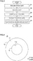
- FIG 3 is a flow chart illustrating steps for manufacturing the rotor 100.
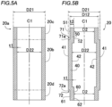
- step S1 involves providing the rotor core 10. Specifically, a strip-shaped electromagnetic steel sheet is stamped into annular shapes in a progressive pressing apparatus (not illustrated), and the resulting electromagnetic steel sheets 11 are stacked in the rotation axis direction such that the hole 11a is defined as illustrated in FIG. 4 .
- This provides the rotor core 10 having an annular shape (or a cylindrical shape).
- the electromagnetic steel sheets 11 identical to each other are stacked on top of each other, and the rotor core 10 is thus provided such that the surfaces of the electromagnetic steel sheets 11, which define the inner peripheral surface 12 of the hole 11a, are flush with each other in the rotation axis direction.
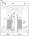
- Step S2 involves providing the shaft 20. Specifically, as illustrated in FIG 5A , step S2 involves preparing a cylindrical pipe member 20a having the thickness 11, an outside diameter D21, and an inside diameter D22. In other words, step S2 involves preparing the pipe member 20a, with the outer peripheral surface 41 of the first portion 40, the outer peripheral surface 51 of the second portion 50, and the outer peripheral surface 61 of the second portion 60 flush with each other.
- the outside diameter D21 is smaller than the outside diameter D11 by a clearance CL1 (which will be described below).
- the inside diameter D22 is smaller than the inside diameter D1 by the clearance CL1 (which will be described below).
- a surface 20b of the pipe member 20a which will be the outer peripheral surface 41 of the first portion 40
- a surface 20c of the pipe member 20a which will be the outer peripheral surface 51 of the second portion 50
- the pipe member 20a in this state is placed in a drawing apparatus (not illustrated) and subjected to drawing such that the surface 20c deforms radially inward.
- This provides the shaft 20 having a cylindrical shape in which the outside diameter D21 of the first portion 40 is larger than the outside diameter D12 of the second portion 50 as illustrated in FIG 5B .
- the shaft 20 is further subjected to drawing such that a surface 20d, which will be the outer peripheral surface 61 of the second portion 60, deforms radially inward similarly to the surface 20c.
- a surface 20d which will be the outer peripheral surface 61 of the second portion 60, deforms radially inward similarly to the surface 20c.
- This causes the resulting shaft 20 to have a cylindrical shape in which the inside diameter D22 of the first portion 40 is larger than the inside diameter D2 of each of the second portions 50 and 60.
- the radial thickness t1 of the first portion 40 is equal to or smaller than the radial thickness t2 of the second portion 50. In the first embodiment, the thickness t1 is equal to the thickness t2.
- the pipe member 20a to drawing provides the step portion 71 between the outer peripheral surface 41 of the first portion 40 and the outer peripheral surface 51 of the second portion 50, and provides the step portion 72 between the outer peripheral surface 41 of the first portion 40 and the outer peripheral surface 61 of the second portion 60.
- the step portion 71 defines a recess recessed radially inward from the outer peripheral surface 41 of the first portion 40 to the outer peripheral surface 51 of the second portion 50, and includes the surface 71a parallel to a direction perpendicular to the axial direction.
- the step portion 72 defines a recess recessed radially inward from the outer peripheral surface 41 of the first portion 40 to the outer peripheral surface 61 of the second portion 60, and includes the surface 72a parallel to a direction perpendicular to the axial direction.
- Step S3 involves inserting the shaft 20 into the hole 11a.
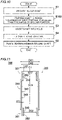
- the rotor core 10 is placed in a hydroformer 200 such that an end face 15 of the rotor core 10 comes into contact with an upper surface 211 of a lower die 210 of the hydroformer 200.
- the shaft 20 is placed over the hole 11a of the rotor core 10 (or placed in the direction Z1 relative to the hole 11a) and is then moved downward (or in the direction Z2) with respect to the rotor core 10.
- the shaft 20 is thus inserted into the hole 11a.
- the outer peripheral surface 41 of the first portion 40 of the shaft 20 radially faces the inner peripheral surface 12 of the rotor core 10, with the clearance CL1 left therebetween.
- a lifter 220 is placed radially inward of the lower die 210.
- the shaft 20 is placed on an upper surface 221 of the lifter 220 of the hydroformer 200. This brings a lower end face 21 of the shaft 20 into contact with the upper surface 221 of the lifter 220.
- Step S4 involves fixing the shaft 20 to the rotor core 10.
- the shaft 20 is fixed to the inner peripheral surface 12 of the hole 11a of the rotor core 10 including the annular electromagnetic steel sheets 11 stacked in the rotation axis direction such that the hole 11a is defined.
- the shaft 20 is fixed to the rotor core 10 by hydroforming that involves filling the internal space of the shaft 20 with a fluid L (see FIG 9 ) and expanding the shaft 20 with a pressure (internal pressure) P produced by the fluid L, thus pressure-welding the first portion 40 to the inner peripheral surface 12 of the hole 11a.
- a pressing member 230 and a seal punch member 240 of the hydroformer 200 are placed above the rotor core 10 and the shaft 20.
- the pressing member 230 has a cylindrical shape.
- the seal punch member 240 has a columnar shape.
- the seal punch member 240 is placed radially inward of the pressing member 230.
- the pressing member 230 and the seal punch member 240 are then both moved downward with respect to the rotor core 10 and the shaft 20.
- a lower surface 231 of a radially inward portion of the pressing member 230 thus comes into contact with the surface 71a of the step portion 71 of the shaft 20.
- a lower surface 241 of the seal punch member 240 comes into contact with an upper end face 22 of the shaft 20.
- the pressing member 230 is an example of a "die member" in the claims.
- the first embodiment involves fixing the shaft 20 to the rotor core 10 by hydroforming, with the pressing member 230 in contact with both of the step portion 71 and an end face 14 of the rotor core 10 facing in the rotation axis direction.
- moving the pressing member 230 relative to the rotor core 10 and the shaft 20 brings the lower surface 231 of the radially inward portion of the pressing member 230 into contact with the surface 71a of the step portion 71 parallel to the direction perpendicular to the axial direction, and brings a lower surface 232 of a radially outward portion of the pressing member 230 into contact with the end face 14 of the rotor core 10.
- the axial position of the rotor core 10 is thus fixed by the lower die 210 and the pressing member 230.
- the shaft 20 With the axial position of the rotor core 10 fixed by the lower die 210 and the pressing member 230, the shaft 20 is sandwiched between the lifter 220 and the seal punch member 240 in the axial direction.
- moving the lifter 220, the pressing member 230, and the seal punch member 240 downward moves the shaft 20 downward relative to the rotor core 10. Consequently, as illustrated in FIG 8 , the first portion 40 of the shaft 20 radially faces an entirety of the inner peripheral surface 12 of the rotor core 10.
- the hydroformer 200 injects the fluid into the internal space of the shaft 20 (i.e., an internal space of the shaft 20 defined by the inner peripheral surfaces 42, 52, and 62) with a predetermined pressure P so as to pressurize the internal space of the shaft 20.
- the predetermined pressure P is as high as a few or several hundred megapascals at which the first portion 40 of the shaft 20 is plastically deformable and the rotor core 10 is elastically deformed.
- the predetermined pressure P is a pressure at which the shaft 20 is fixable to the rotor core 10.
- the inside diameter D22 of the first portion 40 thus increases to the inside diameter D1 so as to remove the clearance CL1.
- the inside diameter D1 of the first portion 40 is larger than the inside diameter D2 of each of the second portions 50 and 60, it is evident from the relational expression (2) that a circumferential stress ⁇ ⁇ 1 applied to the inner peripheral surface 42 of the first portion 40 will be greater than a circumferential stress ⁇ ⁇ 2 applied to the inner peripheral surface 52 of the second portion 50 and the inner peripheral surface 62 of the second portion 60. Accordingly, the inner peripheral surface 42 of the first portion 40 expands such that its circumferential length increases, resulting in radially outward expansion of the first portion 40. Although the second portion 50 also expands radially outward, the degree of deformation of the second portion 50 is lower than the degree of deformation of the first portion 40.
- Pressing the rotor core 10 radially outward with the first portion 40 causes the rotor core 10 to elastically deform such that the rotor core 10 expands radially outward, and causes the first portion 40 to plastically deform such that the first portion 40 expands radially outward.
- the fluid in the internal space of the shaft 20 is then removed, which causes the rotor core 10 to contract radially inward and return to the shape the rotor core 10 had before its elastic deformation, and causes the second portion 50 to contract radially inward and return to the shape the second portion 50 had before its elastic deformation.
- the plastically deformed first portion 40 is thus pressure-welded (or interference-fitted) to the radially inwardly contracted rotor core 10. Consequently, the shaft 20 is fixed to the rotor core 10 as illustrated in FIG 1 .
- the inner peripheral surface 42 of the first portion 40 remains recessed relative to the inner peripheral surface 52 of the second portion 50 after hydroforming.
- the first portion 40 is provided with the recess 43 after hydroforming.
- the cooling fluid (ATF) flowing axially through the internal space of the shaft 20 is stored in the recess 43, enhancing the ability to cool the rotor core 10.
- the rotor core 10 and the shaft 20 are then removed from the hydroformer 200.
- step S5 involves placing the bearing members 31 and 32 around the shaft 20. Specifically, the bearing member 31 is placed around the outer peripheral surface 51 of the second portion 50, and the bearing member 32 is placed around the outer peripheral surface 61 of the second portion 60. To be more specific, the bearing member 31 is placed in contact with the surface 71a of the step portion 71, and the bearing member 32 is placed in contact with the surface 72a of the step portion 72. This completes the manufacture of the rotor 100. A stator is then placed radially outward of the rotor 100 so as to manufacture a rotary electric machine.
- the method for manufacturing the rotor 300 according to the second embodiment involves providing a shaft 320 in which a thickness 111 of a first portion 340 is smaller than a thickness t12 of each of second portions 350 and 360.
- the manufacturing method according to the second embodiment involves performing step S102 instead of step S2 illustrated in FIG 3 .
- step S102 involves providing the shaft 320.
- step S102 involves providing the shaft 320 including: the first portion 340 having an inside diameter D31, an outside diameter D41, and the thickness t11; and the second portions 350 and 360 each having an inside diameter D32, an outside diameter D42, and the thickness t12.
- the thickness 111 is smaller than the thickness t12.
- the inside diameter D31 is larger than the inside diameter D32.
- the outside diameter D41 is larger than the outside diameter D42.
- An outer periphery 341 of the first portion 340 is located radially outward of an outer periphery 351 of the second portion 350 and radially outward of an outer periphery 361 of the second portion 360.
- the thickness t11 of the first portion 340 is smaller than the thickness t12 of each of the second portions 350 and 360, it is evident from the relational expression (2) that a circumferential stress ⁇ ⁇ 11 applied to an inner peripheral surface 342 of the first portion 340 will be greater than a circumferential stress ⁇ ⁇ 12 applied to an inner peripheral surface 352 of the second portion 350 and an inner peripheral surface 362 of the second portion 360. Accordingly, the inner peripheral surface 342 of the first portion 340 expands such that its circumferential length increases, resulting in radially outward expansion of the first portion 340. The degree of radially outward expansion of the second portion 350 is smaller than the degree of radially outward expansion of the first portion 340.
- Other steps included in the manufacturing method according to the second embodiment are similar to the corresponding steps (i.e., step S1 and steps S3 to S5) included in the manufacturing method according to the first embodiment.
- the first and second embodiments are able to achieve effects described below.
- the manufacturing methods according to the first and second embodiments each include the step (S2, S102) of providing a shaft (20, 320) having a cylindrical shape in which an inside diameter (D1, D31) of a first portion (40, 340) to be placed on the inner peripheral surface (12) of the shaft insertion hole (11a) is larger than an inside diameter (D2, D32) of a second portion (50, 60, 350, 360) located on one side in a rotation axis direction relative to the first portion (40, 340).
- a circumferential stress ( ⁇ ⁇ 1 , ⁇ ⁇ 11 ) applied to the first portion (40, 340) of the shaft (20, 320) will be greater than a circumferential stress ( ⁇ ⁇ 2 , ⁇ ⁇ 12 ) applied to the second portion (50, 60, 350, 360) accordingly.
- the manufacturing methods are able to make the second portion (50, 60, 350, 360) less prone to deform without increasing a radial thickness (t1, t2, t11, t12) of an entirety of the shaft (20, 320). Consequently, if the manufacturing methods involve performing hydroforming, the manufacturing methods would be able to prevent a decrease in the dimensional accuracy of the second portion (50, 60, 350, 360), which is the portion (50, 60) of the shaft (20, 320) located on one side in the rotation axis direction relative to the shaft insertion hole (11a), while keeping a manufacturing apparatus (200) for a rotor (100, 300) from increasing in size.
- the step (S4) of fixing the shaft (20, 320) to the rotor core (10) involves fixing the shaft (20, 320) to the rotor core (10) by the hydroforming process such that an inner peripheral surface (42, 342) of the first portion (40, 340) remains recessed relative to an inner peripheral surface (52, 62, 352, 362) of the second portion (50, 60, 350, 360) after the hydroforming process has been performed.
- This enables a cooling fluid to be stored in a recess (43) of the shaft (20, 320) during use of the rotor (100).
- the cooling fluid stored in the recess (43) is thus able to cool the rotor core (10) through the second portion (50, 60, 350, 360).
- the step (S2, S102) of providing the shaft (20, 320) involves providing the shaft (20, 320) in which a radial thickness (t1, t11) of the first portion (40, 340) is equal to or smaller than a radial thickness (t2, t12) of the second portion (50, 60, 350, 360).
- a radial thickness (t1, t11) of the first portion (40, 340) is equal to or smaller than a radial thickness (t2, t12) of the second portion (50, 60, 350, 360).
- a circumferential stress ( ⁇ ⁇ ) applied to the shaft (20, 320) has a tendency to decrease as a thickness (t) of the shaft (20, 320) increases and to increase as the thickness (t) decreases.
- the manufacturing methods according to the first and second embodiments are able to make the circumferential stress ( ⁇ ⁇ 1 , ( ⁇ ⁇ 11 ), which is applied to the first portion (40, 340), greater than when the radial thickness (t1, t11) of the first portion (40, 340) is larger than the radial thickness (t2, 112) of the second portion (50, 60, 350, 360).
- the manufacturing methods according to the first and second embodiments are thus able to prevent an increase in the internal pressure (P) necessary to expand the first portion (40, 340). Consequently, because the necessary internal pressure (P) is kept from increasing, the manufacturing methods according to the first and second embodiments are able to prevent an increase in the degree of deformation of the second portion (50, 60, 350, 360) accordingly.
- the step (S102) of providing the shaft (320) involves providing the shaft (320) in which the radial thickness (t11) of the first portion (340) is smaller than the radial thickness (t12) of the second portion (350, 360).
- the circumferential stress ( ⁇ ⁇ 11 ) applied to the first portion (340) increases accordingly as indicated by the relational expression (2).
- the first portion (340) is thus expandable by a relatively low internal pressure (P), so that as the necessary internal pressure (P) decreases, the degree of deformation of the second portion (350, 360) further decreases accordingly. Consequently, the manufacturing method according to the second embodiment is able to further increase the dimensional accuracy of the second portion (350, 360).
- the step (S2) of providing the shaft (20) involves providing the shaft (20) in which the radial thickness (t1) of the first portion (40) is equal to the radial thickness (t2) of the second portion (50, 60). This eliminates the need to machine the shaft (20) such that the radial thickness (t1) of the first portion (40) differs from the radial thickness (t2) of the second portion (50, 60). Consequently, the first embodiment is able to prevent an increase in the number of steps for manufacturing the rotor (100).
- the step (S2, S102) of providing the shaft (20, 320) involves providing the shaft (20, 320) having a cylindrical shape in which an outside diameter (D11, D41) of the first portion (40, 340) is larger than an outside diameter (D12, D42) of the second portion (50, 60, 350, 360).
- a pipe member (20a) having constant inside and outside diameters is prepared and deformed such that its first portion (40, 340) expands radially outward or its second portion (50, 60, 350, 360) contracts radially inward.
- the step (S2, S102) of providing the shaft (20, 320) involves providing the shaft (20, 320) having a cylindrical shape in which the outside diameter (D11, D41) of the first portion (40, 340) is larger than the outside diameter (D12, D42) of the second portion (50, 60, 350, 360).
- the shaft (20, 320) includes a step portion (71, 72) defined between the outer periphery (41, 341) of the first portion (40, 340) and an outer periphery (51, 61, 351, 361) of the second portion (50, 60, 350, 360).
- the step (S4) of fixing the shaft (20, 320) to the rotor core (10) involves fixing the shaft (20, 320) to the rotor core (10) by the hydroforming process, with a die member (230) in contact with both of the step portion (71, 72) and an end face (14) of the rotor core (10) facing in the rotation axis direction.
- the manufacturing methods according to the first and second embodiments each further include the step (S5) of placing a bearing member (31, 32) on the step portion (71, 72) after the step (S4) of fixing the shaft (20, 320).
- the die member (230) enables positioning of the rotor core (10) with respect to the step portion (71, 72) on which the bearing member (31, 32) needs to be placed with relatively high dimensional accuracy. Consequently, the manufacturing methods according to the first and second embodiments are able to increase the axial dimensional accuracy of the step portion (71, 72) while increasing the radial dimensional accuracy of the second portion (50, 60, 350, 360).
- the step (S2, S102) of providing the shaft (20, 320) involves performing drawing on a pipe member (20a) in which the outer periphery (41, 341) of the first portion (40, 340) is flush with an outer periphery (51, 61, 351, 361) of the second portion (50, 60, 350, 360), so as to cause the outer periphery (51, 61, 351, 361) of the second portion (50, 60, 350, 360) to deform radially inward, thus providing the shaft (20, 320) having a cylindrical shape in which the outside diameter (D11, D41) of the first portion (40, 340) is larger than the outside diameter (D12, D42) of the second portion (50, 60, 350, 360).
- preparing the pipe member (20a) having constant inside and outside diameters and subjecting the pipe member (20a) to drawing facilitates providing the shaft (20, 320) having a cylindrical shape in which the outside diameter (D11, D41) of the first portion (40, 340) is larger than the outside diameter (D12, D42) of the second portion (50, 60, 350, 360).
- the manufacturing methods according to the first and second embodiments each further include the step (S1) of providing the rotor core (10) such that surfaces of the electromagnetic steel sheets defining the inner peripheral surface (12) of the shaft insertion hole (11a) are flush with each other in the rotation axis direction before the step of inserting the shaft (20, 320).
- the resulting rotor core (10) has a simpler structure than a rotor core (10) having a relatively complicated shape in which surfaces defining an inner peripheral surface (12) of a shaft insertion hole (11a) are not flush with each other. Consequently, the manufacturing methods according to the first and second embodiments are able to facilitate providing the rotor core (10).
- steps S2 and S102 each involve providing the shaft in which the outside diameter of the first portion is larger than the outside diameter of each second portion.
- the present invention is not limited to this example.
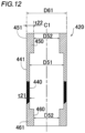
- One variation illustrated in FIG 12 may involve providing a shaft 420 in which an outside diameter D61 of a first portion 440 is substantially equal to an outside diameter D61 of each of second portions 450 and 460.
- a thickness t21 of the first portion 440 is made smaller than a thickness t22 of each of the second portions 450 and 460 by making an inside diameter D51 of the first portion 440 smaller than an inside diameter D52 of each of the second portions 450 and 460.
- Such a variation makes it possible to reduce the degree of deformation of the second portion 450 during fixation of the shaft 420 to the rotor core.
- the first and second embodiments have illustrated an example where the shaft is provided with the step portions.
- the present invention is not limited to this example.
- the variation illustrated in FIG 12 may involve providing the shaft 420 including no step portions such that an outer peripheral surface 441 of the first portion 440 of the shaft 420 is flush with an outer peripheral surface 451 of the second portion 450 and an outer peripheral surface 461 of the second portion 460.
- the first and second embodiments have illustrated an example where the bearing members are placed around the second portions.
- the present invention is not limited to this example.
- resolver(s) may be placed around the second portion(s).
- the first and second embodiments have illustrated an example where the second portion located in the direction Z1 is substantially identical in shape to the second portion located in the direction Z2.
- the present invention is not limited to this example.
- An alternative example may involve providing the second portion located in the direction Z2 such that the radial thickness of the second portion located in the direction Z2 is larger than the radial thickness of the second portion located in the direction Z1.
- the first and second embodiments have illustrated an example where the ATF is allowed to flow through the internal space of the shaft.
- the present invention is not limited to this example.
- An alternative example may involve placing an additional member in the internal space of the shaft.
- the first and second embodiments have illustrated an example where the manufacturing methods each involve performing drawing in providing the shaft having a cylindrical shape in which the outside diameter of the first portion is larger than the outside diameter of each second portion.
- the present invention is not limited to this example.
- An alternative example may involve cutting the outer peripheral surface of each second portion, thus providing the shaft having a cylindrical shape in which the outside diameter of the first portion is larger than the outside diameter of each second portion.
- the first and second embodiments have illustrated an example where the manufacturing methods each involve providing the rotor core such that surfaces of the electromagnetic steel sheets defining the inner peripheral surface of the hole of the rotor core are flush with each other in the axial direction.
- the present invention is not limited to this example.
- An alternative example may involve forming irregularities (or keys) in the inner peripheral surface of the hole of the rotor core.
- the first and second embodiments have illustrated an example where the pressing member comes into contact with both of the step portion of the shaft and the rotor core.
- the present invention is not limited to this example.
- the pressing member may come into contact with the rotor core without coming into contact with the step portion of the shaft.
Landscapes
- Engineering & Computer Science (AREA)
- Power Engineering (AREA)
- Manufacturing & Machinery (AREA)
- Iron Core Of Rotating Electric Machines (AREA)
Applications Claiming Priority (1)
| Application Number | Priority Date | Filing Date | Title |
|---|---|---|---|
| PCT/JP2020/013476 WO2021192122A1 (ja) | 2020-03-25 | 2020-03-25 | ロータの製造方法 |
Publications (2)
| Publication Number | Publication Date |
|---|---|
| EP4131746A1 true EP4131746A1 (de) | 2023-02-08 |
| EP4131746A4 EP4131746A4 (de) | 2023-06-21 |
Family
ID=77891659
Family Applications (1)
| Application Number | Title | Priority Date | Filing Date |
|---|---|---|---|
| EP20927127.9A Pending EP4131746A4 (de) | 2020-03-25 | 2020-03-25 | Rotorherstellungsverfahren |
Country Status (4)
| Country | Link |
|---|---|
| US (1) | US11996743B2 (de) |
| EP (1) | EP4131746A4 (de) |
| CN (1) | CN114365403A (de) |
| WO (1) | WO2021192122A1 (de) |
Families Citing this family (1)
| Publication number | Priority date | Publication date | Assignee | Title |
|---|---|---|---|---|
| WO2023162070A1 (ja) * | 2022-02-24 | 2023-08-31 | 株式会社アイシン | 回転電機用のロータの製造方法 |
Family Cites Families (9)
| Publication number | Priority date | Publication date | Assignee | Title |
|---|---|---|---|---|
| JP2001268858A (ja) | 2000-03-17 | 2001-09-28 | Toyota Autom Loom Works Ltd | モータ用ロータ、電動圧縮機及びモータ用ロータの製造方法 |
| DE102011081966A1 (de) * | 2011-09-01 | 2013-03-07 | Robert Bosch Gmbh | Verfahren zur Herstellung eines Gewindeteils als Verbundteil, Wälzschraubtrieb, Linearaktuator, elektromechanischer Bremskraftverstärker mit einem solchen Verbundteil |
| JP2013074736A (ja) * | 2011-09-28 | 2013-04-22 | Toyota Motor Corp | 回転電機のロータ、および、これを用いた回転電機 |
| KR101271950B1 (ko) * | 2011-12-26 | 2013-06-07 | 재단법인 포항산업과학연구원 | 중공형 모터축 및 이를 포함하는 모터장치 |
| US20140097711A1 (en) | 2012-10-05 | 2014-04-10 | Larry Kubes | One piece rotor hub/shaft for an electric machine and method |
| KR20150059668A (ko) | 2013-11-22 | 2015-06-02 | 현대위아 주식회사 | 리어 액슬용 중공 샤프트의 제조방법 |
| JP6409837B2 (ja) * | 2016-09-08 | 2018-10-24 | トヨタ自動車株式会社 | 回転電機ロータ及び回転電機ロータの製造方法 |
| GB201808657D0 (en) | 2018-05-25 | 2018-07-11 | Lentus Composites Ltd | Rotor |
| DE102018115244A1 (de) | 2018-06-25 | 2018-08-09 | FEV Europe GmbH | Verfahren zur Montage einer Rotorwelle für einen Elektromotor |
-
2020
- 2020-03-25 US US17/632,626 patent/US11996743B2/en active Active
- 2020-03-25 EP EP20927127.9A patent/EP4131746A4/de active Pending
- 2020-03-25 WO PCT/JP2020/013476 patent/WO2021192122A1/ja not_active Ceased
- 2020-03-25 CN CN202080061512.2A patent/CN114365403A/zh active Pending
Also Published As
| Publication number | Publication date |
|---|---|
| WO2021192122A1 (ja) | 2021-09-30 |
| EP4131746A4 (de) | 2023-06-21 |
| US20220294321A1 (en) | 2022-09-15 |
| US11996743B2 (en) | 2024-05-28 |
| CN114365403A (zh) | 2022-04-15 |
Similar Documents
| Publication | Publication Date | Title |
|---|---|---|
| US11271460B2 (en) | Method of manufacturing a rotational electric machine rotor | |
| EP2518870B1 (de) | Motorrotor und verfahren zur herstellung des motorrotors | |
| EP2740950B1 (de) | Radialfolienlager | |
| US12308706B2 (en) | Manufacturing method of rotor | |
| KR101531926B1 (ko) | 래디얼 호일 베어링 | |
| US8926183B2 (en) | Fluid dynamic bearing device | |
| US9015926B2 (en) | Method for producing a motor rotor | |
| EP3018802B1 (de) | Verfahren zur herstellung eines rotors | |
| JP5560917B2 (ja) | 回転電機用ロータの製造方法及び回転電機用シャフト素材 | |
| JP2015512497A (ja) | タブ形リベット接合部を有するクラッチアッセンブリ及び該クラッチアッセンブリに関する方法 | |
| JP7167805B2 (ja) | ロータの製造方法 | |
| EP4131746A1 (de) | Rotorherstellungsverfahren | |
| US11962204B2 (en) | Rotor manufacturing method and rotor manufacturing apparatus | |
| EP1610011B1 (de) | Ölimprägniertes gesintertes lager und herstellungsverfahren dafür | |
| JP7131448B2 (ja) | ロータの製造方法 | |
| JP7219189B2 (ja) | ロータの製造方法 | |
| US11336158B2 (en) | Manufacturing method of core of rotating electrical machine, and core of rotating electrical machine | |
| JP7493719B2 (ja) | 管材の加工方法 | |
| CN116247883A (zh) | 电机定子、转子的加工方法 | |
| US9214844B2 (en) | Method for securing a motor housing to a motor assembly | |
| CN219045522U (zh) | 径向空气轴承装置 | |
| JP7694397B2 (ja) | 回転子の製造方法 | |
| JP2025090125A (ja) | 磁性体薄板の製造方法 | |
| JP2022118308A (ja) | ローター、ローターを使用した回転電機、ローターのバランス調整方法、ローターの製造方法および回転電機の製造方法 |
Legal Events
| Date | Code | Title | Description |
|---|---|---|---|
| STAA | Information on the status of an ep patent application or granted ep patent |
Free format text: STATUS: THE INTERNATIONAL PUBLICATION HAS BEEN MADE |
|
| PUAI | Public reference made under article 153(3) epc to a published international application that has entered the european phase |
Free format text: ORIGINAL CODE: 0009012 |
|
| STAA | Information on the status of an ep patent application or granted ep patent |
Free format text: STATUS: REQUEST FOR EXAMINATION WAS MADE |
|
| 17P | Request for examination filed |
Effective date: 20220208 |
|
| AK | Designated contracting states |
Kind code of ref document: A1 Designated state(s): AL AT BE BG CH CY CZ DE DK EE ES FI FR GB GR HR HU IE IS IT LI LT LU LV MC MK MT NL NO PL PT RO RS SE SI SK SM TR |
|
| A4 | Supplementary search report drawn up and despatched |
Effective date: 20230522 |
|
| RIC1 | Information provided on ipc code assigned before grant |
Ipc: H02K 1/28 20060101ALI20230515BHEP Ipc: H02K 15/02 20060101AFI20230515BHEP |
|
| DAV | Request for validation of the european patent (deleted) | ||
| DAX | Request for extension of the european patent (deleted) | ||
| STAA | Information on the status of an ep patent application or granted ep patent |
Free format text: STATUS: EXAMINATION IS IN PROGRESS |
|
| 17Q | First examination report despatched |
Effective date: 20260306 |