EP4131762B1 - Système d'alimentation en énergie de traction co-phasé interconnecté fondé sur un convertisseur multiniveau modulaire à quatre ports - Google Patents
Système d'alimentation en énergie de traction co-phasé interconnecté fondé sur un convertisseur multiniveau modulaire à quatre ports Download PDFInfo
- Publication number
- EP4131762B1 EP4131762B1 EP20928166.6A EP20928166A EP4131762B1 EP 4131762 B1 EP4131762 B1 EP 4131762B1 EP 20928166 A EP20928166 A EP 20928166A EP 4131762 B1 EP4131762 B1 EP 4131762B1
- Authority
- EP
- European Patent Office
- Prior art keywords
- phase
- traction
- port
- transformer
- mmc
- Prior art date
- Legal status (The legal status is an assumption and is not a legal conclusion. Google has not performed a legal analysis and makes no representation as to the accuracy of the status listed.)
- Active
Links
Images



Classifications
-
- H—ELECTRICITY
- H02—GENERATION; CONVERSION OR DISTRIBUTION OF ELECTRIC POWER
- H02M—APPARATUS FOR CONVERSION BETWEEN AC AND AC, BETWEEN AC AND DC, OR BETWEEN DC AND DC, AND FOR USE WITH MAINS OR SIMILAR POWER SUPPLY SYSTEMS; CONVERSION OF DC OR AC INPUT POWER INTO SURGE OUTPUT POWER; CONTROL OR REGULATION THEREOF
- H02M5/00—Conversion of AC power input into AC power output, e.g. for change of voltage, for change of frequency, for change of number of phases
- H02M5/40—Conversion of AC power input into AC power output, e.g. for change of voltage, for change of frequency, for change of number of phases with intermediate conversion into DC
- H02M5/42—Conversion of AC power input into AC power output, e.g. for change of voltage, for change of frequency, for change of number of phases with intermediate conversion into DC by static converters
-
- B—PERFORMING OPERATIONS; TRANSPORTING
- B60—VEHICLES IN GENERAL
- B60M—POWER SUPPLY LINES, AND DEVICES ALONG RAILS, FOR ELECTRICALLY- PROPELLED VEHICLES
- B60M1/00—Power supply lines for contact with collector on vehicle
- B60M1/12—Trolley lines; Accessories therefor
- B60M1/13—Trolley wires
-
- B—PERFORMING OPERATIONS; TRANSPORTING
- B60—VEHICLES IN GENERAL
- B60M—POWER SUPPLY LINES, AND DEVICES ALONG RAILS, FOR ELECTRICALLY- PROPELLED VEHICLES
- B60M3/00—Feeding power to supply lines in contact with collector on vehicles; Arrangements for consuming regenerative power
-
- H—ELECTRICITY
- H02—GENERATION; CONVERSION OR DISTRIBUTION OF ELECTRIC POWER
- H02M—APPARATUS FOR CONVERSION BETWEEN AC AND AC, BETWEEN AC AND DC, OR BETWEEN DC AND DC, AND FOR USE WITH MAINS OR SIMILAR POWER SUPPLY SYSTEMS; CONVERSION OF DC OR AC INPUT POWER INTO SURGE OUTPUT POWER; CONTROL OR REGULATION THEREOF
- H02M5/00—Conversion of AC power input into AC power output, e.g. for change of voltage, for change of frequency, for change of number of phases
- H02M5/02—Conversion of AC power input into AC power output, e.g. for change of voltage, for change of frequency, for change of number of phases without intermediate conversion into DC
- H02M5/04—Conversion of AC power input into AC power output, e.g. for change of voltage, for change of frequency, for change of number of phases without intermediate conversion into DC by static converters
- H02M5/22—Conversion of AC power input into AC power output, e.g. for change of voltage, for change of frequency, for change of number of phases without intermediate conversion into DC by static converters using discharge tubes with control electrode or semiconductor devices with control electrode
- H02M5/275—Conversion of AC power input into AC power output, e.g. for change of voltage, for change of frequency, for change of number of phases without intermediate conversion into DC by static converters using discharge tubes with control electrode or semiconductor devices with control electrode using devices of a triode or transistor type requiring continuous application of a control signal
- H02M5/297—Conversion of AC power input into AC power output, e.g. for change of voltage, for change of frequency, for change of number of phases without intermediate conversion into DC by static converters using discharge tubes with control electrode or semiconductor devices with control electrode using devices of a triode or transistor type requiring continuous application of a control signal for conversion of frequency
-
- H—ELECTRICITY
- H02—GENERATION; CONVERSION OR DISTRIBUTION OF ELECTRIC POWER
- H02M—APPARATUS FOR CONVERSION BETWEEN AC AND AC, BETWEEN AC AND DC, OR BETWEEN DC AND DC, AND FOR USE WITH MAINS OR SIMILAR POWER SUPPLY SYSTEMS; CONVERSION OF DC OR AC INPUT POWER INTO SURGE OUTPUT POWER; CONTROL OR REGULATION THEREOF
- H02M7/00—Conversion of AC power input into DC power output; Conversion of DC power input into AC power output
- H02M7/42—Conversion of DC power input into AC power output without possibility of reversal
- H02M7/44—Conversion of DC power input into AC power output without possibility of reversal by static converters
- H02M7/48—Conversion of DC power input into AC power output without possibility of reversal by static converters using discharge tubes with control electrode or semiconductor devices with control electrode
- H02M7/483—Converters with outputs that each can have more than two voltages levels
- H02M7/4835—Converters with outputs that each can have more than two voltages levels comprising two or more cells, each including a switchable capacitor, the capacitors having a nominal charge voltage which corresponds to a given fraction of the input voltage, and the capacitors being selectively connected in series to determine the instantaneous output voltage
-
- H—ELECTRICITY
- H02—GENERATION; CONVERSION OR DISTRIBUTION OF ELECTRIC POWER
- H02M—APPARATUS FOR CONVERSION BETWEEN AC AND AC, BETWEEN AC AND DC, OR BETWEEN DC AND DC, AND FOR USE WITH MAINS OR SIMILAR POWER SUPPLY SYSTEMS; CONVERSION OF DC OR AC INPUT POWER INTO SURGE OUTPUT POWER; CONTROL OR REGULATION THEREOF
- H02M1/00—Details of apparatus for conversion
- H02M1/0067—Converter structures employing plural converter units, other than for parallel operation of the units on a single load
-
- H—ELECTRICITY
- H02—GENERATION; CONVERSION OR DISTRIBUTION OF ELECTRIC POWER
- H02M—APPARATUS FOR CONVERSION BETWEEN AC AND AC, BETWEEN AC AND DC, OR BETWEEN DC AND DC, AND FOR USE WITH MAINS OR SIMILAR POWER SUPPLY SYSTEMS; CONVERSION OF DC OR AC INPUT POWER INTO SURGE OUTPUT POWER; CONTROL OR REGULATION THEREOF
- H02M1/00—Details of apparatus for conversion
- H02M1/0083—Converters characterised by their input or output configuration
Definitions
- the present disclosure relates to a continuous co-phase traction power supply system, a traction substation and a power conversion apparatus thereof, in particular to a continuous co-phase traction power supply system based on a four-port modular multilevel converter.
- a railway (rail transit) traction power supply system is an energy inlet of an electric railway and urban rail transit system, which is critical to safety, stability and economy of operation s of the electric railway and urban rail transit system.
- the traction power supply system of high-speed, heavy haul railways and intercity rapid rail transit in China adopts a type of "single-phase 50Hz AC unilateral power supplying", and sets a death zone of a "neutral section" every 10 ⁇ 30km, resulting in problems of "being hit in the throat", such as, a great increase in a probability of traveling failure, a decrease in a travel speed of high-speed railways, a decrease in an efficiency of heavy haul transportation, and locomotives being broken down.
- the co-phase traction power supply technology can be classified into three categories, such as, a quasi co-phase traction power supply technology, a virtual co-phase traction power supply technology, and a continuous co-phase traction power supply technology.
- the quasi co-phase traction power supply technology is a form of unilateral traction power supplying, which supplies power to an overhead contact system through a single port of a single-phase traction transformer or other traction transformers used in a traction substation, and compensates for unbalanced power flow of the traction substation cooperating with active apparatuses, for example, a co-phase traction power supply system for high-speed electric railway proposed in Patent 1 (Application No. ZL201611056799.1 ) and a single-phase combined co-phase power supply and transformation structure proposed in Patent 2 (Application No. 201310227591.1 ).
- the quasi co-phase traction power supply technology cancels the neutral section in the traction substation.
- the virtual co-phase traction power supply technology uses active apparatuses to directly control voltages of no-electricity zones of the neutral sections in the traction substation and the section post both, which may enable the locomotive uninterruptedly passing the neutral sections of the whole overhead contact system on the basis of not changing the form of power supplying of the existing traction power supply system, for example, an uninterruptible flexible connector and compensator apparatus for an neutral section of a traction system and a method thereof proposed in Patent 3 (Application No. ZL201010596433. X ), an uninterruptible neutral section passing and power quality comprehensive compensation apparatus for an electric locomotive and a method thereof proposed in Patent 4 (Application No.
- the virtual co-phase traction power supply technology still belongs to the form of unilateral traction power supplying, and inherits disadvantages of the form of unilateral power supplying, including a limitation to capability and reliability of power supplying, an influence between short circuit fault and power quality each other, large voltage fluctuation at each section of the overhead contact system, insufficient utilization of regenerative energy of a traction locomotive, a low utilization rate of a capacity of the traction transformer, and a limitation to reliability of the overall system, and other chronic problems.
- the continuous co-phase traction power supply technology is a form of bilateral traction power supplying.
- the technology mainly relies on an AC to AC conversion of a static power converter to realize a power conversion between three-phase external power grid and single-phase traction power grid, and may have the following basic characteristics.
- Core equipment for realizing the continuous co-phase traction power supply technology is a three-phase/single-phase static power converter (SPC), topology implementation of which may include the following typical ways.
- SPC static power converter
- An objective of the present disclosure is to solve the problem existing in the existing three-phase/single-phase static power converter with the converter topology of AC to AC conversion, and to construct a continuous co-phase traction substation and a continuous co-phase traction power supply system with economic advantages and excellent characteristics.
- the present disclosure provides the following solution.
- the present disclosure provides a continuous co-phase traction power supply system based on a four-port modular multilevel converter, including a plurality of continuous co-phase traction substations arranged at intervals.
- a source side of each continuous co-phase traction substation is connected to a same synchronous public AC power grid, and a traction bus at a load side of each continuous co-phase traction substation is connected to an overhead contact system T, all continuous co-phase traction substations are connected with each other through the overhead contact system T.
- Each continuous co-phase traction substation includes a first traction transformer T 1 , a second traction transformer T 2 , a plurality of switches and a static power converter SPC with three input ports Ac, Bc, Cc and one output port Xc;
- the first traction transformer T 1 and the second traction transformer T 2 each has a three-phase transformer structure; primary ports of respective phases of the first traction transformer T 1 and the second traction transformer T 2 are respectively connected to three phases A, B and C of the synchronous public AC power grid through three-phase circuit breakers CB1, CB2, in which the phase A is ahead of the phase B by 120 degrees and the phase A lags behind the phase C by 120 degrees, secondary ports of respective phases of the first traction transformer T 1 and the second traction transformer T 2 are respectively connected to three input ports Ac, Bc and Cc of the static power converter SPC through three-phase circuit breakers CB6 and CB7, an output port Xc of the static power converter is connected to a traction bus T-bus, the
- the concentrated grounding terminal of the continuous co-phase traction substation is connected with one input port of the static power converter SPC, and the input port of the static power converter SPC connected to the concentrated grounding terminal in each continuous co-phase traction substation has a same phase sequence number;
- the static power converter SPC includes k four-port modular multilevel converters 4P-MMC in parallel, each four-port modular multilevel converter 4P-MMC includes four phases A, B, C and X each including an upper bridge arm and a lower bridge arm in series, positive terminals of the upper bridge arms of the four phases are connected in parallel with each other to form a DC positive pole DC+, and negative poles of the lower bridge arms of the four phases are connected in parallel with each other to form a DC negative pole DC-, negative terminals of the upper bridge arms of the four phases and positive terminals of the lower bridge arms of the four phases are respectively connected in series as midpoints of respective phases; the midpoints of three phases A, B, and C of each four-port modular multilevel converter 4P-M
- each continuous co-phase traction substation includes a single-phase output transformer T o , one port P 1 of a primary winding of the single-phase output transformer T o is connected to the output port Xc of the static power converter SPC in the corresponding continuous co-phase traction substation, any input port of the static power converter SPC is connected to the other port P 0 of the primary winding of the single-phase output transformer T o through a circuit breaker CB4, and the input port of the static power converter SPC connected to the port P 0 of the primary winding of the single-phase output transformer T o in each continuous co-phase traction substation has a same phase sequence number; one port S 1 of a secondary winding of the single-phase output transformer T o is connected to the traction bus T-bus through a single-phase circuit breaker CB5, and the other port S 0 of the secondary winding of the single-phase output transformer T o is connected to the concentrated grounding terminal in the corresponding continuous co-phase traction substation; a secondary
- the upper bridge arm and the lower bridge arm have a same structure, including a plurality of voltage source submodules and a filtering inductor in series; in the upper bridge arm, a positive terminal of a first one of the voltage source submodules and one terminal of the filtering inductor are taken as a positive terminal and a negative terminal of the upper bridge arm respectively; in the lower bridge arm, one terminal of the filtering inductor and a negative terminal of a last one of the voltage source submodules are taken as a positive terminal and a negative terminal of the lower bridge arm respectively.
- the continuous co-phase traction power supply system provided in the present disclosure has the following characteristics and beneficial effects.
- FIG.1 illustrates a continuous co-phase traction power supply system based on a four-port modular multilevel converter according to an embodiment of the present disclosure.
- the continuous co-phase traction power supply system based on the four-port modular multilevel converter may include M continuous co-phase traction substations (M is generally a positive integer greater than 1) spaced at a certain distance (generally 2km ⁇ 60km).
- M is generally a positive integer greater than 1
- the external public power grid connected to a source side of each of the M continuous co-phase traction substations shall belongs to a synchronous AC power grid, and a traction bus T-bus at a load side of each of the M continuous co-phase traction substations is connected to an overhead contact system T, and all traction substations on the load side are connected with each other, and the traction power supply system has no neutral section setting on the whole lines.
- the second traction transformer T 2 illustrates a continuous co-phase traction substation in an embodiment of the present disclosure, including a first traction transformer T 1 with three-phase conventional wiring, a second traction transformer T 2 with three-phase conventional wiring, a set of static power converter SPC composed of one or more four-port modular multilevel converters 4P-MMC in parallel, and a plurality of switches.
- the first traction transformer T 1 includes primary ports A 1 , B 1 , C 1 and secondary ports a 1 , b 1 , c 1 .
- the second traction transformer T 2 includes primary ports A 2 , B 2 , C 2 and secondary ports a 2 , b 2 , c 2 .
- the static power converter SPC includes three input ports Ac, Bc, Cc and one output port Xc.
- the switches include three-phase circuit breakers CB1, CB2, CB6, CB7 and a single-phase circuit breaker CB3.
- A, B, C are used to indicate respective phase sequences of three phases of the public AC power grid.
- the phase A is ahead of the phase B by 120 degrees, and the phase A lags behind the phase C by 120 degrees.
- a connection relationship of respective elements in the continuous co-phase traction substation is as follows.
- the primary ports A 1 , B 1 , C 1 of the first traction transformer T 1 are respectively connected to three phases A, B and C of the synchronous public AC power grid through the three-phase circuit breaker CB1.
- the secondary ports a 1 , b 1 , c 1 of the first traction transformer T 1 are respectively connected to the three input ports Ac, Bc and Cc of the static power converter SPC through the three-phase circuit breaker CB6.
- the primary ports A 2 , B 2 , C 2 of the second traction transformer T 2 are respectively connected to three phases A, B and C of the synchronous public AC power grid through the three-phase circuit breaker CB2.
- the secondary ports a 2 , b 2 , c 2 of the second traction transformer T 2 are respectively connected to the three input ports Ac, Bc and Cc of the static power converter SPC through the three-phase circuit breaker CB7.
- the output port Xc of the static power converter SPC is connected to the traction bus T-bus.
- the traction bus T-bus is connected to the overhead contact system T through the single-phase circuit breaker CB3.
- a rail is connected to a concentrated grounding terminal of the corresponding traction substation through a return line, and the concentrated grounding terminal is connected to a ground grid.
- One of three input ports Ac, Bc and Cc of the SPC is selected to connect with the concentrated grounding terminal of the traction substation.
- the port Ac in FIG. 2 is connected with the concentrated grounding terminal.
- the input port of the SPC connected to the concentrated grounding terminal in each of the M continuous co-phase traction substations has a same phase sequence number.
- the SPC may be configured with a single-phase output transformer T o .
- one port P 1 of a primary winding of the single-phase output transformer T o is connected to the output port Xc of the static power converter SPC, and any one of the three input ports Ac, Bc, Cc of the SPC is connected to the other port P 0 of the primary winding of the single-phase output transformer T o through a circuit breaker CB4, the port Ac in FIG. 3 is connected to P 0 .
- the input port of the SPC connected to the primary winding port P 0 of the single-phase output transformer T o in each of the M continuous co-phase traction substations has a same phase sequence number.
- One port S 1 of a secondary winding of the single-phase output transformer T o is connected to the traction bus T-bus through a single-phase circuit breaker CB5, and the other port S 0 of the secondary winding of the single-phase output transformer T o is connected to the concentrated grounding terminal.
- One of the three input ports Ac, Bc, Cc and the output port Xc of the static power converter SPC may be selected to connected to a concentrated grounding box, or none of the four ports may be selected to connected to the concentrated grounding box.
- a secondary-side rated voltage of the single-phase output transformer T o and a rated voltage of the traction bus T-bus are the same, an effective value of which is denoted as U o
- a primary-side rated voltage of the single-phase output transformer T o and a port voltage of the output port Xc of the corresponding SPC are the same, and an effective value of which is denoted as U x
- the three-phase traction transformers T 1 and T 2 with conventional wiring include but are not limited to wiring forms of YNd type, Dyn type, Yyn type, Yd type, etc., and have common characteristic of, between the three ports (A 1 , B 1 , C 1 or A 2 , B 2 , C 2 ) on the primary side, having a same effective value U L of rated line voltage, and phase angles of line voltages with a difference of 120 degrees in sequence, between the three ports (a j , b 1 , c 1 or a 2 , b 2 , c 2 ) on the secondary side, having a same effective value U l of rated line voltage, and phase angles of line voltages with a difference of 120 degrees in sequence.
- One set of static power converter SPC generally includes k (in general k ⁇ [1, 6] and k being a natural number) identical four-port modular multilevel converters 4P-MMC.
- four ports of the 4P-MMC i are respectively denoted as Ac i , Bc i , Cc i , Xc i .
- the input port Ac i of the 4P-MMC i is connected to the input port Ac of the SPC, the input port Bc i of the 4P-MMC i is connected to the input port Bc of the SPC, the input port Cc i of the 4P-MMC i is connected to the input port Cc of the SPC, and the output port Xc i of the 4P-MMC i is connected to the output port Xc of the SPC.
- the ith four-port modular multilevel converter 4P-MMC i is illustrated in FIG. 4 , including four phases A i , B i , C i , and X i in total.
- Each phase includes an upper bridge arm and a lower bridge arm in series with each other.
- a positive terminal of the upper bridge arm of each phase is denoted as P+
- a negative terminal of the upper bridge arm of each phase is denoted as P-
- a positive terminal of the lower bridge arm of each phase is denoted as N+
- a negative terminal of the lower bridge arm of each phase is denoted as N-.
- Am i , Bm i , Cm i are respectively connected to the input ports Ac i , Bc i , Cc i of the 4P-MMC i through a three-phase circuit breaker TB i , while Xm i is connected to the output port Xc i of the 4P-MMC i through a single-phase circuit breaker SB i .
- the upper bridge arm of the phase J i of the ith four-port modular multilevel converter 4P-MMC i is illustrated in FIG. 5(a) , including N J voltage source submodules and a filtering inductor in series.
- a positive terminal of a first one of the voltage source submodules is taken as a positive terminal P+ of the upper bridge arm of the phase J i
- a negative terminal of each voltage source submodule is connected to a positive terminal of a next voltage source submodule
- a negative terminal of the last voltage source submodule is connected to one terminal of the filtering inductor
- the other terminal of the filtering inductor is taken as a negative terminal P- of the upper bridge arm of the phase J i .
- the lower bridge arm of the phase J i of the ith four-port modular multilevel converter 4P-MMC i is illustrated in FIG. 5(b) , including N J voltage source submodules and a filtering inductor in series.
- a positive terminal of a first one of the voltage source submodules is connected to one terminal of the filtering inductor, the other terminal of the filtering inductor is taken as a positive terminal N+ of the lower bridge arm of the phase J i , a negative terminal of each voltage source submodule is connected to a positive terminal of a next voltage source submodule, a negative terminal of the last voltage source submodule is taken as a negative terminal N- of the lower bridge arm of the phase J i .
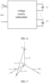
- Each voltage source submodule has a single-phase voltage source converter structure, with g (g is a positive integer and satisfies g ⁇ 2) output levels.
- a voltage between an AC positive pole and an AC negative pole of the voltage source submodule is denoted as u SM
- a current flowing through the voltage source submodule is denoted as i SM
- a direction from the positive terminal to the negative terminal of the voltage source submodule is as a positive direction, as illustrated in FIG. 6 .
- the voltage source submodule includes f (f is a positive integer and satisfies g > f ⁇ 1) DC capacitors.
- HBSM half-bridge submodule
- the A 1 -A 4 type submodules are well-known standard circuits, of which A 2 , A 3 , A 4 may refer to Reference ( Nami, A., et al., Modular Multilevel Converters for HVDC Applications: Review on Converter Cells and Functionalities. IEEE Transactions on Power Electronics, 2015. 30(1): p. 18-36 .).
- the power electronic switch of the voltage source submodule generally adopts a reverse conducting type IGBT or IGCT (which may be used independently or combined).
- an effective value of rated voltage of the overhead contact system T is denoted as U o
- an effective value of rated line voltage of the continuous co-phase traction substation connected to the synchronous public AC grid is denoted as U L
- a rated apparent capacity of a traction load of each continuous co-phase traction substation is denoted as S
- a power factor angle of a traction load of each traction substation is denoted as ⁇ x
- the continuous co-phase traction substation injects ports of the synchronous public AC power grid with a positive sequence current
- a power factor angle of a near-end port is denoted as ⁇
- the power factor angle is as positive with a voltage lagging behind a current.
- Line voltages of the secondary ports of the traction transformers T 1 and T 2 are denoted as u ab , u bc , u ca , respectively.
- a virtual neutral point of phase voltages of the secondary ports of the traction transformers T 1 and T 2 is denoted as o, and the corresponding phase voltages are denoted as u ao , u bo , u co , respectively.
- a form of phasor is expressed as U ⁇ oa , U ⁇ ob , U ⁇ oc , and a voltage phasor U ⁇ oa is as a reference phase.
- a diagram of a voltage phasor is illustrated in FIG.
- U m is an effective value of an AC component of a voltage of the bridge arm with upper and lower in each of the phases A 1 , B 1 , C 1 of the 4P-MMC 1
- U xo is an effective value of an AC component of a voltage of the bridge arm with upper and lower in the phase X 1 of the 4P-MMC 1
- ⁇ xo is a phase angle of an AC component of a voltage of the bridge arm with upper and lower in the phase X 1 of the 4P-MMC 1
- U x is an effective value of a voltage u xa of the output port Xc of the static power converter SPC
- ⁇ x is a phase angle of the voltage u xa ( t ).
- FIG. 8 Related electrical quantities and a reference direction of one set of SPC are illustrated in FIG. 8 .
- the input port Ac of the SPC in FIG. 2 connected to the concentrated grounding terminal as an example, the input port Ac and the secondary ports a 1 and a 2 of the traction transformer are both a reference level, then relative to the reference level (see point a in FIG.
- m, m x may be selected from [0.8,0.95] (m, m x ⁇ [0.8,0.95]).
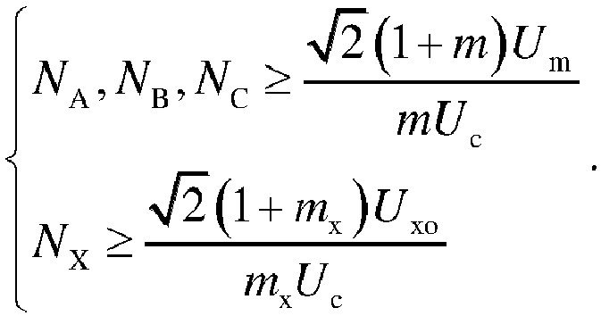
- the number N A , N B , N C , N X of the voltage source submodules on the upper and lower arms of the phases A 1 , B 1 , C 1 , X 1 of the 4P-MMC 1 may satisfy the following equation: N A , N B , N C ⁇ 2 1 + m U m mU c N X ⁇ 2 1 + m x U xo m x U c
- currents of the ports Ac, Bc, Cc, Xc of the SPC namely, currents of the AC ports of the phases A 1 , B 1 , C 1 , X 1 of the 4P-MMC 1 , are respectively denoted as i a ( t ), i b ( t ), i c ( t ), i x ( t ).
- Currents i Ta ( t ), i Tb ( t ), i Tc ( t ) of the secondary ports of the first traction transformer T 1 or the second traction transformer T 2 both are a positive sequence symmetrical current, with an effective value of I l .
- S is a rated apparent capacity of the traction load of the continuous co-phase traction substation.
- M continuous co-phase traction substations may share the traction load of the whole lines of the continuous traction overhead contact system.
- the traction transformers T 1 and T 2 may be used as standby for each other. Under this mode, when the continuous co-phase traction substation operates normally, in response to the first traction transformer T 1 being put into operation and the second traction transformer T 2 being in standby, the three-phase circuit breakers CB1 and CB6 are turned on, and the CB2 and CB7 are turned off. In response to a fault occurring when the first traction transformer T 1 , or the primary ports or the secondary ports of the first traction transformer T 1 are connected to lines for operation, the CB1 and CB6 are turned off in sequence to remove the first traction transformer T 1 from operation, then the CB2 and CB7 are turned on in sequence, and the second traction transformer T 2 is put into operation.
- the CB2 and CB7 are turned off in sequence, to remove the second traction transformer T 2 from operation, the CB1 and CB6 are turned on in sequence, and the first traction transformer T 1 is put into operation.
- the traction transformers T 1 and T 2 may operate in parallel. Under this mode, when the continuous co-phase traction substation operates normally, the first traction transformer T 1 and the second traction transformer T 2 both are put into operation, and the three-phase circuit breakers CB1, CB2, CB6, and CB7 are turned on. In response to the fault occurring when the first traction transformer T 1 , or the primary ports or the secondary ports of the first traction transformer T 1 are connected to the lines, the CB1 and CB6 are turned off to remove the first traction transformer T 1 from operation.
- k 4P-MMCs in one set of SPC of the continuous co-phase traction substation share the power of the traction load averagely, and a rated power capacity of the traction load allowable for each 4P-MMC is S / k.
- the traction substation When it is detected that the ith converter 4P-MMC i in the SPC has a fault, a trigger pulse for the power elements in the 4P-MMC i is immediately blocked, and the three-phase circuit breaker TB i and the single-phase circuit breaker SB i are turned off, and the remaining k-1 4P-MMCs in the SPC share the power of the traction load averagely. Accordingly, the rated power capacity of the traction load allowable for the traction substation is reduced to (k-1)S / k. When at most k-1 4P-MMCs in one set of SPC of the continuous co-phase traction substation have a fault, the traction substation is still operating in the continuous co-phase traction power supply system.
- an embodiment of the present disclosure provides the continuous co-phase traction substation that still has the capability of power supplying after the SPC is out of operation.
- the three-phase circuit breaker TB i and the single-phase circuit breaker SB i of each 4P-MMC for each SPC are turned off, and then the circuit breaker CB8 is turned on, thus the secondary ports b 1 (b 2 ) or the secondary ports c 1 (c 2 ) of the three-phase traction transformer T 1 or T 2 may directly supply power to the traction bus T-bus, to save the power capacity of other continuous co-phase traction substations, meanwhile, the output voltage of the SPCs the remaining M-1 continuous co-phase traction substations in the continuous co-phase traction power supply system may be adjusted to track the voltage of the ports b 1 (b 2 ) or c 1 (c 2 ) of the traction substation.
- the continuous co-phase traction power supply system for a form of direct power supplying as an example to explain a specific implementation of the present disclosure.
- the diagram of the system is illustrated in FIG. 3 .
- the traction transformers T 1 and T 2 both adopt YNd type wiring
- the static power converter SPC is configured with the output single-phase transformer T o
- the effective value I l of the current of the secondary port of the traction transformer and the effective value I x of the current of the output port of the SPC are respectively:
- parameter value Effective value of rated line voltage of synchronous public AC grid U L /kV 110 Frequency of synchronous public AC grid f/Hz 50 Effective value of rated line voltage of secondary side of traction transformer U l /kV 27.5 Effective value of rated voltage of output port of SPC U x /kV 31.8 Effective value of rated voltage of overhead contact system U o /kV 27.5 Transformation ratio of traction transformer K T 0.25 Transformation ratio of output transformer K o 0.87 rated DC voltage of 4P-MMC U d /kV 50 Rated apparent capacity of substation load S/MVA 40 Effective value of rated current of secondary side of traction transformer I l / A 840 Effective value of rated current of output port of SPC I x /A 1258 Number of half- bridge submodules in each bridge arm N A , N B , N C , N X 50 Rated DC voltage of half-bridge submodule U c /V 1000 Power
- a maximum withstand voltage, an effective current value, a current peak value and a capacity of each bridge arm of the 4P-MMC are shown in the following table.
- parameter A 1 B 1 C 1 X 1 Maximum withstand voltage of bridge arm /kV 47.4 47.4 47.4 47.4 Effective current value of bridge arm /A 249 498 498 747 Current peak value of bridge arm /A 431 861 861 1292 Capacity of bridge arm (effective value) /MVA 11.8 23.6 23.6 35.4 Capacity of bridge arm (peak value) /MVA 20.4 40.8 40.8 61.2
- a sum of capacities (effective value) of respective bridge arms of the 4P-MMC is 188.8MVA, and a sum of capacities (peak value) of respective bridge arms is 326.4MVA.
- a sum of capacities (effective value) of respective bridge arms is 289.2MVA, and a sum of capacities (peak value) of respective bridge arms is 498.4MVA.
- the 4P-MMC proposed in the present disclosure may reduce costs of power elements and capacitors by 35%.
Landscapes
- Engineering & Computer Science (AREA)
- Power Engineering (AREA)
- Mechanical Engineering (AREA)
- Ac-Ac Conversion (AREA)
- Rectifiers (AREA)
- Inverter Devices (AREA)
Claims (8)
- Système d'alimentation en énergie de traction cophasé continu basé sur un convertisseur multiniveau modulaire à quatre ports, comprenant une pluralité de sous-stations de traction cophasées continues agencées à intervalles, dans lequel un côté source de chaque sous-station de traction cophasée continue est connectable à un même réseau électrique public synchrone à courant alternatif, et un bus de traction au niveau d'un côté charge de chaque sous-station de traction cophasée continue est connectable à un système à ligne de contact aérienne T, toutes les sous-stations de traction cophasées continues sont connectables les unes aux autres par l'intermédiaire du système à ligne de contact aérienne T ;chaque sous-station de traction cophasée continue comprend un premier transformateur de traction T1, un second transformateur de traction T2, une pluralité de commutateurs et un convertisseur de puissance statique, SPC, avec trois ports d'entrée, Ac, Bc, Cc et un port de sortie, Xc ; le premier transformateur de traction T1 et le second transformateur de traction T2 présentent chacun une structure de transformateur triphasée ; les ports primaires des phases respectives du premier transformateur de traction T1 et du second transformateur de traction T2 sont respectivement connectables à trois phases A, B et C du réseau électrique public synchrone à courant alternatif par l'intermédiaire de disjoncteurs triphasés, CB1, CB2, dans lequel la phase A est en avance sur la phase B de 120 degrés et la phase A est en retard sur la phase C de 120 degrés, les ports secondaires des phases respectives du premier transformateur de traction T1 et du second transformateur de traction T2 sont respectivement connectés à trois ports d'entrée Ac, Bc et Cc du convertisseur de puissance statique, SPC par l'intermédiaire des disjoncteurs triphasés CB6 et CB7, un port de sortie Xc du convertisseur de puissance statique est connecté à un bus de traction, T-bus, le bus de traction T-bus est connectable au système à ligne de contact aérienne T par l'intermédiaire d'un disjoncteur monophasé CB3, et un rail est connecté à une borne de terre concentrée de la sous-station de traction cophasée continue correspondante par l'intermédiaire d'une ligne de retour ; la borne de terre concentrée de la sous-station de traction cophasée continue est connectée à un port d'entrée du convertisseur de puissance statique SPC, et le port d'entrée du convertisseur de puissance statique SPC connecté à la borne de terre concentrée dans chaque sous-station de traction cophasée continue présente un même numéro de séquence de phase ; le convertisseur de puissance statique SPC comprend k convertisseurs modulaires multiniveaux à quatre ports, 4P-MMC, en parallèle, chaque convertisseur modulaire multiniveau à quatre ports, 4P-MMC, comprend quatre phases A, B, C et X comprenant chacune un bras de pont supérieur et un bras de pont inférieur en série, les bornes positives des bras de pont supérieurs des quatre phases sont connectées en parallèle les unes avec les autres pour former un pôle positif à courant continu, CC+, et des pôles négatifs des bras de pont inférieurs des quatre phases sont connectés en parallèle les uns avec les autres pour former un pôle négatif à courant continu, CC-, les bornes négatives des bras de pont supérieurs des quatre phases et les bornes positives des bras de pont inférieurs des quatre phases sont respectivement connectées en série comme points médians des phases respectives ; les points médians des trois phases A, B et C de chaque convertisseur modulaire multiniveau à quatre ports, 4P-MMC sont respectivement connectés aux ports d'entrée correspondants Ac, Bc et Cc du convertisseur de puissance statique, SPC par l'intermédiaire d'un disjoncteur triphasé, TB, et le point médian de la phase X de chaque convertisseur modulaire multiniveau à quatre ports, 4P-MMC est respectivement connecté au port de sortie Xc du convertisseur de puissance statique SPC par l'intermédiaire d'un disjoncteur monophasé SB ;dans lequel les ports primaires du premier transformateur de traction T1 et du second transformateur de traction T2 présentent une même valeur effective U L de tension de ligne nominale, et des angles de phase des tensions de ligne avec une différence de 120 degrés dans l'ordre ; les ports secondaires du premier transformateur de traction T1 et du second transformateur de traction T2 présentent une même valeur effective Ul de tension de ligne nominale, et des angles de phase des tensions de ligne avec une différence de 120 degrés dans l'ordre ; un rapport de transformation de chacun du premier transformateur de traction T1 et du second transformateur de traction T2 est K T, c'est-à-dire :

- Système selon la revendication 1, dans lequel chaque sous-station de traction cophasée continue comprend en outre un transformateur de sortie monophasé To, un port P1 d'un enroulement primaire du transformateur de sortie monophasé To est connecté au port de sortie Xc du convertisseur de puissance statique SPC dans la sous-station de traction cophasée continue correspondante, tout port d'entrée du convertisseur de puissance statique SPC est connecté à l'autre port P0 de l'enroulement primaire du transformateur de sortie monophasé To par l'intermédiaire d'un disjoncteur CB4, et le port d'entrée du convertisseur de puissance statique SPC connecté au port P0 de l'enroulement primaire du transformateur de sortie monophasé To dans chaque sous-station de traction triphasée continue présente un même numéro de séquence de phase ; un port S1 d'un enroulement secondaire du transformateur de sortie monophasé To est connecté au bus de traction, T-bus, par l'intermédiaire d'un disjoncteur monophasé CB5, et l'autre port S0 de l'enroulement secondaire du transformateur de sortie monophasé To est connecté à la borne de terre concentrée dans la sous-station de traction cophasée continue correspondante ;
dans lequel une tension nominale côté secondaire du transformateur de sortie monophasé To et une tension nominale du bus de traction, T-bus, sont les mêmes, dont une valeur effective est désignée par U o, une tension nominale côté primaire du transformateur de sortie monophasé To et une tension de port du port de sortie, Xc, du convertisseur de puissance statique, SPC, correspondant sont les mêmes, et dont une valeur effective est désignée par U x, un rapport de transformation K o du transformateur de sortie monophasé To est :
- Système selon la revendication 1 ou 2, dans lequel dans chaque phase du convertisseur modulaire multiniveau à quatre ports, 4P-MMC, le bras de pont supérieur et le bras de pont inférieur présentent une même structure, comprenant une pluralité de sous-modules de source de tension et un inducteur de filtrage en série ; dans le bras de pont supérieur, une borne positive d'un premier des sous-modules de source de tension et une borne de l'inducteur de filtrage sont considérées respectivement comme une borne positive et une borne négative du bras de pont supérieur ; dans le bras de pont inférieur, une borne de l'inducteur de filtrage et une borne négative d'un dernier sous-module de source de tension sont considérées respectivement comme une borne positive et une borne négative du bras de pont inférieur.
- Système selon la revendication 3, dans lequel une valeur effective de tension nominale du système à ligne de contact aérienne T est désignée par U o, une valeur effective de tension de ligne nominale de la sous-station de traction cophasée continue connectable au réseau électrique public synchrone à courant alternatif est désignée par U L, et une capacité apparente nominale et un angle de facteur de puissance d'une charge de traction de chaque sous-station de traction cophasée continue sont respectivement désignés par S et φx ; la sous-station de traction cophasée continue injecte dans les ports du réseau électrique public synchrone à courant alternatif un courant de séquence positif, et un angle de facteur de puissance d'un port d'extrémité proche est désigné par φ, l'angle de facteur de puissance étant positif avec une tension en retard par rapport à un courant ; la borne de terre concentrée est connectée à un port d'entrée Ac du convertisseur de puissance statique, SPC, à savoir, le port d'entrée Ac et le port secondaire de chaque transformateur de traction connecté au port d'entrée Ac sont tous deux comme un niveau de référence, une caractéristique de quantité électrique principale du convertisseur de puissance statique, SPC, est définie comme suit :
des tensions des ports d'entrée Ac, Bc, Cc et les ports de sortie Xc du convertisseur de puissance statique, SPC, à savoir des tensions u aa(t), u ba(t), n ca (t) et u xa(t) des ports à courant alternatif des phases A, B, C et X de chaque convertisseur modulaire multiniveau à quatre ports, 4P-MMC sont respectivement exprimées comme suit : où, ω est une fréquence angulaire du réseau électrique public synchrone à courant alternatif, t est un temps de fonctionnement du système, Ul est la valeur effective de la tension de ligne nominale entre les ports secondaires du premier transformateur de traction T1 et du second transformateur de traction T2, et U x est une valeur effective de la tension u xa du port de sortie Xc du convertisseur statique de puissance SPC, δ x est un angle de phase de la tension u xa(t), pris comme positif en avant d'un phaseur de tension de référence U oa ;une valeur effective U m d'une composante à courant alternatif d'une tension du bras de pont supérieur et inférieur dans chacune des phases A, B et C de chaque convertisseur modulaire multiniveau à quatre ports, 4P-MMC est :
 une tension continue nominale U d entre le pôle positif à courant continu, CC+, et le pôle négatif à courant continu, DC-, de chaque convertisseur modulaire multiniveau à quatre ports, 4P-MMC est :
 où m est le degré de modulation des trois phases A, B et C de chaque convertisseur modulaire multiniveau à quatre ports, 4P-MMC ;une valeur effectiveU xo et un angle de phase δ xo d'une composante à courant alternatif d'une tension du bras de pont supérieur et inférieur dans la phase X de chaque convertisseur modulaire multiniveau à quatre ports, 4P-MMC sont respectivement :
 un degré de modulationm x de la phase X de chaque convertisseur modulaire multiniveau à quatre ports, 4P-MMC est :
 des tensions des bras supérieur et inférieur des phases A, B, C et X de chaque convertisseur modulaire multiniveau à quatre ports, 4P-MMC, sont respectivement :
 un courant du port secondaire de chacune des phases A, B et C du premier transformateur de traction T1 ou du second transformateur de traction T2 est un courant symétrique de séquence positive, avec une valeur effective de Il , une valeur effective d'un courant du port secondaire de la phase X du premier transformateur de traction T1 ou du second transformateur de traction T2 est Ix , qui satisfont respectivement :
 des courants ia (t), ib (t), ic (t), i x(t) des ports CA des phases A, B, C et X de chaque convertisseur modulaire multiniveau à quatre ports 4P-MMC sont respectivement :
 des courants des bras de pont supérieur et inférieur dans les phases A, B, C et X de chaque convertisseur modulaire multiniveau à quatre ports, 4P-MMC, sont respectivement :
 où, I da, I db, I dc, I dx sont des composantes à courant direct des courants des bras de pont des phases A1, B1, C1, X1, respectivement, qui satisfont :
- Système selon la revendication 4, dans lequel une plage de valeurs de l'angle de phase δ x de la tension u xa(t) est :

- Système selon la revendication 4, dans lequel chaque sous-module de source de tension présente une structure de convertisseur de source de tension monophasé, et des nombres N A, N B, Nc, N X des sous-modules de source de tension dans les bras de pont supérieur et inférieur dans les phases A, B, C, et X de chaque convertisseur modulaire multiniveau à quatre ports, 4P-MMC, satisfont respectivement :
- Système selon la revendication 4, k des convertisseurs modulaires multiniveaux à quatre ports, 4P-MMC dans le convertisseur de puissance statique, SPC, présentent une même spécification, et les courants des bras de pont supérieur et inférieur dans les phases respectives de chaque convertisseur modulaire multiniveau à quatre ports, 4P-MMC, sont respectivement exprimés comme suit :

- Système selon la revendication 7, dans lequel chaque phase de chaque convertisseur modulaire multiniveau à quatre ports, 4P-MMC, dans le convertisseur de puissance statique, SPC présente un même degré de modulation, qui est m=mx.
Applications Claiming Priority (3)
| Application Number | Priority Date | Filing Date | Title |
|---|---|---|---|
| CN201911391690 | 2019-12-30 | ||
| CN202010261430.4A CN111446867B (zh) | 2019-12-30 | 2020-04-03 | 基于四端口模块化多电平变流器的贯通同相牵引供电系统 |
| PCT/CN2020/102122 WO2021196448A1 (fr) | 2019-12-30 | 2020-07-15 | Système d'alimentation en énergie de traction co-phasé interconnecté fondé sur un convertisseur multiniveau modulaire à quatre ports |
Publications (3)
| Publication Number | Publication Date |
|---|---|
| EP4131762A1 EP4131762A1 (fr) | 2023-02-08 |
| EP4131762A4 EP4131762A4 (fr) | 2024-05-01 |
| EP4131762B1 true EP4131762B1 (fr) | 2025-06-04 |
Family
ID=71649931
Family Applications (1)
| Application Number | Title | Priority Date | Filing Date |
|---|---|---|---|
| EP20928166.6A Active EP4131762B1 (fr) | 2019-12-30 | 2020-07-15 | Système d'alimentation en énergie de traction co-phasé interconnecté fondé sur un convertisseur multiniveau modulaire à quatre ports |
Country Status (3)
| Country | Link |
|---|---|
| EP (1) | EP4131762B1 (fr) |
| CN (1) | CN111446867B (fr) |
| WO (1) | WO2021196448A1 (fr) |
Families Citing this family (24)
| Publication number | Priority date | Publication date | Assignee | Title |
|---|---|---|---|---|
| CN111890998A (zh) * | 2020-08-28 | 2020-11-06 | 成都尚华电气有限公司 | 同相供电装置、贯通式同相供电构造、系统及控制方法 |
| CN112886827B (zh) * | 2021-02-01 | 2022-06-03 | 中科兆和电力技术(山东)有限公司 | 半容量同相供电变流器 |
| CN112977181A (zh) * | 2021-03-18 | 2021-06-18 | 清华大学 | 实现贯通同相的柔性交流牵引供电系统及其运行方法 |
| CN112865098B (zh) * | 2021-03-18 | 2022-10-21 | 中铁电气化局集团有限公司 | 和异相供电兼容的全贯通式柔性牵引供电系统 |
| CN113002333B (zh) * | 2021-03-24 | 2022-07-19 | 清华大学 | 全贯通式柔性交流牵引供电系统的大功率变流器接地方法 |
| CN113076660B (zh) * | 2021-04-28 | 2023-01-31 | 中铁二院工程集团有限责任公司 | 一种混合电源系统双边供电方式电气化铁路环流计算方法 |
| CN113224762B (zh) * | 2021-05-28 | 2022-05-10 | 西南交通大学 | 一种长距离贯通柔性牵引供电系统及其优化控制方法 |
| CN113659447B (zh) * | 2021-07-20 | 2023-07-28 | 许继集团有限公司 | 一种同相供电装置串联侧电压采样极性自动校正方法 |
| CN113978321B (zh) * | 2021-10-26 | 2024-05-31 | 中铁第一勘察设计院集团有限公司 | 双边贯通供电分段所和牵引供电系统 |
| CN114421457B (zh) * | 2021-12-21 | 2022-12-06 | 西南交通大学 | 一种基于高降压比变压器的贯通柔性牵引变电所 |
| CN114498576B (zh) * | 2021-12-21 | 2022-10-14 | 西南交通大学 | 一种基于mmc的贯通柔性牵引变电所及其保护配置方法 |
| CN114379367B (zh) * | 2021-12-30 | 2024-06-14 | 中车永济电机有限公司 | 机车牵引电传动系统及其控制方法 |
| CN114475370B (zh) * | 2022-03-14 | 2023-04-07 | 西南交通大学 | 一种电缆贯通供电系统接触网短路分段保护方法 |
| CN114825587B (zh) * | 2022-04-07 | 2023-04-25 | 西南交通大学 | 一种双边牵引供电单树形外部电源备投构造及控制方法 |
| CN114604141B (zh) * | 2022-04-07 | 2023-04-25 | 西南交通大学 | 一种双边贯通同相供电系统及控制方法 |
| CN114825276B (zh) * | 2022-04-08 | 2024-08-27 | 清华大学 | 贯通同相牵引供电系统的变流器保护系统及方法 |
| CN114977484B (zh) * | 2022-04-20 | 2025-09-30 | 中铁电气化局集团有限公司 | 贯通同相牵引供电变流站级控制系统 |
| CN114771360B (zh) * | 2022-04-21 | 2023-04-07 | 西南交通大学 | 一种电气化铁路交直流牵引供电构造及控制方法 |
| CN115189354B (zh) * | 2022-08-05 | 2026-04-10 | 西南交通大学 | 一种电气化铁路贯通式同相供电系统构造 |
| CN115589018A (zh) * | 2022-08-30 | 2023-01-10 | 中建一局集团建设发展有限公司 | 适于大功率的牵引供电系统mmc型光伏并网装置及控制方法 |
| CN115622068B (zh) * | 2022-12-16 | 2024-04-05 | 普世通(北京)电气有限公司 | 一种配电网供电电压偏差及中断治理装置及其控制方法 |
| CN116683548B (zh) * | 2023-05-30 | 2024-02-06 | 西南交通大学 | 基于mmc的柔性直流牵引供电综合协调控制方法 |
| CN116890709B (zh) * | 2023-05-30 | 2024-03-12 | 西南交通大学 | 一种柔性牵引变电所过渡改造结构的控制方法 |
| CN117856255B (zh) * | 2024-03-06 | 2024-05-14 | 中铁电气工业有限公司 | 全贯通式柔性交流牵引供电多重化冗余站级系统 |
Family Cites Families (9)
| Publication number | Priority date | Publication date | Assignee | Title |
|---|---|---|---|---|
| CN103552487B (zh) * | 2013-10-17 | 2015-11-18 | 南车株洲电力机车研究所有限公司 | 一种同相供电装置及牵引供电系统 |
| CN103972920A (zh) * | 2014-05-14 | 2014-08-06 | 国网上海市电力公司 | 紧凑型模块化多电平三极直流输电系统 |
| JP5730458B1 (ja) * | 2014-10-08 | 2015-06-10 | 三菱電機株式会社 | 電力変換装置 |
| JP6370702B2 (ja) * | 2014-12-24 | 2018-08-08 | 株式会社東芝 | 電力変換装置 |
| CN105470958B (zh) * | 2015-12-31 | 2019-03-12 | 北京交通大学 | 一种模块化多电平结构的交直交牵引供电系统 |
| CN108400715A (zh) * | 2018-02-07 | 2018-08-14 | 西南交通大学 | 采用模块化多电平变流器的铁路牵引供电及列车传动系统 |
| CN109050352B (zh) * | 2018-07-10 | 2020-06-26 | 中国科学院电工研究所 | 贯通式同相牵引供电系统、牵引变电所及其供电控制方法 |
| CN109728592A (zh) * | 2019-02-28 | 2019-05-07 | 西南交通大学 | 一种电气化铁路牵引供电系统 |
| CN110341728B (zh) * | 2019-08-19 | 2024-01-26 | 西南交通大学 | 一种电气化铁路贯通式牵引供电系统 |
-
2020
- 2020-04-03 CN CN202010261430.4A patent/CN111446867B/zh not_active Expired - Fee Related
- 2020-07-15 WO PCT/CN2020/102122 patent/WO2021196448A1/fr not_active Ceased
- 2020-07-15 EP EP20928166.6A patent/EP4131762B1/fr active Active
Also Published As
| Publication number | Publication date |
|---|---|
| CN111446867B (zh) | 2021-05-28 |
| EP4131762A1 (fr) | 2023-02-08 |
| WO2021196448A1 (fr) | 2021-10-07 |
| EP4131762A4 (fr) | 2024-05-01 |
| CN111446867A (zh) | 2020-07-24 |
Similar Documents
| Publication | Publication Date | Title |
|---|---|---|
| EP4131762B1 (fr) | Système d'alimentation en énergie de traction co-phasé interconnecté fondé sur un convertisseur multiniveau modulaire à quatre ports | |
| CN111446866B (zh) | 基于平衡变压器和四端口mmc的贯通同相牵引供电系统 | |
| US20220166343A1 (en) | Solid-state transformer having uninterrupted operation ability under ac/dc fault and control method thereof | |
| CN105490552B (zh) | 一种基于mmc的固态变压器以及控制方法 | |
| CN103928928B (zh) | 一种高速铁路电能质量及牵引网电压综合补偿系统 | |
| US20230356629A1 (en) | System for implementing continuous co-phase flexible alternating current traction power supply and operation mode therefor | |
| CN104410095B (zh) | 基于多端直流输电的交流电气化铁道同相贯通供电系统 | |
| CN105470958B (zh) | 一种模块化多电平结构的交直交牵引供电系统 | |
| CN106532734A (zh) | 适于高速电气化铁路的同相牵引供电系统 | |
| CN102624070A (zh) | 一种基于九相自耦移相变压器的对称式ups电源系统 | |
| CN101856979A (zh) | 一种电气化铁路同相供电装置 | |
| CN105514957A (zh) | 一种混合背靠背直流输电系统及潮流反转控制方法 | |
| CN102280880B (zh) | 一种差异化补偿的电气化铁路电能质量治理装置 | |
| Li et al. | Four-port modular multilevel AC/AC converter in continuous co-phase traction power supply application | |
| CN102291016A (zh) | 一种电气化铁路电能质量调节器 | |
| CN110729717B (zh) | 一种双全桥背靠背变流器并联型牵引补偿系统 | |
| Habibolahzadeh et al. | Improved railway static power conditioner using c-type filter in Scott co-phase traction power supply system | |
| CN202183601U (zh) | 一种差异化补偿的电气化铁路电能质量治理装置 | |
| Ismail et al. | A review of recent HVDC tapping topologies | |
| CN116995646B (zh) | 一种柔性牵引变电所的故障自愈控制方法 | |
| CN115276032B (zh) | 基于平衡变压器和mmc的贯通式柔性牵引供电装置 | |
| Roudsari et al. | A Z-source railway static power conditioner for power quality improvement | |
| CN116488539A (zh) | 一种高功率密度模块和模块化中压变频器 | |
| CN114389255A (zh) | 一种牵引变电所主电路 | |
| CN114421457B (zh) | 一种基于高降压比变压器的贯通柔性牵引变电所 |
Legal Events
| Date | Code | Title | Description |
|---|---|---|---|
| STAA | Information on the status of an ep patent application or granted ep patent |
Free format text: STATUS: THE INTERNATIONAL PUBLICATION HAS BEEN MADE |
|
| PUAI | Public reference made under article 153(3) epc to a published international application that has entered the european phase |
Free format text: ORIGINAL CODE: 0009012 |
|
| STAA | Information on the status of an ep patent application or granted ep patent |
Free format text: STATUS: REQUEST FOR EXAMINATION WAS MADE |
|
| 17P | Request for examination filed |
Effective date: 20221102 |
|
| AK | Designated contracting states |
Kind code of ref document: A1 Designated state(s): AL AT BE BG CH CY CZ DE DK EE ES FI FR GB GR HR HU IE IS IT LI LT LU LV MC MK MT NL NO PL PT RO RS SE SI SK SM TR |
|
| DAV | Request for validation of the european patent (deleted) | ||
| DAX | Request for extension of the european patent (deleted) | ||
| REG | Reference to a national code |
Ref country code: DE Ref legal event code: R079 Free format text: PREVIOUS MAIN CLASS: H02M0005420000 Ipc: H02M0005297000 Ref document number: 602020052483 Country of ref document: DE |
|
| A4 | Supplementary search report drawn up and despatched |
Effective date: 20240405 |
|
| RIC1 | Information provided on ipc code assigned before grant |
Ipc: B60M 3/00 20060101ALI20240328BHEP Ipc: H02M 5/42 20060101ALI20240328BHEP Ipc: H02M 7/483 20070101ALI20240328BHEP Ipc: H02M 5/297 20060101AFI20240328BHEP |
|
| GRAP | Despatch of communication of intention to grant a patent |
Free format text: ORIGINAL CODE: EPIDOSNIGR1 |
|
| STAA | Information on the status of an ep patent application or granted ep patent |
Free format text: STATUS: GRANT OF PATENT IS INTENDED |
|
| INTG | Intention to grant announced |
Effective date: 20250115 |
|
| GRAS | Grant fee paid |
Free format text: ORIGINAL CODE: EPIDOSNIGR3 |
|
| GRAA | (expected) grant |
Free format text: ORIGINAL CODE: 0009210 |
|
| STAA | Information on the status of an ep patent application or granted ep patent |
Free format text: STATUS: THE PATENT HAS BEEN GRANTED |
|
| AK | Designated contracting states |
Kind code of ref document: B1 Designated state(s): AL AT BE BG CH CY CZ DE DK EE ES FI FR GB GR HR HU IE IS IT LI LT LU LV MC MK MT NL NO PL PT RO RS SE SI SK SM TR |
|
| REG | Reference to a national code |
Ref country code: GB Ref legal event code: FG4D |
|
| REG | Reference to a national code |
Ref country code: CH Ref legal event code: EP |
|
| REG | Reference to a national code |
Ref country code: DE Ref legal event code: R096 Ref document number: 602020052483 Country of ref document: DE |
|
| REG | Reference to a national code |
Ref country code: IE Ref legal event code: FG4D |
|
| REG | Reference to a national code |
Ref country code: NL Ref legal event code: MP Effective date: 20250604 |
|
| PG25 | Lapsed in a contracting state [announced via postgrant information from national office to epo] |
Ref country code: FI Free format text: LAPSE BECAUSE OF FAILURE TO SUBMIT A TRANSLATION OF THE DESCRIPTION OR TO PAY THE FEE WITHIN THE PRESCRIBED TIME-LIMIT Effective date: 20250604 Ref country code: ES Free format text: LAPSE BECAUSE OF FAILURE TO SUBMIT A TRANSLATION OF THE DESCRIPTION OR TO PAY THE FEE WITHIN THE PRESCRIBED TIME-LIMIT Effective date: 20250604 |
|
| PGFP | Annual fee paid to national office [announced via postgrant information from national office to epo] |
Ref country code: DE Payment date: 20250805 Year of fee payment: 6 |
|
| REG | Reference to a national code |
Ref country code: LT Ref legal event code: MG9D |
|
| PG25 | Lapsed in a contracting state [announced via postgrant information from national office to epo] |
Ref country code: NO Free format text: LAPSE BECAUSE OF FAILURE TO SUBMIT A TRANSLATION OF THE DESCRIPTION OR TO PAY THE FEE WITHIN THE PRESCRIBED TIME-LIMIT Effective date: 20250904 Ref country code: GR Free format text: LAPSE BECAUSE OF FAILURE TO SUBMIT A TRANSLATION OF THE DESCRIPTION OR TO PAY THE FEE WITHIN THE PRESCRIBED TIME-LIMIT Effective date: 20250905 |
|
| PG25 | Lapsed in a contracting state [announced via postgrant information from national office to epo] |
Ref country code: PL Free format text: LAPSE BECAUSE OF FAILURE TO SUBMIT A TRANSLATION OF THE DESCRIPTION OR TO PAY THE FEE WITHIN THE PRESCRIBED TIME-LIMIT Effective date: 20250604 |
|
| PG25 | Lapsed in a contracting state [announced via postgrant information from national office to epo] |
Ref country code: BG Free format text: LAPSE BECAUSE OF FAILURE TO SUBMIT A TRANSLATION OF THE DESCRIPTION OR TO PAY THE FEE WITHIN THE PRESCRIBED TIME-LIMIT Effective date: 20250604 |
|
| PGFP | Annual fee paid to national office [announced via postgrant information from national office to epo] |
Ref country code: GB Payment date: 20250731 Year of fee payment: 6 |
|
| PG25 | Lapsed in a contracting state [announced via postgrant information from national office to epo] |
Ref country code: HR Free format text: LAPSE BECAUSE OF FAILURE TO SUBMIT A TRANSLATION OF THE DESCRIPTION OR TO PAY THE FEE WITHIN THE PRESCRIBED TIME-LIMIT Effective date: 20250604 |
|
| PGFP | Annual fee paid to national office [announced via postgrant information from national office to epo] |
Ref country code: CH Payment date: 20250818 Year of fee payment: 6 |
|
| PG25 | Lapsed in a contracting state [announced via postgrant information from national office to epo] |
Ref country code: RS Free format text: LAPSE BECAUSE OF FAILURE TO SUBMIT A TRANSLATION OF THE DESCRIPTION OR TO PAY THE FEE WITHIN THE PRESCRIBED TIME-LIMIT Effective date: 20250904 |
|
| PG25 | Lapsed in a contracting state [announced via postgrant information from national office to epo] |
Ref country code: LV Free format text: LAPSE BECAUSE OF FAILURE TO SUBMIT A TRANSLATION OF THE DESCRIPTION OR TO PAY THE FEE WITHIN THE PRESCRIBED TIME-LIMIT Effective date: 20250604 |
|
| PG25 | Lapsed in a contracting state [announced via postgrant information from national office to epo] |
Ref country code: NL Free format text: LAPSE BECAUSE OF FAILURE TO SUBMIT A TRANSLATION OF THE DESCRIPTION OR TO PAY THE FEE WITHIN THE PRESCRIBED TIME-LIMIT Effective date: 20250604 |
|
| PG25 | Lapsed in a contracting state [announced via postgrant information from national office to epo] |
Ref country code: PT Free format text: LAPSE BECAUSE OF FAILURE TO SUBMIT A TRANSLATION OF THE DESCRIPTION OR TO PAY THE FEE WITHIN THE PRESCRIBED TIME-LIMIT Effective date: 20251006 |
|
| REG | Reference to a national code |
Ref country code: AT Ref legal event code: MK05 Ref document number: 1801359 Country of ref document: AT Kind code of ref document: T Effective date: 20250604 |
|
| PG25 | Lapsed in a contracting state [announced via postgrant information from national office to epo] |
Ref country code: IS Free format text: LAPSE BECAUSE OF FAILURE TO SUBMIT A TRANSLATION OF THE DESCRIPTION OR TO PAY THE FEE WITHIN THE PRESCRIBED TIME-LIMIT Effective date: 20251004 |
|
| PG25 | Lapsed in a contracting state [announced via postgrant information from national office to epo] |
Ref country code: SM Free format text: LAPSE BECAUSE OF FAILURE TO SUBMIT A TRANSLATION OF THE DESCRIPTION OR TO PAY THE FEE WITHIN THE PRESCRIBED TIME-LIMIT Effective date: 20250604 Ref country code: AT Free format text: LAPSE BECAUSE OF FAILURE TO SUBMIT A TRANSLATION OF THE DESCRIPTION OR TO PAY THE FEE WITHIN THE PRESCRIBED TIME-LIMIT Effective date: 20250604 |
|
| PG25 | Lapsed in a contracting state [announced via postgrant information from national office to epo] |
Ref country code: CZ Free format text: LAPSE BECAUSE OF FAILURE TO SUBMIT A TRANSLATION OF THE DESCRIPTION OR TO PAY THE FEE WITHIN THE PRESCRIBED TIME-LIMIT Effective date: 20250604 |
|
| PG25 | Lapsed in a contracting state [announced via postgrant information from national office to epo] |
Ref country code: EE Free format text: LAPSE BECAUSE OF FAILURE TO SUBMIT A TRANSLATION OF THE DESCRIPTION OR TO PAY THE FEE WITHIN THE PRESCRIBED TIME-LIMIT Effective date: 20250604 |
|
| PG25 | Lapsed in a contracting state [announced via postgrant information from national office to epo] |
Ref country code: SK Free format text: LAPSE BECAUSE OF FAILURE TO SUBMIT A TRANSLATION OF THE DESCRIPTION OR TO PAY THE FEE WITHIN THE PRESCRIBED TIME-LIMIT Effective date: 20250604 |
|
| PG25 | Lapsed in a contracting state [announced via postgrant information from national office to epo] |
Ref country code: IT Free format text: LAPSE BECAUSE OF FAILURE TO SUBMIT A TRANSLATION OF THE DESCRIPTION OR TO PAY THE FEE WITHIN THE PRESCRIBED TIME-LIMIT Effective date: 20250604 |
|
| PG25 | Lapsed in a contracting state [announced via postgrant information from national office to epo] |
Ref country code: RO Free format text: LAPSE BECAUSE OF FAILURE TO SUBMIT A TRANSLATION OF THE DESCRIPTION OR TO PAY THE FEE WITHIN THE PRESCRIBED TIME-LIMIT Effective date: 20250604 |
|
| REG | Reference to a national code |
Ref country code: DE Ref legal event code: R097 Ref document number: 602020052483 Country of ref document: DE |
|
| PG25 | Lapsed in a contracting state [announced via postgrant information from national office to epo] |
Ref country code: LU Free format text: LAPSE BECAUSE OF NON-PAYMENT OF DUE FEES Effective date: 20250715 |
|
| REG | Reference to a national code |
Ref country code: BE Ref legal event code: MM Effective date: 20250731 |
|
| PG25 | Lapsed in a contracting state [announced via postgrant information from national office to epo] |
Ref country code: MC Free format text: LAPSE BECAUSE OF FAILURE TO SUBMIT A TRANSLATION OF THE DESCRIPTION OR TO PAY THE FEE WITHIN THE PRESCRIBED TIME-LIMIT Effective date: 20250604 |
|
| PLBE | No opposition filed within time limit |
Free format text: ORIGINAL CODE: 0009261 |
|
| STAA | Information on the status of an ep patent application or granted ep patent |
Free format text: STATUS: NO OPPOSITION FILED WITHIN TIME LIMIT |
|
| PG25 | Lapsed in a contracting state [announced via postgrant information from national office to epo] |
Ref country code: DK Free format text: LAPSE BECAUSE OF FAILURE TO SUBMIT A TRANSLATION OF THE DESCRIPTION OR TO PAY THE FEE WITHIN THE PRESCRIBED TIME-LIMIT Effective date: 20250604 |
|
| PG25 | Lapsed in a contracting state [announced via postgrant information from national office to epo] |
Ref country code: BE Free format text: LAPSE BECAUSE OF NON-PAYMENT OF DUE FEES Effective date: 20250731 |
|
| REG | Reference to a national code |
Ref country code: CH Ref legal event code: L10 Free format text: ST27 STATUS EVENT CODE: U-0-0-L10-L00 (AS PROVIDED BY THE NATIONAL OFFICE) Effective date: 20260416 |