EP4131764B1 - Speicherbatteriesystem und verfahren zur unterdrückung von frequenzschwankungen eines wechselstromsystems - Google Patents
Speicherbatteriesystem und verfahren zur unterdrückung von frequenzschwankungen eines wechselstromsystems Download PDFInfo
- Publication number
- EP4131764B1 EP4131764B1 EP20928074.2A EP20928074A EP4131764B1 EP 4131764 B1 EP4131764 B1 EP 4131764B1 EP 20928074 A EP20928074 A EP 20928074A EP 4131764 B1 EP4131764 B1 EP 4131764B1
- Authority
- EP
- European Patent Office
- Prior art keywords
- storage battery
- frequency
- battery unit
- active power
- threshold value
- Prior art date
- Legal status (The legal status is an assumption and is not a legal conclusion. Google has not performed a legal analysis and makes no representation as to the accuracy of the status listed.)
- Active
Links
Images



Classifications
-
- H—ELECTRICITY
- H02—GENERATION; CONVERSION OR DISTRIBUTION OF ELECTRIC POWER
- H02J—ELECTRIC POWER NETWORKS; CIRCUIT ARRANGEMENTS OR SYSTEMS FOR SUPPLYING OR DISTRIBUTING ELECTRIC POWER; SYSTEMS FOR STORING ELECTRIC ENERGY
- H02J3/00—Circuit arrangements for AC mains or AC distribution networks
- H02J3/28—Arrangements for balancing of the load in networks by storage of energy
- H02J3/32—Arrangements for balancing of the load in networks by storage of energy using batteries or super capacitors with converting means
-
- G—PHYSICS
- G01—MEASURING; TESTING
- G01R—MEASURING ELECTRIC VARIABLES; MEASURING MAGNETIC VARIABLES
- G01R23/00—Arrangements for measuring frequencies; Arrangements for analysing frequency spectra
- G01R23/02—Arrangements for measuring frequency, e.g. pulse repetition rate; Arrangements for measuring period of current or voltage
- G01R23/15—Indicating that frequency of pulses is either above or below a predetermined value or within or outside a predetermined range of values, by making use of non-linear or digital elements (indicating that pulse width is above or below a certain limit)
-
- H—ELECTRICITY
- H01—ELECTRIC ELEMENTS
- H01M—PROCESSES OR MEANS, e.g. BATTERIES, FOR THE DIRECT CONVERSION OF CHEMICAL ENERGY INTO ELECTRICAL ENERGY
- H01M10/00—Secondary cells; Manufacture thereof
- H01M10/42—Methods or arrangements for servicing or maintenance of secondary cells or secondary half-cells
- H01M10/425—Structural combination with electronic components, e.g. electronic circuits integrated to the outside of the casing
-
- H—ELECTRICITY
- H02—GENERATION; CONVERSION OR DISTRIBUTION OF ELECTRIC POWER
- H02J—ELECTRIC POWER NETWORKS; CIRCUIT ARRANGEMENTS OR SYSTEMS FOR SUPPLYING OR DISTRIBUTING ELECTRIC POWER; SYSTEMS FOR STORING ELECTRIC ENERGY
- H02J3/00—Circuit arrangements for AC mains or AC distribution networks
- H02J3/001—Arrangements for handling faults or abnormalities, e.g. emergencies or contingencies
- H02J3/0014—Arrangements for handling faults or abnormalities, e.g. emergencies or contingencies for preventing or reducing power oscillations in networks
- H02J3/00142—Oscillations concerning frequency
-
- H—ELECTRICITY
- H02—GENERATION; CONVERSION OR DISTRIBUTION OF ELECTRIC POWER
- H02J—ELECTRIC POWER NETWORKS; CIRCUIT ARRANGEMENTS OR SYSTEMS FOR SUPPLYING OR DISTRIBUTING ELECTRIC POWER; SYSTEMS FOR STORING ELECTRIC ENERGY
- H02J3/00—Circuit arrangements for AC mains or AC distribution networks
- H02J3/38—Arrangements for feeding a single network from two or more generators or sources in parallel; Arrangements for feeding already energised networks from additional generators or sources in parallel
- H02J3/381—Dispersed generators
-
- H—ELECTRICITY
- H02—GENERATION; CONVERSION OR DISTRIBUTION OF ELECTRIC POWER
- H02J—ELECTRIC POWER NETWORKS; CIRCUIT ARRANGEMENTS OR SYSTEMS FOR SUPPLYING OR DISTRIBUTING ELECTRIC POWER; SYSTEMS FOR STORING ELECTRIC ENERGY
- H02J3/00—Circuit arrangements for AC mains or AC distribution networks
- H02J3/38—Arrangements for feeding a single network from two or more generators or sources in parallel; Arrangements for feeding already energised networks from additional generators or sources in parallel
- H02J3/46—Controlling the sharing of generated power between the generators, sources or networks
- H02J3/48—Controlling the sharing of active power
-
- H—ELECTRICITY
- H02—GENERATION; CONVERSION OR DISTRIBUTION OF ELECTRIC POWER
- H02J—ELECTRIC POWER NETWORKS; CIRCUIT ARRANGEMENTS OR SYSTEMS FOR SUPPLYING OR DISTRIBUTING ELECTRIC POWER; SYSTEMS FOR STORING ELECTRIC ENERGY
- H02J7/00—Circuit arrangements for charging or discharging batteries or for supplying loads from batteries
- H02J7/50—Circuit arrangements for charging or discharging batteries or for supplying loads from batteries acting upon multiple batteries simultaneously or sequentially
-
- H—ELECTRICITY
- H02—GENERATION; CONVERSION OR DISTRIBUTION OF ELECTRIC POWER
- H02J—ELECTRIC POWER NETWORKS; CIRCUIT ARRANGEMENTS OR SYSTEMS FOR SUPPLYING OR DISTRIBUTING ELECTRIC POWER; SYSTEMS FOR STORING ELECTRIC ENERGY
- H02J7/00—Circuit arrangements for charging or discharging batteries or for supplying loads from batteries
- H02J7/855—Circuit arrangements for charging or discharging batteries or for supplying loads from batteries with circuits adapted for supplying loads from the battery
-
- H—ELECTRICITY
- H02—GENERATION; CONVERSION OR DISTRIBUTION OF ELECTRIC POWER
- H02J—ELECTRIC POWER NETWORKS; CIRCUIT ARRANGEMENTS OR SYSTEMS FOR SUPPLYING OR DISTRIBUTING ELECTRIC POWER; SYSTEMS FOR STORING ELECTRIC ENERGY
- H02J7/00—Circuit arrangements for charging or discharging batteries or for supplying loads from batteries
- H02J7/90—Regulation of charging or discharging current or voltage
- H02J7/933—Regulation of charging or discharging current or voltage the cycle being controlled or terminated in response to electric parameters
-
- H—ELECTRICITY
- H02—GENERATION; CONVERSION OR DISTRIBUTION OF ELECTRIC POWER
- H02M—APPARATUS FOR CONVERSION BETWEEN AC AND AC, BETWEEN AC AND DC, OR BETWEEN DC AND DC, AND FOR USE WITH MAINS OR SIMILAR POWER SUPPLY SYSTEMS; CONVERSION OF DC OR AC INPUT POWER INTO SURGE OUTPUT POWER; CONTROL OR REGULATION THEREOF
- H02M1/00—Details of apparatus for conversion
- H02M1/32—Means for protecting converters other than automatic disconnection
- H02M1/325—Means for protecting converters other than automatic disconnection with means for allowing continuous operation despite a fault, i.e. fault tolerant converters
-
- H—ELECTRICITY
- H02—GENERATION; CONVERSION OR DISTRIBUTION OF ELECTRIC POWER
- H02M—APPARATUS FOR CONVERSION BETWEEN AC AND AC, BETWEEN AC AND DC, OR BETWEEN DC AND DC, AND FOR USE WITH MAINS OR SIMILAR POWER SUPPLY SYSTEMS; CONVERSION OF DC OR AC INPUT POWER INTO SURGE OUTPUT POWER; CONTROL OR REGULATION THEREOF
- H02M7/00—Conversion of AC power input into DC power output; Conversion of DC power input into AC power output
- H02M7/66—Conversion of AC power input into DC power output; Conversion of DC power input into AC power output with possibility of reversal
- H02M7/68—Conversion of AC power input into DC power output; Conversion of DC power input into AC power output with possibility of reversal by static converters
- H02M7/72—Conversion of AC power input into DC power output; Conversion of DC power input into AC power output with possibility of reversal by static converters using discharge tubes with control electrode or semiconductor devices with control electrode
- H02M7/79—Conversion of AC power input into DC power output; Conversion of DC power input into AC power output with possibility of reversal by static converters using discharge tubes with control electrode or semiconductor devices with control electrode using devices of a triode or transistor type requiring continuous application of a control signal
-
- H—ELECTRICITY
- H01—ELECTRIC ELEMENTS
- H01M—PROCESSES OR MEANS, e.g. BATTERIES, FOR THE DIRECT CONVERSION OF CHEMICAL ENERGY INTO ELECTRICAL ENERGY
- H01M10/00—Secondary cells; Manufacture thereof
- H01M10/42—Methods or arrangements for servicing or maintenance of secondary cells or secondary half-cells
- H01M10/425—Structural combination with electronic components, e.g. electronic circuits integrated to the outside of the casing
- H01M2010/4271—Battery management systems including electronic circuits, e.g. control of current or voltage to keep battery in healthy state, cell balancing
-
- H—ELECTRICITY
- H02—GENERATION; CONVERSION OR DISTRIBUTION OF ELECTRIC POWER
- H02J—ELECTRIC POWER NETWORKS; CIRCUIT ARRANGEMENTS OR SYSTEMS FOR SUPPLYING OR DISTRIBUTING ELECTRIC POWER; SYSTEMS FOR STORING ELECTRIC ENERGY
- H02J2207/00—Details of circuit arrangements for charging or discharging batteries or supplying loads from batteries
- H02J2207/20—Charging or discharging characterised by the power electronics converter
-
- Y—GENERAL TAGGING OF NEW TECHNOLOGICAL DEVELOPMENTS; GENERAL TAGGING OF CROSS-SECTIONAL TECHNOLOGIES SPANNING OVER SEVERAL SECTIONS OF THE IPC; TECHNICAL SUBJECTS COVERED BY FORMER USPC CROSS-REFERENCE ART COLLECTIONS [XRACs] AND DIGESTS
- Y02—TECHNOLOGIES OR APPLICATIONS FOR MITIGATION OR ADAPTATION AGAINST CLIMATE CHANGE
- Y02E—REDUCTION OF GREENHOUSE GAS [GHG] EMISSIONS, RELATED TO ENERGY GENERATION, TRANSMISSION OR DISTRIBUTION
- Y02E40/00—Technologies for an efficient electrical power generation, transmission or distribution
- Y02E40/70—Smart grids as climate change mitigation technology in the energy generation sector
-
- Y—GENERAL TAGGING OF NEW TECHNOLOGICAL DEVELOPMENTS; GENERAL TAGGING OF CROSS-SECTIONAL TECHNOLOGIES SPANNING OVER SEVERAL SECTIONS OF THE IPC; TECHNICAL SUBJECTS COVERED BY FORMER USPC CROSS-REFERENCE ART COLLECTIONS [XRACs] AND DIGESTS
- Y02—TECHNOLOGIES OR APPLICATIONS FOR MITIGATION OR ADAPTATION AGAINST CLIMATE CHANGE
- Y02E—REDUCTION OF GREENHOUSE GAS [GHG] EMISSIONS, RELATED TO ENERGY GENERATION, TRANSMISSION OR DISTRIBUTION
- Y02E60/00—Enabling technologies; Technologies with a potential or indirect contribution to GHG emissions mitigation
-
- Y—GENERAL TAGGING OF NEW TECHNOLOGICAL DEVELOPMENTS; GENERAL TAGGING OF CROSS-SECTIONAL TECHNOLOGIES SPANNING OVER SEVERAL SECTIONS OF THE IPC; TECHNICAL SUBJECTS COVERED BY FORMER USPC CROSS-REFERENCE ART COLLECTIONS [XRACs] AND DIGESTS
- Y04—INFORMATION OR COMMUNICATION TECHNOLOGIES HAVING AN IMPACT ON OTHER TECHNOLOGY AREAS
- Y04S—SYSTEMS INTEGRATING TECHNOLOGIES RELATED TO POWER NETWORK OPERATION, COMMUNICATION OR INFORMATION TECHNOLOGIES FOR IMPROVING THE ELECTRICAL POWER GENERATION, TRANSMISSION, DISTRIBUTION, MANAGEMENT OR USAGE, i.e. SMART GRIDS
- Y04S10/00—Systems supporting electrical power generation, transmission or distribution
- Y04S10/12—Monitoring or controlling equipment for energy generation units, e.g. distributed energy generation [DER] or load-side generation
-
- Y—GENERAL TAGGING OF NEW TECHNOLOGICAL DEVELOPMENTS; GENERAL TAGGING OF CROSS-SECTIONAL TECHNOLOGIES SPANNING OVER SEVERAL SECTIONS OF THE IPC; TECHNICAL SUBJECTS COVERED BY FORMER USPC CROSS-REFERENCE ART COLLECTIONS [XRACs] AND DIGESTS
- Y04—INFORMATION OR COMMUNICATION TECHNOLOGIES HAVING AN IMPACT ON OTHER TECHNOLOGY AREAS
- Y04S—SYSTEMS INTEGRATING TECHNOLOGIES RELATED TO POWER NETWORK OPERATION, COMMUNICATION OR INFORMATION TECHNOLOGIES FOR IMPROVING THE ELECTRICAL POWER GENERATION, TRANSMISSION, DISTRIBUTION, MANAGEMENT OR USAGE, i.e. SMART GRIDS
- Y04S10/00—Systems supporting electrical power generation, transmission or distribution
- Y04S10/12—Monitoring or controlling equipment for energy generation units, e.g. distributed energy generation [DER] or load-side generation
- Y04S10/123—Monitoring or controlling equipment for energy generation units, e.g. distributed energy generation [DER] or load-side generation the energy generation units being or involving renewable energy sources
-
- Y—GENERAL TAGGING OF NEW TECHNOLOGICAL DEVELOPMENTS; GENERAL TAGGING OF CROSS-SECTIONAL TECHNOLOGIES SPANNING OVER SEVERAL SECTIONS OF THE IPC; TECHNICAL SUBJECTS COVERED BY FORMER USPC CROSS-REFERENCE ART COLLECTIONS [XRACs] AND DIGESTS
- Y04—INFORMATION OR COMMUNICATION TECHNOLOGIES HAVING AN IMPACT ON OTHER TECHNOLOGY AREAS
- Y04S—SYSTEMS INTEGRATING TECHNOLOGIES RELATED TO POWER NETWORK OPERATION, COMMUNICATION OR INFORMATION TECHNOLOGIES FOR IMPROVING THE ELECTRICAL POWER GENERATION, TRANSMISSION, DISTRIBUTION, MANAGEMENT OR USAGE, i.e. SMART GRIDS
- Y04S10/00—Systems supporting electrical power generation, transmission or distribution
- Y04S10/14—Energy storage units
Definitions
- the present invention generally relates to a storage battery system, and particularly relates to control for stabilizing a system in the storage battery system.
- the present invention has been made in view of the background described above, and an object of the present invention in one aspect is to provide a technique for suppressing a fluctuation in a frequency of a power system without vibrating or diverging the frequency of the power system.
- a storage battery system includes a first storage battery unit.
- the first storage battery unit includes a first converter that converts alternating current and direct current, a first storage battery, and a first controller that controls the first converter, and the first storage battery unit is interconnected to a system for supplying power.
- the first controller detects a frequency of the system, and controls the first converter such that the first storage battery outputs constant active power to the system on the basis of the frequency of the system falling below a first threshold value.
- An embodiment can suppress a fluctuation in the frequency of a power system without vibrating or diverging the frequency of the power system.
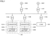
- FIG. 1 is a diagram illustrating an example of a system 105 to which a storage battery system 130 according to the present embodiment is interconnected. Each configuration of storage battery system 130 and an outline of an operation of storage battery system 130 will be described with reference to FIG. 1 .
- system 105 is an alternating current power system.
- a generator 100 is interconnected to system 105 via a transformer 110.
- generator 100 includes a rotary machine that rotates by steam, gas, hydraulic power, or the like and converts rotational energy into electric energy.
- Generator 100 supplies electric energy generated by rotary machine to system 105 via transformer 110.
- a part of the energy supplied to system 105 by generator 100 is charged in a storage battery 122 in storage battery system 130.
- the remainder of the energy supplied to system 105 by generator 100 is consumed by a load 150.
- the electric energy per unit time is referred to as power, and a frequency of system 105 is kept constant when a balance between demand and supply of the power is balanced.
- power demand exceeds power supply
- the frequency of system 105 decreases, and when the power supply exceeds the power demand, the frequency of the system increases.
- the generator is provided with a speed governor, and the generator controls a rotation speed of the rotary machine by the speed governor to maintain the balance between the power demand and the power supply and suppress a fluctuation in the frequency of system 105.
- Transformer 110 converts a voltage between power lines.
- a transformer 110C converts a voltage between a generator 100X and system 105.
- a transformer 110A converts a voltage between a storage battery unit 120A and system 105.
- Transformer 110 can be of any size and withstand any voltage depending on a place to be used, application, and the like.
- transformer 100X before generator 110X can be larger in scale than transformer 110A before storage battery unit 120A.
- transformer 110 may include either or both of an AC/AC converter for performing an alternating current (AC) transformation or/and a DC/AC (AC/DC) converter for converting direct current (DC) and AC.
- Storage battery unit 120A outputs constant active power on the basis of the frequency of system 105 being lower than a first threshold value set in advance. Specifically, in a first step, a converter 121A detects the voltage and frequency of system 105 by a frequency detector (not shown). At that time, converter 121A may detect the voltage and frequency of the power line of storage battery unit 120A of transformer 110A by the frequency detector.
- converter 121A determines whether the frequency of system 105 is lower than the first threshold value set in advance. When determining that the frequency of system 105 is lower than the first threshold value, converter 121A switches a circuit inside converter 121A such that constant active power is output from a storage battery 122A toward system 105. Otherwise, converter 121A maintains the circuit inside converter 121A such that storage battery 122A is charged.
- converter 121B detects the voltage and frequency of system 105 by the frequency detector (not shown). At that time, converter 121B may detect the voltage and frequency of the power line of storage battery unit 120B of transformer 110B by the frequency detector. Note that processing of the third step may be executed at least before processing of the second step.
- storage battery unit 120B may output the active power proportional to a deviation between the frequency of system 105 and a reference frequency. In another aspect, storage battery unit 120B may output the active power based on a value obtained by proportional integration of the deviation between the frequency of system 105 and the reference frequency.
- the "reference frequency" is, for example, a representative value of the frequency in a normal state in system 105.
- only storage battery unit 120A when the frequency of system 105 decreases only within a certain range (when the frequency of system 105 decreases to less than the first threshold value and greater than or equal to the second threshold value), only storage battery unit 120A outputs constant active power.
- storage battery unit 120A When the frequency of system 105 decreases beyond the certain range (when the frequency of system 105 decreases to less than the second threshold value), storage battery unit 120A outputs constant active power and storage battery unit 120B also outputs active power that changes on the basis of the frequency of system 105 and the reference frequency to suppress a sharp decrease in the frequency of system 105.
- the frequency of system 105 may vibrate or diverge. This is because when the frequency of system 105 rises and falls around the reference frequency, the active power output from storage battery unit 120B also rises and falls in proportion to the frequency of system 105. Therefore, storage battery unit 120B suppresses vibration or divergence of the frequency of system 105 by stopping the output of the active power before storage battery unit 120A does.
- converter 121B determines whether the frequency of system 105 is greater than or equal to the second threshold value. When determining that the frequency of system 105 is greater than or equal to the second threshold value, converter 121B switches the circuit inside converter 121B to block the output of active power from storage battery 122B. Otherwise, converter 121B maintains the circuit inside converter 121B such that active power is output from storage battery 122B. In one aspect, converter 121B may switch the circuit inside converter 121B so as to gradually decrease and stop the output of active power from storage battery 122B.
- storage battery unit 120B that outputs active power that fluctuates on the basis of the change in the frequency of system 105 stops power supply to system 105 before storage battery unit 120A, and thus the frequency of system 105 can be suppressed from vibrating or diverging around the reference frequency.
- storage battery unit 120 having a function of outputting constant active power regardless of the change in the frequency of system 105 is referred to as “storage battery unit 120A”.
- storage battery unit 120B having a function of outputting active power that fluctuates on the basis of the change in the frequency of system 105 is referred to as “storage battery unit 120B”.
- controller 201 In a case where controller 201 executes software, controller 201 includes a central processing unit (CPU) (not shown) and a random access memory (RAM) (not shown). Controller 201 may further include a read only memory (ROM) (not shown).
- CPU central processing unit
- RAM random access memory
- ROM read only memory
- the CPU executes or refers to various programs and data read into the RAM.
- the RAM stores a program executed by the CPU and the data referred to by the CPU.
- the RAM may be a dynamic random access memory (DRAM) or a static random access memory (SRAM).
- the ROM is a nonvolatile memory, and may store the program executed by the CPU. In this case, the CPU executes the program read from the ROM to the RAM.
- the ROM may be an erasable programmable read only memory (EPROM), an electrically erasable programmable read-only memory (EEPROM), or a flash memory.
- the storage can store any programs and data that the CPU executes or refers to.
- the storage may be a hard disk drive (HDD) or a solid state drive (SSD).
- the CPU can read various programs from the storage into the RAM as necessary and execute the read programs.
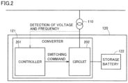
- Controller 201 detects the voltage and frequency of the power line between transformer 110 and storage battery unit 120 by the frequency detector. Controller 201 can detect the voltage and frequency of system 105 on the basis of the detected frequency. In one aspect, controller 201 may directly detect the voltage and frequency of system 105. In another aspect, the frequency detector may be built in controller 201 or may be provided outside controller 201.
- Circuit 202 controls a flow of power between storage battery 122 and system 105.
- Circuit 202 can include, for example, an inverter (DC/AC converter) and a converter (AC/DC converter).
- circuit 202 may include a DC/DC converter.
- circuit 202 may include an AC/AC converter.
- Controller 201 outputs a switching command that controls the inverter, the converter, or a peripheral circuit of the inverter and the converter to circuit 202 on the basis of a detection result of the frequency detector.
- controller 201 can adjust a direction of the flow of power or an amount of power between storage battery 122 and system 105.
- FIG. 3 is a diagram illustrating an example of a flow of the data between the modules inside controller 201 in converter 121.
- Each configuration illustrated in FIG. 3 may be a program module executed by controller 201, may be hardware incorporated in controller 201, or may be a combination thereof. Some of the configurations may be provided outside controller 201.
- a frequency detector 301 detects an interconnection point voltage 311.
- Frequency detector 301 converts interconnection point voltage 311 into a rotating coordinate system, and at the same time, detects a frequency 312 of the interconnection point.
- the "interconnection point” is a connection point between storage battery unit 120 and system 105. In other words, the interconnection point refers to a vicinity of transformer 110 between storage battery unit 120 and system 105.
- Frequency detector 301 outputs frequency 312 of the interconnection point to active power command value generator 302.
- Active power command value generator 302 generates an active power command value 313 in accordance with frequency 312 of the interconnection point having been input. Active power command value generator 302 outputs active power command value 313 having been generated to an active power controller 303.
- Active power controller 303 generates an active current command value 314 such that active power whose feedback has been detected by controller 201 follows active power command value 313. Active power controller 303 outputs active current command value 314 to an active current controller 304.
- Active current controller 304 generates a modulation factor 315 such that active current whose feedback has been detected by controller 201 follows active current command value 314. Active current controller 304 outputs modulation factor 315 to a pulse width modulation (PWM) processor 305.
- PWM pulse width modulation
- PWM processor 305 converts modulation factor 315 into an on-off command 316 of each switch included in circuit 202. PWM processor 305 outputs on-off command 316 (switching command) to circuit 202. Each switch of circuit 202 switches on-off operation in accordance with the on-off command generated by controller 201.
- controller 201 can include hardware and software for implementing a reactive power control or voltage control function.
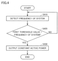
- FIG. 4 is a diagram illustrating a first example of the operation procedure of storage battery unit 120A.
- controller 201 of storage battery unit 120A may read a program for performing processing in FIG. 4 from the ROM or the storage into the RAM and execute the program.
- a part or all of the processing can be implemented as a combination of circuit elements configured to execute the processing.
- controller 201 detects the frequency of system 105 by frequency detector 301. In step S420, controller 201 determines whether the detected frequency of system 105 is less than the first threshold value. In one aspect, controller 201 may read data of the first threshold value from the ROM or the storage to the RAM and refer to the data.
- controller 201 When determining that the detected frequency of system 105 is less than the first threshold value (YES in step S420), controller 201 shifts the control to step S430. Otherwise (NO in step S420), controller 201 shifts the control to step S410.
- step S430 controller 201 outputs a switching command to circuit 202 so as to output constant active power from storage battery 122A to system 105.
- Circuit 202 turns on or off a switch inside the circuit 202 in response to the input switching command.
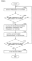
- FIG. 5 is a diagram illustrating an example of an operation procedure of storage battery unit 120B.
- controller 201 of storage battery unit 120B may read a program for performing processing in FIG. 5 from the ROM or the storage into the RAM and execute the program.
- a part or all of the processing can be implemented as a combination of circuit elements configured to execute the processing.
- controller 201 detects the frequency of system 105 by frequency detector 301. In step S520, controller 201 determines whether the detected frequency of system 105 is less than the second threshold value. In one aspect, controller 201 may read data of the second threshold value from the ROM or the storage to the RAM and refer to the read data of the second threshold value.
- controller 201 When determining that the detected frequency of system 105 is less than the second threshold value (YES in step S520), controller 201 shifts the control to step S530. Otherwise (NO in step S520), controller 201 shifts the control to step S510.
- controller 201 calculates a deviation between the reference frequency and the detected frequency of system 105.
- controller 201 outputs a switching command to circuit 202 such that the active power proportional to the deviation between the reference frequency and the detected frequency of system 105 is output from storage battery 122B to system 105.
- Circuit 202 turns on or off a switch inside the circuit 202 in response to the input switching command.
- controller 201 outputs a switching command to circuit 202 such that active power based on a value obtained by proportional integration of the deviation between the detected frequency of system 105 and the reference frequency is output from storage battery 122B to system 105.
- step S550 controller 201 determines whether the detected frequency of system 105 is greater than or equal to the second threshold value. In other words, controller 201 determines whether the decreased frequency of system 105 has recovered to the second threshold value or more.
- controller 201 shifts the control to step S560. Otherwise (NO in step S550), controller 201 shifts the control to step S510.
- controller 201 outputs a switching command to circuit 202 so as to stop the output of active power from storage battery 122B to system 105.
- controller 201 may output a switching command to circuit 202 so as to gradually decrease and stop the output of active power from storage battery 122B to system 105.
- FIG. 6 is a first example of the simulation result of the change in the frequency of system 105 in a case where storage battery system 130 operates when generator 100 is disconnected and the frequency of system 105 drops.
- the reference frequency is 50 Hz.
- a graph 610 illustrates a change amount of the frequency of system 105 in a case where storage battery system 130 includes only storage battery unit 120B.
- a graph 620 illustrates a change amount of the frequency of system 105 in a case where storage battery system 130 includes storage battery unit 120A and storage battery unit 120B.
- storage battery system 130 includes storage battery unit 120A that outputs active power without depending on the frequency, and thus can suppress occurrence of vibration and divergence of the frequency of system 105 and stabilize system 105.
- storage battery unit 120B After the decrease in the frequency of system 105 is suppressed by the output of the active power by storage battery unit 120A, storage battery unit 120B outputs the active power corresponding to the frequency of system 105, and thus the balance between the power supply and the power demand in the system can be adjusted.
- the frequency of the system 105 becomes greater than or equal to the second threshold value, storage battery unit 120B gradually decreases or stops the output of the active power.
- FIG. 7 is a second example of the simulation result of the change in the frequency of system 105 in a case where storage battery system 130 operates when generator 100 is disconnected and the frequency of system 105 drops.
- reference frequency is 50 Hz
- storage battery unit 120B outputs active power corresponding to a value obtained by proportional integration of the deviation between the frequency of system 105 and the reference frequency.
- a graph 710 illustrates a change amount of the frequency of system 105 in a case where storage battery system 130 includes only storage battery unit 120B.
- a graph 720 illustrates a change amount of the frequency of system 105 in a case where storage battery system 130 includes storage battery unit 120A and storage battery unit 120B.
- storage battery system 130 includes not only storage battery unit 120B that changes the output of the active power on the basis of the proportion of the deviation between the frequency of system 105 and the reference frequency but also storage battery unit 120A that outputs constant active power. It is therefore possible to suppress the occurrence of vibration and divergence of the frequency of system 105 due to excessive output of the active power and stabilize system 105.
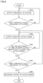
- FIG. 8 is a diagram illustrating a second example of the operation procedure of storage battery unit 120A.
- controller 201 of storage battery unit 120A may read a program for performing processing in FIG. 8 from the ROM or the storage into the RAM and execute the program.
- a part or all of the processing can be implemented as a combination of circuit elements configured to execute the processing.
- controller 201 detects the frequency of system 105 by frequency detector 301.
- controller 201 determines whether the detected frequency of system 105 is less than the first threshold value.
- controller 201 When determining that the detected frequency of system 105 is less than the first threshold value (YES in step S820), controller 201 shifts the control to step S830. Otherwise (NO in step S820), controller 201 shifts the control to step S810.
- step S830 controller 201 outputs a switching command to circuit 202 so as to output constant active power from storage battery 122A to system 105.
- Circuit 202 turns on or off a switch inside circuit 202 in response to the input switching command.
- step S840 controller 201 determines whether storage battery 122A has output constant active power for a certain period of time set in advance or more. When determining that storage battery 122A has output constant active power for a certain period of time or more (YES in step S840), controller 201 shifts the control to step S850. Otherwise (NO in step S840), controller 201 shifts the control to step S830.
- controller 201 determines whether the frequency of system 105 is greater than or equal to the third threshold value.
- the third threshold value may be a value greater than or equal to the first threshold value.
- controller 201 may read data of the third threshold value from the ROM or the storage to the RAM and refer to the read data.
- controller 201 When determining that the frequency of system 105 is greater than or equal to the third threshold value (YES in step S850), controller 201 shifts the control to step S860. Otherwise (NO in step S850), controller 201 shifts the control to step S830.
- controller 201 outputs a switching command to circuit 202 so as to gradually approximate the constant active power output from storage battery 122A to system 105 to zero.
- the active power gradually approaches zero with a slow time constant regardless of depending on the frequency of system 105.
- a method of approximating the current output to zero in a ramp state is considered.
- the balance between the demand and the supply of power may be lost due to the decrease in the output of the active power of storage battery unit 120A, the balance between the power demand and the power supply can be adjusted by an increase in the output of storage battery unit 120B and generator 100 connected to the system.
- storage battery unit 120A can decrease the output of the active power before a charge state of storage battery 122A becomes zero.
- Storage battery unit 120A can suppress a sudden collapse of the balance between the power demand and the power supply by gradually approximating the output of the active power to zero at a slow time constant.
- controller 201 may gradually approximate the active power output value to zero only when output time of the active power exceeds a certain period of time and the frequency of system 105 is greater than or equal to the third threshold value. In another aspect, when output time of the active power exceeds a certain period of time, controller 201 may gradually approximate the active power output value to zero whether or not the frequency of system 105 is greater than or equal to the third threshold value.
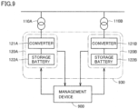
- FIG. 9 is a diagram illustrating a second example of a storage battery system according to the present embodiment.
- a storage battery system 930 is different from storage battery system 130 illustrated in FIG. 1 in that storage battery system 930 cooperates with a management device 900.
- Management device 900 is connected to each of the plurality of storage battery units 120 via a communication path.
- the communication path may be wireless or wired.
- Management device 900 can acquire state information from each of the plurality of storage battery units 120 and transmit a command to each of the plurality of storage battery units 120 at regular time intervals.
- the “state information” herein may include the charge state of each storage battery unit 120, a history of input and output of active power, and the like.
- the "command” herein includes assignment of a role of each storage battery unit 120, the third threshold value for storage battery unit 120 selected as storage battery unit 120A, setting of active power output from each storage battery unit 120, and the like.
- Management device 900 can change a type, parameter, and the like of information included in the command on the basis of the state information.
- management device 900 acquires state information from each of the plurality of storage battery units 120, and transmits a command to assign a role to each storage battery unit 120 on the basis of the state information.
- management device 900 selects one of two storage battery units 120 as storage battery unit 120A and selects the other as storage battery unit 120B.
- Management device 900 may transmit a command to update the third threshold value to storage battery unit 120A on the basis of the state information acquired from selected storage battery unit 120A and/or 120B.
- management device 900 may select storage battery unit 120 having a relatively small output of the current active power as storage battery unit 120A.
- the charge state of storage battery unit 120A becomes 0%, the balance between the power demand and the power supply is greatly lost, and thus, it is desirable that storage battery unit 120 selected as storage battery unit 120A maintains a certain charge state. Therefore, management device 900 assigns the role of storage battery unit 120A to appropriate storage battery unit 120 on the basis of an output state, the charge state, and the like of the active power of each storage battery unit 120.
- Management device 900 can select storage battery unit 120B from among storage battery units 120 having a relatively small output of the current active power and maintaining a certain charge state among storage battery units 120 that have not been selected as storage battery unit 120A.
- Management device 900 transmits the third threshold value to storage battery unit 120A.
- storage battery unit 120A continues to output the active power until the frequency of system 105 reaches the received third threshold value.
- Management device 900 can determine the setting of the active power output from each of storage battery units 120A and 120B on the basis of the charge state of each of storage battery units 120A and 120B or the current output state of the active power.
- Management device 900 transmits these settings to each of storage battery units 120A and 120B. Through this processing, management device 900 can manage a total output of the active power of storage battery system 930 as a whole.
- management device 900 may manage a plurality of storage battery systems 930.
- a plurality of management devices 900 may divide and manage the plurality of storage battery systems 930.
- a higher-level management device for managing the plurality of management devices 900 may be installed.
- management device 900 may select the plurality of storage battery units 120 as storage battery unit 120A, or may select the plurality of storage battery units 120 as storage battery unit 120.
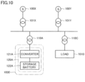
- FIG. 10 is a diagram illustrating a third example of the storage battery system according to the present embodiment.
- a storage battery system 1030 in FIG. 10 is different from storage battery systems 130 and 930 in that storage battery system 1030 includes only storage battery unit 120A and does not include storage battery unit 120B.
- Storage battery system 1030 includes only storage battery unit 120A that outputs constant active power without depending on the frequency of system 105, and thus can suppress vibration and divergence of the frequency of system 105.
- storage battery systems 130, 930, and 1030 include at least storage battery 122A that always outputs the constant active power regardless of the fluctuation in the frequency of system 105.
- storage battery system 130 can suppress vibration and divergence of the frequency of system 105.
- Storage battery system 130 in one aspect includes storage battery unit 120A and storage battery unit 120B.
- storage battery unit 120A When storage battery unit 120A outputs the constant active power, storage battery unit 120B also outputs active power that changes on the basis of the frequency of system 105 and the reference frequency. In this configuration, storage battery system 130 can suppress a sharp decrease and divergence of the frequency of system 105.
- Storage battery system 930 in another aspect transmits a command to each storage battery unit 120 on the basis of the state information of each storage battery unit 120 in cooperation with management device 900.
- management device 900 can select appropriate storage battery unit 120 as storage battery units 120A and 120B.
Landscapes
- Engineering & Computer Science (AREA)
- Power Engineering (AREA)
- Physics & Mathematics (AREA)
- Microelectronics & Electronic Packaging (AREA)
- Manufacturing & Machinery (AREA)
- Chemical & Material Sciences (AREA)
- Chemical Kinetics & Catalysis (AREA)
- Electrochemistry (AREA)
- General Chemical & Material Sciences (AREA)
- Nonlinear Science (AREA)
- General Physics & Mathematics (AREA)
- Supply And Distribution Of Alternating Current (AREA)
Claims (15)
- Speicherbatteriesystem (130), umfassend eine erste Speicherbatterieeinheit (120A) und eine zweite Speicherbatterieeinheit (120B), wobeidie erste Speicherbatterieeinheit (120A) Folgendes umfasst:- einen ersten Wandler (121A) zum Umwandeln von Wechselstrom und Gleichstrom,- eine erste Speicherbatterie (122A) und- eine erste Steuerung zum Steuern des ersten Wandlers (121A),die erste Speicherbatterieeinheit (120A) mit einem System zum Zuführen von Leistung verbunden ist, unddie erste Steuerung eine Frequenz des Systems erfasst und den ersten Wandler (121A) für die erste Speicherbatterie (122A) auf Grundlage dessen, dass die Frequenz des Systems unter einen ersten Schwellenwert fällt, steuert, um konstante Wirkleistung an das System abzugeben, wobei die zweite Speicherbatterieeinheit (120B) Folgendes umfasst:- einen zweiten Wandler (121B) zum Umwandeln von Wechselstrom und Gleichstrom,- eine zweite Speicherbatterie (122B) und- eine zweite Steuerung zum Steuern des zweiten Wandlers (121B), und wobeidie zweite Speicherbatterieeinheit (120B) mit dem System verbunden ist und die zweite Steuerung eine Frequenz des Systems erfasst und den zweiten Wandler (121B) für die zweite Speicherbatterie (122B) auf Grundlage dessen, dass die Frequenz des Systems unter einen zweiten Schwellenwert fällt, steuert, um Wirkleistung, die gemäß einer Differenz zwischen der Frequenz des Systems, die erfasst wurde, und einer Referenzfrequenz schwankt, an das System abzugeben, dadurch gekennzeichnet, dass der zweite Schwellenwert niedriger als der erste Schwellenwert ist.
- Speicherbatteriesystem (130) nach Anspruch 1, wobeidie erste Steuerung bestimmt, ob ein vorbestimmter Zeitraum ab einem Zeitpunkt verstrichen ist, an dem die erste Speicherbatterie (122A) mit dem Abgeben von Wirkleistung beginnt, undden ersten Wandler (121A) auf Grundlage dessen, dass der vorbestimmte Zeitraum verstrichen ist, steuert, um die Wirkleistungsabgabe von der ersten Speicherbatterie (122A) zu verringern.
- Speicherbatteriesystem (130) nach Anspruch 1, wobeidie erste Steuerung die Frequenz des Systems erfasst, nachdem die erste Speicherbatterie (122A) mit dem Abgeben von Wirkleistung beginnt, undden ersten Wandler (121A) auf Grundlage dessen, dass die Frequenz des Systems größer als oder gleich einem dritten Schwellenwert ist, der den ersten Schwellenwert überschreitet, steuert, um die Wirkleistungsabgabe von der ersten Speicherbatterie (122A) zu verringern.
- Speicherbatteriesystem (130) nach einem der Ansprüche 1 bis 3, wobei die zweite Steuerung den zweiten Wandler (121B) auf Grundlage dessen, dass die Frequenz des Systems größer als oder gleich dem zweiten Schwellenwert ist, steuert, um die Wirkleistungsabgabe von der zweiten Speicherbatterie (122B) anzuhalten.
- Speicherbatteriesystem (130) nach einem der Ansprüche 1 bis 3, wobei
die zweite Steuerung den zweiten Wandler (121B) steuert, um die Wirkleistungsabgabe von der zweiten Speicherbatterie (122B) anzuhalten, bevor die erste Steuerung die Wirkleistungsabgabe von der ersten Speicherbatterie (122A) anhält. - Speicherbatteriesystem (130) nach Anspruch 4 oder 5, wobei
die zweite Speicherbatterie (122B) eine Wirkleistung proportional zu einer Abweichung zwischen der Frequenz des Systems und der Referenzfrequenz abgibt. - Speicherbatteriesystem (130) nach Anspruch 4 oder 5, wobei
die zweite Speicherbatterie (122B) auf Grundlage eines Werts, der durch proportionale Integration einer Abweichung zwischen der Frequenz des Systems und der Referenzfrequenz erlangt wird, Wirkleistung abgibt. - Speicherbatteriesystem (130) nach einem der Ansprüche 4 bis 7, ferner umfassend:- eine Verwaltungsvorrichtung zum Kommunizieren mit einer Vielzahl von Speicherbatterieeinheiten, die mit dem System verbunden sind, wobeidie Verwaltungsvorrichtung eine erste Anweisung an eine Speicherbatterieeinheit überträgt, die aus der Vielzahl von Speicherbatterieeinheiten ausgewählt ist, die mit dem System verbunden sind, um die Speicherbatterieeinheit als die erste Speicherbatterieeinheit (120A) zu betreiben, und eine zweite Anweisung an eine andere Speicherbatterieeinheit überträgt, die aus der Vielzahl von Speicherbatterieeinheiten ausgewählt ist, die mit dem System verbunden sind, um die andere Speicherbatterieeinheit als die zweite Speicherbatterieeinheit (120B) zu betreiben.
- Speicherbatteriesystem (130) nach Anspruch 8, wobei
die Verwaltungsvorrichtung die Speicherbatterieeinheit, die als die erste Speicherbatterieeinheit (120A) zu betreiben ist, und die Speicherbatterieeinheit, die als die zweite Speicherbatterieeinheit (120B) zu betreiben ist, aus der Vielzahl von Speicherbatterieeinheiten, die mit dem System verbunden sind, auf Grundlage eines Ladezustands von jeder der Vielzahl von Speicherbatterieeinheiten, die mit dem System verbunden sind, auswählt. - Speicherbatteriesystem (130) nach Anspruch 8 oder 9, wobei
die Verwaltungsvorrichtung die Speicherbatterieeinheit, die als die erste Speicherbatterieeinheit (120A) zu betreiben ist, und die Speicherbatterieeinheit, die als die zweite Speicherbatterieeinheit (120B) zu betreiben ist, aus der Vielzahl von Speicherbatterieeinheiten, die mit dem System verbunden sind, auf Grundlage einer Wirkleistungsabgabe von jeder der Vielzahl von Speicherbatterieeinheiten, die mit dem System verbunden sind, auswählt. - Speicherbatteriesystem (130) nach einem der Ansprüche 8 bis 10, wobei
die Verwaltungsvorrichtung an die erste Speicherbatterieeinheit (120A) eine Anweisung zum Einstellen eines Werts der Wirkleistungsabgabe von der ersten Speicherbatterie (122A) überträgt. - Speicherbatteriesystem (130) nach Anspruch 11, wobei
die Verwaltungsvorrichtung den Wert der Wirkleistungsabgabe von der ersten Speicherbatterie (122A) auf Grundlage eines Ladezustands der ersten Speicherbatterie (122A) bestimmt. - Verfahren zum Unterdrücken einer Frequenzschwankung eines Wechselstromleistungssystems, wobei das Verfahren Folgendes umfasst:Erfassen der Frequenz des Systems;Abgeben von konstanter Wirkleistung von einer ersten Speicherbatterieeinheit (120A), die mit dem System verbunden ist, an das System auf Grundlage dessen, dass die Frequenz des Systems unter einen ersten Schwellenwert fällt; undAbgeben von Wirkleistung, die gemäß einer Differenz zwischen der Frequenz des Systems, die erfasst wurde, und einer Referenzfrequenz schwankt, von einer zweiten Speicherbatterieeinheit (120B), die mit dem System verbunden ist, an das System auf Grundlage dessen, dass die Frequenz des Systems unter einen zweiten Schwellenwert fällt,dadurch gekennzeichnet, dass der zweite Schwellenwert niedriger als der erste Schwellenwert ist.
- Verfahren nach Anspruch 13, ferner umfassend:
Bestimmen, ob ein vorbestimmter Zeitraum ab einem Zeitpunkt verstrichen ist, an dem die erste Speicherbatterieeinheit (120A) mit dem Abgeben von Wirkleistung beginnt, und Verringern der Wirkleistungsabgabe von der ersten Speicherbatterieeinheit (120A) auf Grundlage dessen, dass der vorbestimmte Zeitraum verstrichen ist. - Verfahren nach Anspruch 13, ferner umfassend:Erfassen der Frequenz des Systems, nachdem die erste Speicherbatterieeinheit (120A) mit dem Abgeben von Wirkleistung beginnt, undVerringern der Wirkleistungsabgabe von der ersten Speicherbatterie (120A) auf Grundlage dessen, dass die Frequenz des Systems größer als oder gleich einem dritten Schwellenwert ist, der den ersten Schwellenwert überschreitet.
Applications Claiming Priority (1)
| Application Number | Priority Date | Filing Date | Title |
|---|---|---|---|
| PCT/JP2020/014491 WO2021199125A1 (ja) | 2020-03-30 | 2020-03-30 | 蓄電池システム、および交流電力の系統の周波数の変動を抑制する方法 |
Publications (3)
| Publication Number | Publication Date |
|---|---|
| EP4131764A1 EP4131764A1 (de) | 2023-02-08 |
| EP4131764A4 EP4131764A4 (de) | 2023-05-31 |
| EP4131764B1 true EP4131764B1 (de) | 2024-06-05 |
Family
ID=76310316
Family Applications (1)
| Application Number | Title | Priority Date | Filing Date |
|---|---|---|---|
| EP20928074.2A Active EP4131764B1 (de) | 2020-03-30 | 2020-03-30 | Speicherbatteriesystem und verfahren zur unterdrückung von frequenzschwankungen eines wechselstromsystems |
Country Status (4)
| Country | Link |
|---|---|
| US (1) | US11973347B2 (de) |
| EP (1) | EP4131764B1 (de) |
| JP (1) | JP6888173B1 (de) |
| WO (1) | WO2021199125A1 (de) |
Families Citing this family (4)
| Publication number | Priority date | Publication date | Assignee | Title |
|---|---|---|---|---|
| EP4176505A1 (de) * | 2020-07-01 | 2023-05-10 | Vestas Wind Systems A/S | Batterieprüfung im betrieb |
| JP7786271B2 (ja) * | 2022-03-18 | 2025-12-16 | 株式会社豊田中央研究所 | 分散電源システム |
| JP7797343B2 (ja) * | 2022-09-15 | 2026-01-13 | 株式会社東芝 | 需給電装置、発電システムおよび制御方法 |
| CN115811070A (zh) * | 2022-12-05 | 2023-03-17 | 华北电力大学 | 辅助火电机组调频的飞轮储能自适应容量配置方法及系统 |
Family Cites Families (11)
| Publication number | Priority date | Publication date | Assignee | Title |
|---|---|---|---|---|
| JP2011167014A (ja) * | 2010-02-12 | 2011-08-25 | Tokyo Electric Power Co Inc:The | コンバータ制御装置 |
| JP5436400B2 (ja) * | 2010-12-07 | 2014-03-05 | 東北電力株式会社 | 電力系統安定化装置 |
| US20130076131A1 (en) | 2011-04-08 | 2013-03-28 | Panasonic Corporation | Distributed power generation system and operation method thereof |
| WO2013042475A1 (ja) | 2011-09-22 | 2013-03-28 | 日本電気株式会社 | 電池制御システム、電池制御装置、電池制御方法および記録媒体 |
| JP6232899B2 (ja) | 2013-10-07 | 2017-11-22 | 富士電機株式会社 | 電力補償装置 |
| US9583945B2 (en) | 2014-06-09 | 2017-02-28 | Panasonic Intellectual Property Management Co., Ltd. | Frequency control method and frequency control apparatus |
| KR102400502B1 (ko) * | 2015-09-24 | 2022-05-20 | 삼성에스디아이 주식회사 | 에너지 저장 시스템 |
| US20170214251A1 (en) * | 2016-01-21 | 2017-07-27 | General Electric Company | Energy Storage Systems With Enhanced Storage and Discharge Response Allocation |
| JP7120600B2 (ja) | 2018-03-13 | 2022-08-17 | 日本電気株式会社 | 処理装置、処理方法及びプログラム |
| JP7057250B2 (ja) * | 2018-08-06 | 2022-04-19 | 株式会社Nttファシリティーズ | 周波数制御システム |
| JP2020025399A (ja) * | 2018-08-07 | 2020-02-13 | 株式会社Nttファシリティーズ | 周波数制御システム |
-
2020
- 2020-03-30 US US17/795,542 patent/US11973347B2/en active Active
- 2020-03-30 WO PCT/JP2020/014491 patent/WO2021199125A1/ja not_active Ceased
- 2020-03-30 EP EP20928074.2A patent/EP4131764B1/de active Active
- 2020-03-30 JP JP2020547020A patent/JP6888173B1/ja active Active
Also Published As
| Publication number | Publication date |
|---|---|
| WO2021199125A1 (ja) | 2021-10-07 |
| US20230075738A1 (en) | 2023-03-09 |
| JPWO2021199125A1 (de) | 2021-10-07 |
| EP4131764A1 (de) | 2023-02-08 |
| EP4131764A4 (de) | 2023-05-31 |
| JP6888173B1 (ja) | 2021-06-16 |
| US11973347B2 (en) | 2024-04-30 |
Similar Documents
| Publication | Publication Date | Title |
|---|---|---|
| EP4131764B1 (de) | Speicherbatteriesystem und verfahren zur unterdrückung von frequenzschwankungen eines wechselstromsystems | |
| EP3345275B1 (de) | Verfahren und vorrichtung zur steuerung des energieflusses zwischen ungleichen energiespeichereinrichtungen | |
| EP1780860B1 (de) | Anordnung und Verfahren zum Leistungssteuern in einem Energieversorgungssystem | |
| EP2362521B1 (de) | Frequenzsteuerung für eine Energieerzeugung | |
| EP2839562A1 (de) | Verfahren und system zur leistungsregelung eines stromnetzes | |
| CN105339605A (zh) | 混合发电厂 | |
| EP4142132B1 (de) | Stromversorgungssystem | |
| US11056885B2 (en) | Method of providing power support to an electrical power grid | |
| Jawad et al. | Optimal sizing of BESS for attaining frequency stability under high PV penetration | |
| US20250239862A1 (en) | Systems and methods for paralleling multiple power sources | |
| JP2007124780A (ja) | 蓄電システム及び風力発電所 | |
| JP2017070130A (ja) | 電力制御システム及び電力制御方法 | |
| Nerkar et al. | An analysis of the impact on frequency response with penetration of RES in power system and modified virtual inertia controller | |
| US10574056B1 (en) | Communication enabled fast-acting imbalance reserve | |
| JP7139585B2 (ja) | 電力変換器の制御装置、制御方法、制御プログラム | |
| JP2022517732A (ja) | エネルギー生成プラントを用いて交流電圧システムに調整電力を提供するための方法 | |
| Xu et al. | MTDC systems for frequency support base on DC voltage manipulation | |
| JP2024017513A (ja) | 分散型電源システム及び分散型電源の制御方法 | |
| JP2025011933A (ja) | 蓄電装置の制御方法および蓄電装置 | |
| US20250273962A1 (en) | Method and device for controlling microgrid of hydrometallurgical plant based on energy storage frequency converter | |
| KR102917366B1 (ko) | Ess 통합 운영 자동화 시스템 및 방법 | |
| KR102933334B1 (ko) | Ess 드룹 제어 장치, 이를 포함하는 ess 드룹 제어 시스템 및 이의 제어방법 | |
| US20250392126A1 (en) | Essential and curtailable load distribution optimization in microgrid controller | |
| Chethan et al. | Grid Synchronization of the VSC‐HVDC System Based on Virtual Synchronous Generator Control Strategy | |
| KR20250096077A (ko) | 독립형 전력 시스템 및 그의 동작 방법 |
Legal Events
| Date | Code | Title | Description |
|---|---|---|---|
| STAA | Information on the status of an ep patent application or granted ep patent |
Free format text: STATUS: THE INTERNATIONAL PUBLICATION HAS BEEN MADE |
|
| PUAI | Public reference made under article 153(3) epc to a published international application that has entered the european phase |
Free format text: ORIGINAL CODE: 0009012 |
|
| STAA | Information on the status of an ep patent application or granted ep patent |
Free format text: STATUS: REQUEST FOR EXAMINATION WAS MADE |
|
| 17P | Request for examination filed |
Effective date: 20220922 |
|
| AK | Designated contracting states |
Kind code of ref document: A1 Designated state(s): AL AT BE BG CH CY CZ DE DK EE ES FI FR GB GR HR HU IE IS IT LI LT LU LV MC MK MT NL NO PL PT RO RS SE SI SK SM TR |
|
| A4 | Supplementary search report drawn up and despatched |
Effective date: 20230502 |
|
| RIC1 | Information provided on ipc code assigned before grant |
Ipc: H02J 3/32 20060101ALI20230424BHEP Ipc: H02M 7/48 20070101AFI20230424BHEP |
|
| DAV | Request for validation of the european patent (deleted) | ||
| DAX | Request for extension of the european patent (deleted) | ||
| GRAP | Despatch of communication of intention to grant a patent |
Free format text: ORIGINAL CODE: EPIDOSNIGR1 |
|
| STAA | Information on the status of an ep patent application or granted ep patent |
Free format text: STATUS: GRANT OF PATENT IS INTENDED |
|
| INTG | Intention to grant announced |
Effective date: 20240111 |
|
| GRAS | Grant fee paid |
Free format text: ORIGINAL CODE: EPIDOSNIGR3 |
|
| GRAA | (expected) grant |
Free format text: ORIGINAL CODE: 0009210 |
|
| STAA | Information on the status of an ep patent application or granted ep patent |
Free format text: STATUS: THE PATENT HAS BEEN GRANTED |
|
| AK | Designated contracting states |
Kind code of ref document: B1 Designated state(s): AL AT BE BG CH CY CZ DE DK EE ES FI FR GB GR HR HU IE IS IT LI LT LU LV MC MK MT NL NO PL PT RO RS SE SI SK SM TR |
|
| REG | Reference to a national code |
Ref country code: CH Ref legal event code: EP |
|
| REG | Reference to a national code |
Ref country code: DE Ref legal event code: R096 Ref document number: 602020032148 Country of ref document: DE |
|
| REG | Reference to a national code |
Ref country code: IE Ref legal event code: FG4D |
|
| REG | Reference to a national code |
Ref country code: SE Ref legal event code: TRGR |
|
| REG | Reference to a national code |
Ref country code: LT Ref legal event code: MG9D |
|
| PG25 | Lapsed in a contracting state [announced via postgrant information from national office to epo] |
Ref country code: BG Free format text: LAPSE BECAUSE OF FAILURE TO SUBMIT A TRANSLATION OF THE DESCRIPTION OR TO PAY THE FEE WITHIN THE PRESCRIBED TIME-LIMIT Effective date: 20240605 |
|
| REG | Reference to a national code |
Ref country code: NL Ref legal event code: MP Effective date: 20240605 |
|
| PG25 | Lapsed in a contracting state [announced via postgrant information from national office to epo] |
Ref country code: HR Free format text: LAPSE BECAUSE OF FAILURE TO SUBMIT A TRANSLATION OF THE DESCRIPTION OR TO PAY THE FEE WITHIN THE PRESCRIBED TIME-LIMIT Effective date: 20240605 Ref country code: FI Free format text: LAPSE BECAUSE OF FAILURE TO SUBMIT A TRANSLATION OF THE DESCRIPTION OR TO PAY THE FEE WITHIN THE PRESCRIBED TIME-LIMIT Effective date: 20240605 |
|
| PG25 | Lapsed in a contracting state [announced via postgrant information from national office to epo] |
Ref country code: GR Free format text: LAPSE BECAUSE OF FAILURE TO SUBMIT A TRANSLATION OF THE DESCRIPTION OR TO PAY THE FEE WITHIN THE PRESCRIBED TIME-LIMIT Effective date: 20240906 |
|
| PG25 | Lapsed in a contracting state [announced via postgrant information from national office to epo] |
Ref country code: ES Free format text: LAPSE BECAUSE OF FAILURE TO SUBMIT A TRANSLATION OF THE DESCRIPTION OR TO PAY THE FEE WITHIN THE PRESCRIBED TIME-LIMIT Effective date: 20240605 |
|
| PG25 | Lapsed in a contracting state [announced via postgrant information from national office to epo] |
Ref country code: LV Free format text: LAPSE BECAUSE OF FAILURE TO SUBMIT A TRANSLATION OF THE DESCRIPTION OR TO PAY THE FEE WITHIN THE PRESCRIBED TIME-LIMIT Effective date: 20240605 |
|
| PG25 | Lapsed in a contracting state [announced via postgrant information from national office to epo] |
Ref country code: NO Free format text: LAPSE BECAUSE OF FAILURE TO SUBMIT A TRANSLATION OF THE DESCRIPTION OR TO PAY THE FEE WITHIN THE PRESCRIBED TIME-LIMIT Effective date: 20240905 Ref country code: LV Free format text: LAPSE BECAUSE OF FAILURE TO SUBMIT A TRANSLATION OF THE DESCRIPTION OR TO PAY THE FEE WITHIN THE PRESCRIBED TIME-LIMIT Effective date: 20240605 Ref country code: HR Free format text: LAPSE BECAUSE OF FAILURE TO SUBMIT A TRANSLATION OF THE DESCRIPTION OR TO PAY THE FEE WITHIN THE PRESCRIBED TIME-LIMIT Effective date: 20240605 Ref country code: GR Free format text: LAPSE BECAUSE OF FAILURE TO SUBMIT A TRANSLATION OF THE DESCRIPTION OR TO PAY THE FEE WITHIN THE PRESCRIBED TIME-LIMIT Effective date: 20240906 Ref country code: FI Free format text: LAPSE BECAUSE OF FAILURE TO SUBMIT A TRANSLATION OF THE DESCRIPTION OR TO PAY THE FEE WITHIN THE PRESCRIBED TIME-LIMIT Effective date: 20240605 Ref country code: ES Free format text: LAPSE BECAUSE OF FAILURE TO SUBMIT A TRANSLATION OF THE DESCRIPTION OR TO PAY THE FEE WITHIN THE PRESCRIBED TIME-LIMIT Effective date: 20240605 Ref country code: BG Free format text: LAPSE BECAUSE OF FAILURE TO SUBMIT A TRANSLATION OF THE DESCRIPTION OR TO PAY THE FEE WITHIN THE PRESCRIBED TIME-LIMIT Effective date: 20240605 Ref country code: RS Free format text: LAPSE BECAUSE OF FAILURE TO SUBMIT A TRANSLATION OF THE DESCRIPTION OR TO PAY THE FEE WITHIN THE PRESCRIBED TIME-LIMIT Effective date: 20240905 |
|
| PG25 | Lapsed in a contracting state [announced via postgrant information from national office to epo] |
Ref country code: NL Free format text: LAPSE BECAUSE OF FAILURE TO SUBMIT A TRANSLATION OF THE DESCRIPTION OR TO PAY THE FEE WITHIN THE PRESCRIBED TIME-LIMIT Effective date: 20240605 |
|
| REG | Reference to a national code |
Ref country code: AT Ref legal event code: MK05 Ref document number: 1693191 Country of ref document: AT Kind code of ref document: T Effective date: 20240605 |
|
| PG25 | Lapsed in a contracting state [announced via postgrant information from national office to epo] |
Ref country code: NL Free format text: LAPSE BECAUSE OF FAILURE TO SUBMIT A TRANSLATION OF THE DESCRIPTION OR TO PAY THE FEE WITHIN THE PRESCRIBED TIME-LIMIT Effective date: 20240605 |
|
| PG25 | Lapsed in a contracting state [announced via postgrant information from national office to epo] |
Ref country code: PT Free format text: LAPSE BECAUSE OF FAILURE TO SUBMIT A TRANSLATION OF THE DESCRIPTION OR TO PAY THE FEE WITHIN THE PRESCRIBED TIME-LIMIT Effective date: 20241007 |
|
| PG25 | Lapsed in a contracting state [announced via postgrant information from national office to epo] |
Ref country code: PT Free format text: LAPSE BECAUSE OF FAILURE TO SUBMIT A TRANSLATION OF THE DESCRIPTION OR TO PAY THE FEE WITHIN THE PRESCRIBED TIME-LIMIT Effective date: 20241007 |
|
| PG25 | Lapsed in a contracting state [announced via postgrant information from national office to epo] |
Ref country code: PL Free format text: LAPSE BECAUSE OF FAILURE TO SUBMIT A TRANSLATION OF THE DESCRIPTION OR TO PAY THE FEE WITHIN THE PRESCRIBED TIME-LIMIT Effective date: 20240605 |
|
| PG25 | Lapsed in a contracting state [announced via postgrant information from national office to epo] |
Ref country code: EE Free format text: LAPSE BECAUSE OF FAILURE TO SUBMIT A TRANSLATION OF THE DESCRIPTION OR TO PAY THE FEE WITHIN THE PRESCRIBED TIME-LIMIT Effective date: 20240605 |
|
| PG25 | Lapsed in a contracting state [announced via postgrant information from national office to epo] |
Ref country code: AT Free format text: LAPSE BECAUSE OF FAILURE TO SUBMIT A TRANSLATION OF THE DESCRIPTION OR TO PAY THE FEE WITHIN THE PRESCRIBED TIME-LIMIT Effective date: 20240605 Ref country code: IS Free format text: LAPSE BECAUSE OF FAILURE TO SUBMIT A TRANSLATION OF THE DESCRIPTION OR TO PAY THE FEE WITHIN THE PRESCRIBED TIME-LIMIT Effective date: 20241005 |
|
| PG25 | Lapsed in a contracting state [announced via postgrant information from national office to epo] |
Ref country code: CZ Free format text: LAPSE BECAUSE OF FAILURE TO SUBMIT A TRANSLATION OF THE DESCRIPTION OR TO PAY THE FEE WITHIN THE PRESCRIBED TIME-LIMIT Effective date: 20240605 |
|
| PG25 | Lapsed in a contracting state [announced via postgrant information from national office to epo] |
Ref country code: RO Free format text: LAPSE BECAUSE OF FAILURE TO SUBMIT A TRANSLATION OF THE DESCRIPTION OR TO PAY THE FEE WITHIN THE PRESCRIBED TIME-LIMIT Effective date: 20240605 Ref country code: SK Free format text: LAPSE BECAUSE OF FAILURE TO SUBMIT A TRANSLATION OF THE DESCRIPTION OR TO PAY THE FEE WITHIN THE PRESCRIBED TIME-LIMIT Effective date: 20240605 |
|
| PG25 | Lapsed in a contracting state [announced via postgrant information from national office to epo] |
Ref country code: SM Free format text: LAPSE BECAUSE OF FAILURE TO SUBMIT A TRANSLATION OF THE DESCRIPTION OR TO PAY THE FEE WITHIN THE PRESCRIBED TIME-LIMIT Effective date: 20240605 |
|
| PG25 | Lapsed in a contracting state [announced via postgrant information from national office to epo] |
Ref country code: SM Free format text: LAPSE BECAUSE OF FAILURE TO SUBMIT A TRANSLATION OF THE DESCRIPTION OR TO PAY THE FEE WITHIN THE PRESCRIBED TIME-LIMIT Effective date: 20240605 Ref country code: SK Free format text: LAPSE BECAUSE OF FAILURE TO SUBMIT A TRANSLATION OF THE DESCRIPTION OR TO PAY THE FEE WITHIN THE PRESCRIBED TIME-LIMIT Effective date: 20240605 Ref country code: RO Free format text: LAPSE BECAUSE OF FAILURE TO SUBMIT A TRANSLATION OF THE DESCRIPTION OR TO PAY THE FEE WITHIN THE PRESCRIBED TIME-LIMIT Effective date: 20240605 Ref country code: PL Free format text: LAPSE BECAUSE OF FAILURE TO SUBMIT A TRANSLATION OF THE DESCRIPTION OR TO PAY THE FEE WITHIN THE PRESCRIBED TIME-LIMIT Effective date: 20240605 Ref country code: IS Free format text: LAPSE BECAUSE OF FAILURE TO SUBMIT A TRANSLATION OF THE DESCRIPTION OR TO PAY THE FEE WITHIN THE PRESCRIBED TIME-LIMIT Effective date: 20241005 Ref country code: EE Free format text: LAPSE BECAUSE OF FAILURE TO SUBMIT A TRANSLATION OF THE DESCRIPTION OR TO PAY THE FEE WITHIN THE PRESCRIBED TIME-LIMIT Effective date: 20240605 Ref country code: CZ Free format text: LAPSE BECAUSE OF FAILURE TO SUBMIT A TRANSLATION OF THE DESCRIPTION OR TO PAY THE FEE WITHIN THE PRESCRIBED TIME-LIMIT Effective date: 20240605 Ref country code: AT Free format text: LAPSE BECAUSE OF FAILURE TO SUBMIT A TRANSLATION OF THE DESCRIPTION OR TO PAY THE FEE WITHIN THE PRESCRIBED TIME-LIMIT Effective date: 20240605 |
|
| PG25 | Lapsed in a contracting state [announced via postgrant information from national office to epo] |
Ref country code: IT Free format text: LAPSE BECAUSE OF FAILURE TO SUBMIT A TRANSLATION OF THE DESCRIPTION OR TO PAY THE FEE WITHIN THE PRESCRIBED TIME-LIMIT Effective date: 20240605 |
|
| REG | Reference to a national code |
Ref country code: DE Ref legal event code: R097 Ref document number: 602020032148 Country of ref document: DE |
|
| PLBE | No opposition filed within time limit |
Free format text: ORIGINAL CODE: 0009261 |
|
| STAA | Information on the status of an ep patent application or granted ep patent |
Free format text: STATUS: NO OPPOSITION FILED WITHIN TIME LIMIT |
|
| PG25 | Lapsed in a contracting state [announced via postgrant information from national office to epo] |
Ref country code: DK Free format text: LAPSE BECAUSE OF FAILURE TO SUBMIT A TRANSLATION OF THE DESCRIPTION OR TO PAY THE FEE WITHIN THE PRESCRIBED TIME-LIMIT Effective date: 20240605 |
|
| 26N | No opposition filed |
Effective date: 20250306 |
|
| P01 | Opt-out of the competence of the unified patent court (upc) registered |
Free format text: CASE NUMBER: UPC_APP_4946_4131764/2025 Effective date: 20250827 |
|
| PG25 | Lapsed in a contracting state [announced via postgrant information from national office to epo] |
Ref country code: MC Free format text: LAPSE BECAUSE OF FAILURE TO SUBMIT A TRANSLATION OF THE DESCRIPTION OR TO PAY THE FEE WITHIN THE PRESCRIBED TIME-LIMIT Effective date: 20240605 |
|
| REG | Reference to a national code |
Ref country code: CH Ref legal event code: H13 Free format text: ST27 STATUS EVENT CODE: U-0-0-H10-H13 (AS PROVIDED BY THE NATIONAL OFFICE) Effective date: 20251023 |
|
| PG25 | Lapsed in a contracting state [announced via postgrant information from national office to epo] |
Ref country code: LU Free format text: LAPSE BECAUSE OF NON-PAYMENT OF DUE FEES Effective date: 20250330 |
|
| REG | Reference to a national code |
Ref country code: BE Ref legal event code: MM Effective date: 20250331 |
|
| PG25 | Lapsed in a contracting state [announced via postgrant information from national office to epo] |
Ref country code: BE Free format text: LAPSE BECAUSE OF NON-PAYMENT OF DUE FEES Effective date: 20250331 |
|
| PG25 | Lapsed in a contracting state [announced via postgrant information from national office to epo] |
Ref country code: CH Free format text: LAPSE BECAUSE OF NON-PAYMENT OF DUE FEES Effective date: 20250331 |
|
| PG25 | Lapsed in a contracting state [announced via postgrant information from national office to epo] |
Ref country code: IE Free format text: LAPSE BECAUSE OF NON-PAYMENT OF DUE FEES Effective date: 20250330 |
|
| PGFP | Annual fee paid to national office [announced via postgrant information from national office to epo] |
Ref country code: SE Payment date: 20260211 Year of fee payment: 7 |
|
| PGFP | Annual fee paid to national office [announced via postgrant information from national office to epo] |
Ref country code: GB Payment date: 20260209 Year of fee payment: 7 |
|
| PGFP | Annual fee paid to national office [announced via postgrant information from national office to epo] |
Ref country code: DE Payment date: 20260204 Year of fee payment: 7 |
|
| PGFP | Annual fee paid to national office [announced via postgrant information from national office to epo] |
Ref country code: FR Payment date: 20260209 Year of fee payment: 7 |