EP4131767A1 - Stromumwandlungsvorrichtung - Google Patents
Stromumwandlungsvorrichtung Download PDFInfo
- Publication number
- EP4131767A1 EP4131767A1 EP20929607.8A EP20929607A EP4131767A1 EP 4131767 A1 EP4131767 A1 EP 4131767A1 EP 20929607 A EP20929607 A EP 20929607A EP 4131767 A1 EP4131767 A1 EP 4131767A1
- Authority
- EP
- European Patent Office
- Prior art keywords
- vehicle
- power conversion
- conversion apparatus
- heat
- housing
- Prior art date
- Legal status (The legal status is an assumption and is not a legal conclusion. Google has not performed a legal analysis and makes no representation as to the accuracy of the status listed.)
- Granted
Links
Images




Classifications
-
- H—ELECTRICITY
- H02—GENERATION; CONVERSION OR DISTRIBUTION OF ELECTRIC POWER
- H02M—APPARATUS FOR CONVERSION BETWEEN AC AND AC, BETWEEN AC AND DC, OR BETWEEN DC AND DC, AND FOR USE WITH MAINS OR SIMILAR POWER SUPPLY SYSTEMS; CONVERSION OF DC OR AC INPUT POWER INTO SURGE OUTPUT POWER; CONTROL OR REGULATION THEREOF
- H02M7/00—Conversion of AC power input into DC power output; Conversion of DC power input into AC power output
- H02M7/003—Constructional details, e.g. physical layout, assembly, wiring or busbar connections
-
- H—ELECTRICITY
- H02—GENERATION; CONVERSION OR DISTRIBUTION OF ELECTRIC POWER
- H02M—APPARATUS FOR CONVERSION BETWEEN AC AND AC, BETWEEN AC AND DC, OR BETWEEN DC AND DC, AND FOR USE WITH MAINS OR SIMILAR POWER SUPPLY SYSTEMS; CONVERSION OF DC OR AC INPUT POWER INTO SURGE OUTPUT POWER; CONTROL OR REGULATION THEREOF
- H02M7/00—Conversion of AC power input into DC power output; Conversion of DC power input into AC power output
- H02M7/42—Conversion of DC power input into AC power output without possibility of reversal
- H02M7/44—Conversion of DC power input into AC power output without possibility of reversal by static converters
- H02M7/48—Conversion of DC power input into AC power output without possibility of reversal by static converters using discharge tubes with control electrode or semiconductor devices with control electrode
- H02M7/53—Conversion of DC power input into AC power output without possibility of reversal by static converters using discharge tubes with control electrode or semiconductor devices with control electrode using devices of a triode or transistor type requiring continuous application of a control signal
- H02M7/537—Conversion of DC power input into AC power output without possibility of reversal by static converters using discharge tubes with control electrode or semiconductor devices with control electrode using devices of a triode or transistor type requiring continuous application of a control signal using semiconductor devices only, e.g. single switched pulse inverters
-
- H—ELECTRICITY
- H02—GENERATION; CONVERSION OR DISTRIBUTION OF ELECTRIC POWER
- H02M—APPARATUS FOR CONVERSION BETWEEN AC AND AC, BETWEEN AC AND DC, OR BETWEEN DC AND DC, AND FOR USE WITH MAINS OR SIMILAR POWER SUPPLY SYSTEMS; CONVERSION OF DC OR AC INPUT POWER INTO SURGE OUTPUT POWER; CONTROL OR REGULATION THEREOF
- H02M7/00—Conversion of AC power input into DC power output; Conversion of DC power input into AC power output
- H02M7/42—Conversion of DC power input into AC power output without possibility of reversal
- H02M7/44—Conversion of DC power input into AC power output without possibility of reversal by static converters
- H02M7/48—Conversion of DC power input into AC power output without possibility of reversal by static converters using discharge tubes with control electrode or semiconductor devices with control electrode
- H02M7/53—Conversion of DC power input into AC power output without possibility of reversal by static converters using discharge tubes with control electrode or semiconductor devices with control electrode using devices of a triode or transistor type requiring continuous application of a control signal
- H02M7/537—Conversion of DC power input into AC power output without possibility of reversal by static converters using discharge tubes with control electrode or semiconductor devices with control electrode using devices of a triode or transistor type requiring continuous application of a control signal using semiconductor devices only, e.g. single switched pulse inverters
- H02M7/5387—Conversion of DC power input into AC power output without possibility of reversal by static converters using discharge tubes with control electrode or semiconductor devices with control electrode using devices of a triode or transistor type requiring continuous application of a control signal using semiconductor devices only, e.g. single switched pulse inverters in a bridge configuration
-
- H—ELECTRICITY
- H05—ELECTRIC TECHNIQUES NOT OTHERWISE PROVIDED FOR
- H05K—PRINTED CIRCUITS; CASINGS OR CONSTRUCTIONAL DETAILS OF ELECTRIC APPARATUS; MANUFACTURE OF ASSEMBLAGES OF ELECTRICAL COMPONENTS
- H05K7/00—Constructional details common to different types of electric apparatus
- H05K7/14—Mounting supporting structure in casing or on frame or rack
- H05K7/1422—Printed circuit boards receptacles, e.g. stacked structures, electronic circuit modules or box like frames
- H05K7/1427—Housings
- H05K7/1432—Housings specially adapted for power drive units or power converters
-
- H—ELECTRICITY
- H05—ELECTRIC TECHNIQUES NOT OTHERWISE PROVIDED FOR
- H05K—PRINTED CIRCUITS; CASINGS OR CONSTRUCTIONAL DETAILS OF ELECTRIC APPARATUS; MANUFACTURE OF ASSEMBLAGES OF ELECTRICAL COMPONENTS
- H05K7/00—Constructional details common to different types of electric apparatus
- H05K7/20—Modifications to facilitate cooling, ventilating, or heating
- H05K7/2029—Modifications to facilitate cooling, ventilating, or heating using a liquid coolant with phase change in electronic enclosures
- H05K7/20336—Heat pipes, e.g. wicks or capillary pumps
-
- H—ELECTRICITY
- H05—ELECTRIC TECHNIQUES NOT OTHERWISE PROVIDED FOR
- H05K—PRINTED CIRCUITS; CASINGS OR CONSTRUCTIONAL DETAILS OF ELECTRIC APPARATUS; MANUFACTURE OF ASSEMBLAGES OF ELECTRICAL COMPONENTS
- H05K7/00—Constructional details common to different types of electric apparatus
- H05K7/20—Modifications to facilitate cooling, ventilating, or heating
- H05K7/2089—Modifications to facilitate cooling, ventilating, or heating for power electronics, e.g. for inverters for controlling motor
- H05K7/209—Heat transfer by conduction from internal heat source to heat radiating structure
-
- H—ELECTRICITY
- H05—ELECTRIC TECHNIQUES NOT OTHERWISE PROVIDED FOR
- H05K—PRINTED CIRCUITS; CASINGS OR CONSTRUCTIONAL DETAILS OF ELECTRIC APPARATUS; MANUFACTURE OF ASSEMBLAGES OF ELECTRICAL COMPONENTS
- H05K7/00—Constructional details common to different types of electric apparatus
- H05K7/20—Modifications to facilitate cooling, ventilating, or heating
- H05K7/2089—Modifications to facilitate cooling, ventilating, or heating for power electronics, e.g. for inverters for controlling motor
- H05K7/20936—Liquid coolant with phase change
-
- H—ELECTRICITY
- H02—GENERATION; CONVERSION OR DISTRIBUTION OF ELECTRIC POWER
- H02P—CONTROL OR REGULATION OF ELECTRIC MOTORS, ELECTRIC GENERATORS OR DYNAMO-ELECTRIC CONVERTERS; CONTROLLING TRANSFORMERS, REACTORS OR CHOKE COILS
- H02P27/00—Arrangements or methods for the control of AC motors characterised by the kind of supply voltage
- H02P27/04—Arrangements or methods for the control of AC motors characterised by the kind of supply voltage using variable-frequency supply voltage, e.g. inverter or converter supply voltage
- H02P27/06—Arrangements or methods for the control of AC motors characterised by the kind of supply voltage using variable-frequency supply voltage, e.g. inverter or converter supply voltage using DC to AC converters or inverters
Definitions
- the present disclosure relates to a power conversion apparatus.
- some power conversion apparatuses installed in vehicles include cooling devices thermally coupled to the electronic components, which are heat emitters.
- the cooling devices discharge the heat transferred from the electronic components to traveling wind generated as vehicles travel, thereby cooling the electronic components.
- An example of this type of power conversion apparatuses is disclosed in Patent Literature 1.
- the power conversion apparatus disclosed in Patent Literature 1 is installed under the floor of a railway vehicle and includes a cooling device mounted on a side surface intersecting the lengthwise direction of railroad ties.
- Patent Literature 1 Unexamined Japanese Patent Application Publication No. 2011-50166
- An objective of the present disclosure which has been accomplished in view of the above situations, is to provide a power conversion apparatus having improved cooling efficiency.
- a power conversion apparatus includes a power converter, a housing, a heat-receiving block, and at least one heat pipe.
- the power converter includes electronic components.
- the power converter converts fed electric power into electric power to be fed to a load and feeds the converted electric power to the load.
- the housing is disposed on the roof of a vehicle and has an opening on the top in a vertical direction.
- the housing accommodates the electronic components.
- the heat-receiving block is attached to the housing and has one main surface to which the electronic components are attached.
- the heat-receiving block closes the opening.
- the at least one heat pipe is attached to the other main surface of the heat-receiving block and extends in a direction away from the heat-receiving block.
- the heat pipe accommodates refrigerant therein.
- the heat pipes included in the power conversion apparatus according to an aspect of the present disclosure are installed on the roof of the vehicle and can therefore efficiently transfer the heat emitted from the electronic components to the traveling wind. This configuration can accordingly improve the cooling capacity of the power conversion apparatus.
- a power conversion apparatus according to Embodiment 1 is described below focusing on an exemplary self-cooled power conversion apparatus installed on the roof of a railway vehicle to cool electronic components using traveling wind.
- a power conversion apparatus 1 illustrated in FIG. 1 converts DC power fed from a power source, which is not illustrated, into three-phase AC power to be fed to a motor M1, which is a load, and then feeds the three-phase AC power to the motor M1.
- a typical example of the power source is a current collector to acquire electric power from an overhead wire.
- the motor M1 is a three-phase induction motor, for example.
- the power conversion apparatus 1 includes a primary terminal 31a connected to the power source, a primary terminal 31b that is grounded, a filter capacitor FC1 of which the ends are connected to the respective primary terminals 31a and 31b to remove ripples, and a power converter 32 to convert the DC power fed from the power source into three-phase AC power and feed the converted power to the motor M1.
- the power converter 32 includes switching elements 33a and 33b corresponding to the U phase, switching elements 33c and 33d corresponding to the V phase, and switching elements 33e and 33f corresponding to the W phase.
- the switching elements 33a to 33f are turned on or off by a switching controller, which is not illustrated, so that the power converter 32 converts the DC power fed from the power source into three-phase AC power and feeds the converted power to the motor M1.
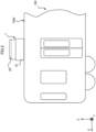
- the power conversion apparatus 1 is installed on a roof 100a of a vehicle 100.
- the power conversion apparatus 1 is mounted on the top end in the vertical direction of the roof 100a while the vehicle 100 is horizontally oriented.
- the X axis indicates the traveling direction of the vehicle 100. In other words, the vehicle 100 runs toward the positive side in the X-axis direction or the negative side in the X-axis direction.
- the Y axis indicates the width direction of the vehicle 100, in other words, the lengthwise direction of railroad ties.
- the Z axis is orthogonal to each of the X and Y axes. The Z axis indicates the vertical direction while the vehicle 100 is horizontally oriented.
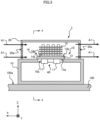
- the power conversion apparatus 1 is installed on the roof 100a of the vehicle 100 and includes a housing 10 to accommodate electronic components 11, which is described below, a cooling device 12 , which is described below, mounted on the housing 10, and a cover 20 disposed over the cooling device 12.
- the electronic components 11 indicate the switching elements 33a to 33f and any heat emitter, such as diode or thyristor, included in the power converter 32 in FIG. 1 .
- the housing 10 accommodates the electronic components 11 and has an opening 10a on the top in the vertical direction.
- the opening 10a is closed by a heat-receiving block 13 of the cooling device 12, which is described below.
- the closing of the opening 10a by the heat-receiving block 13 suppresses the ambient air, water, dust, and other contaminants entering the housing 10.
- the housing 10 has the opening 10a penetrating through the housing 10 in the Z-axis direction while the vehicle 100 is horizontally oriented.
- the housing 10 is preferably attached on the roof 100a such that the housing 10 can be attached to and detached from the roof 100a in the vertical direction while the vehicle 100 is horizontally oriented. Since the housing 10 is attachable and detachable in the vertical direction, detachment of the housing 10 from the roof 100a for maintenance of the power conversion apparatus 1 does not require detachment of electronic equipment surrounding the power conversion apparatus 1, and can thus be readily completed. Also, attachment of the housing 10 to the roof 100a does not require detachment of the electronic equipment surrounding the power conversion apparatus 1, and can thus be readily completed.
- the electronic components 11 are mounted on a first main surface 13a of the heat-receiving block 13 included in the cooling device 12.
- the electronic components 11 emit heat in response to energization and transfer the heat to the heat-receiving block 13, as is described in detail below.
- the cooling device 12 includes the heat-receiving block 13 provided with the electronic components 11, and one or more heat pipes 14 that are partially fixed at the heat-receiving block 13 and extend in a direction away from the heat-receiving block 13. Each of the heat pipes 14 accommodates refrigerant.
- the cooling device 12 is preferably further provided with one or more fins 15 fixed on the outer surfaces of the heat pipes 14. In Embodiment 1, the cooling device 12 includes the heat-receiving block 13, the one or more heat pipes 14, and the one or more fins 15.
- the cooling device 12 and the electronic components 11 mounted on the heat-receiving block 13 of the cooling device 12 are included in a unit 40, which is preferably attached to the housing 10 such that the unit 40 can be attached to and detached from the housing 10 in the vertical direction while the vehicle 100 is horizontally oriented.
- the unit 40 includes the heat-receiving block 13, the one or more heat pipes 14, the one or more fins 15, and the electronic components 11 mounted on the heat-receiving block 13. Since the unit 40 is attachable and detachable in the vertical direction, detachment of the unit 40 from the housing 10 for maintenance of the unit 40 does not require detachment of the electronic equipment surrounding the power conversion apparatus 1, and can thus be readily completed. Also, attachment of the unit 40 to the housing 10 does not require detachment of the electronic equipment surrounding the power conversion apparatus 1, and can thus be readily completed.
- the top end in the vertical direction of the cooling device 12 is preferably located higher than the top end in the vertical direction of the electronic equipment surrounding the power conversion apparatus 1 while the vehicle 100 is horizontally oriented. This arrangement, in which the top end in the vertical direction of the cooling device 12 is higher than the top end in the vertical direction of the surrounding electronic equipment, can improve the cooling efficiency of the power conversion apparatus 1.
- the individual components of the cooling device 12 having the above-described configuration are described below focusing on an exemplary cooling device 12 including eight heat pipes 14.
- the heat-receiving block 13 has the first main surface 13a and a second main surface 13b that face the opposite sides in the Z-axis direction.
- the electronic components 11 are attached to the first main surface 13a.
- the heat pipes 14 are attached to the second main surface 13b. In detail, the heat pipes 14 are inserted and fixed in grooves formed on the second main surface 13b.
- the heat-receiving block 13 is attached to the housing 10 and thus closes the opening 10a.
- the heat-receiving block 13 is made of a material having a high thermal conductivity, for example, a metal, such as copper or aluminum.
- the heat pipes 14 are inserted in the respective grooves on the second main surface 13b of the heat-receiving block 13 and thus fixed at the heat-receiving block 13.
- the heat pipes 14 transfer heat received from the electronic components 11 via the heat-receiving block 13 to traveling wind A1, which is described below, generated as the vehicle 100 travels.
- the heat pipes 14 have a sufficiently high thermal conductivity of, for example, 5,000 W/mK.
- Each of the heat pipes 14 rapidly transfers heat received from one end fixed at the heat-receiving block 13 to the other end and is therefore capable of efficient transfer of heat to the ambient air.
- Each heat pipe 14 has a header portion 14a and a plurality of branch portions 14b in communication with the header portion 14a.
- the heat pipe 14 has a single header portion 14a and four branch portions 14b.
- the header portion 14a is inserted in each groove on the second main surface 13b of the heat-receiving block 13, and fixed at the heat-receiving block 13 by any fixing procedure, such as bonding with an adhesive or soldering.
- the header portion 14a is fixed at the heat-receiving block 13 while being partially exposed from the heat-receiving block 13.
- the header portion 14a is made of a material having a high thermal conductivity, for example, a metal, such as copper or aluminum.
- the branch portions 14b are fixed at the header portion 14a by a procedure, such as welding or soldering, and are in communication with the header portion 14a.
- the branch portions 14b extend in a direction away from the heat-receiving block 13, in detail, a direction away from the second main surface 13b. In Embodiment 1, the branch portions 14b extend in the Z-axis direction.
- the branch portions 14b are made of a material having a high thermal conductivity, for example, a metal, such as copper or aluminum.
- Each of the heat pipes 14 accommodates refrigerant.
- the refrigerant is in a gas-liquid two-phase state at an ordinary temperature.
- the refrigerant is made of a substance, such as water, evaporated when receiving heat from the electronic components 11, and condensed into liquid when discharging heat to the air around the cooling device 12 via the heat pipes 14 and the fins 15, which are described below.
- each of the fins 15 has through holes and fixed at the branch portions 14b while the branch portions 14b extend through the respective through holes.
- the fins 15 are made of a material having a high thermal conductivity, for example, a metal, such as copper or aluminum.
- the fins 15 are made of flat-plate members, arranged with spaces therebetween in the Z-axis direction, and fixed at the branch portions 14b.
- the cover 20 is attached to the housing 10 and disposed over the cooling device 12.
- the cover 20 has any number of vents 20a having any shape on the two surfaces intersecting the traveling direction of the vehicle 100.
- the two surfaces of the cover 20 orthogonal to the X axis has the vents 20a that penetrate through the cover 20 in the X-axis direction.
- a mechanism for cooling the electronic components 11 in the power conversion apparatus 1 having the above-described configuration is described below.
- the heat is transferred from the electronic components 11 via the heat-receiving block 13 and each of the header portions 14a to refrigerant.
- the transferred heat raises the temperature of the refrigerant and evaporates a part of the refrigerant.
- the evaporated refrigerant flows from the header portions 14a into the branch portions 14b via their proximal ends, and travels inside the branch portions 14b toward their distal ends. In other words, the evaporated refrigerant travels inside the heat pipes 14 toward the positive side in the Z-axis direction.
- the traveling wind A1 generated as the vehicle 100 travels flows into the cover 20 via the vents 20a on one surface of the cover 20.
- the traveling wind A1 toward the negative side in the X-axis direction is generated and enters the cover 20 via the vents 20a formed on one surface of the cover 20, as illustrated in FIG. 3 .
- the traveling wind A1 that has entered the cover 20 flows toward the negative side in the X-axis direction while coming into contact with the cooling device 12, in detail, the branch portions 14b and the fins 15.
- the traveling wind A1 then exits the cover 20 via the vents 20a formed on the other surface of the cover 20.
- the heat is transferred from the refrigerant via the branch portions 14b and the fins 15 to the traveling wind A1.
- the heat discharge from the refrigerant lowers the temperature of the refrigerant.
- the refrigerant is accordingly condensed into liquid.
- the refrigerant in the liquid state flows toward the proximal ends of the branch portions 14b and returns to the header portion 14a.
- the refrigerant in the liquid state flows inside the branch portions 14b toward the negative side in the Z-axis direction and returns to the header portion 14a.
- the refrigerant that has condensed and returned to the header portion 14a receives the heat from the electronic components 11 via the heat-receiving block 13, the refrigerant is evaporated again, flows into the branch portions 14b, and then travels toward the distal ends of the branch portions 14b, in other words, travels toward the positive side in the Z-axis direction.
- the refrigerant thus repeats the above-described evaporation and condensation and thereby circulates, so that the heat emitted from the electronic components 11 is discharged to the traveling wind A1, resulting in cooling of the electronic components 11.
- the refrigerant that has not been evaporated that is, the refrigerant in the liquid state has internal temperature differences and generates convection.
- the convection allows the refrigerant to diffuse and transfer the heat from the electronic components 11 in the X-axis direction, leading to efficient cooling of the electronic components 11.
- the above-described circulation and convection of the refrigerant can achieve cooling of the electronic components 11.
- the branch portions 14b are preferably extended as long as possible within the vehicle gauge.
- the vehicle gauge means the maximum dimensions of the vehicle 100 in the section orthogonal to the traveling direction of the vehicle 100, that is, in the YZ plane. In other words, the vehicle 100 and the components installed in the vehicle 100 are located within the vehicle gauge in the YZ plane.
- the vehicle gauge in the Z-axis direction may vary depending on the position in the Y-axis direction.
- the vehicle gauge in the Z-axis direction corresponds to the maximum dimension of the vehicle 100 in the Z-axis direction in the YZ plane.
- the maximum height of the vehicle 100 at the center in the Y-axis direction is higher than the maximum height of the vehicle 100 at the ends in the Y-axis direction.
- the top ends in the vertical direction of the branch portions 14b at the center in the Y-axis direction are located higher than the top ends in the vertical direction of the branch portions 14b at the ends in the Y-axis direction, while the vehicle 100 is horizontally oriented. This configuration allows the branch portions 14b to be extended as long as possible within the vehicle gauge, thereby improving the cooling efficiency of the power conversion apparatus 1.
- the fins 15 are preferably expanded as large as possible within the vehicle gauge.
- the vehicle gauge in the Y-axis direction may vary depending on the position in the Z-axis direction.
- the vehicle gauge in the Y-axis direction corresponds to the maximum dimension of the vehicle 100 in the Y-axis direction in the YZ plane.
- the vehicle gauge in the Y-axis direction has a narrower width at a higher position in the Z-axis direction.
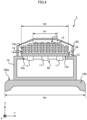
- a length W1 in the Y-axis direction of the fin 15 disposed at a higher position in the vertical direction is shorter than a length W2 in the Y-axis direction of the fin 15 disposed at a lower position in the vertical direction.
- This configuration allows the fins 15 to be expanded as large as possible within the vehicle gauge, thereby improving the cooling efficiency of the power conversion apparatus 1.
- the cover 20 preferably has a shape along the vehicle gauge.
- the traveling wind A1 receives heat from the heat pipes 14 and the fins 15 as described above, the traveling wind A1 at a downstream site has a higher temperature than that at an upstream site.
- the heat pipe 14 at a posterior site in the traveling direction of the vehicle 100 has lower cooling efficiency than that of the heat pipe 14 at an anterior site in the traveling direction of the vehicle 100.
- This phenomenon may cause temperature differences in the electronic components 11 depending on their positions relative to the heat-receiving block 13.
- the header portions 14a therefore preferably extend in the flowing direction of the traveling wind A1, that is, in the X-axis direction. Because of the header portions 14a extending in the X-axis direction, convection of the refrigerant in the liquid state diffuses and transfers heat from the electronic components 11 in the X-axis direction and thus reduces the temperature differences in the electronic components 11.
- the main surfaces of the individual fins 15 preferably extend in the flowing direction of the traveling wind A1, that is, in the X-axis direction.
- the traveling wind A1 that has been introduced via the vents 20a can smoothly flow along the fins 15, leading to improvement of the cooling efficiency of the power conversion apparatus 1.
- the main surfaces of the individual fins 15 extend in the X-axis direction, and the fins 15 are horizontally arranged while the vehicle 100 is horizontally oriented.
- the ratio of the length in the Y-axis direction of at least any one of the fins 15 to a vehicle width W3, which is described below, of the vehicle 100 is preferably equal to or higher than a threshold value.
- the threshold value is determined depending on the cooling capacity required in the cooling device 12, and is 0.5, for example.
- the ratio of the length W2 in the Y-axis direction of the fin 15 at a lower position in the vertical direction to the vehicle width W3 of the vehicle 100 is equal to or higher than 0.5, as illustrated in FIG. 4 .
- the fin 15 Since the ratio of the length in the Y-axis direction of the fin 15 to the vehicle width W3 of the vehicle 100 is defined to be equal to or higher than the threshold value, the fin 15 is allowed to have a larger size than that of a fin included in a cooling device mounted on a side surface of an existing power conversion apparatus installed under the floor of a railway vehicle.
- the fin 15 having a larger size can achieve more efficient heat transfer to the traveling wind A1.
- the power conversion apparatus 1 therefore has higher cooling efficiency than those of existing power conversion apparatuses.
- the length in the X-axis direction of the fin 15 can be reduced by extending the length in the Y-axis direction of the fin 15.
- a reduction in the length of the fin 15 in the X-axis direction, that is, in the flowing direction of the traveling wind A1 leads to a decrease in the pressure loss, so that a larger amount of the traveling wind A1 is allowed to flow between the fins 15.
- This configuration can accordingly improve the cooling efficiency of the power conversion apparatus 1 including the fin 15 having the main surface area identical to that of an existing fin.
- the power conversion apparatus 1 is installed on the roof 100a of the vehicle 100, and includes the heat pipes 14 extending in a direction away from the heat-receiving block 13 that closes the opening 10a on the top in the vertical direction of the housing 10, and the fins 15 fixed at the heat pipes 14.
- the installation of the heat pipes 14 and the fins 15 on the roof 100a of the vehicle 100 can achieve efficient transfer of heat generated in the electronic components 11 to the traveling wind A1. This configuration can therefore improve the cooling capacity of the power conversion apparatus 1.
- the powered vehicles include high-output motors. That is, a power conversion apparatus to feed electric power to each motor also has a higher output and thus emits a larger amount of heat.
- the power conversion apparatus is cooled by forcible wind supply from a blower.
- the electronic components 11 of the power conversion apparatus 1 can be cooled using the traveling wind A1 without a component, such as fan or blower, even in a centralized train system.
- the power conversion apparatus 1 may also be installed at a place other than the top end in the vertical direction of the roof 100a of the vehicle 100.
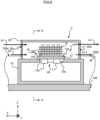
- the description of Embodiment 2 is directed to an exemplary power conversion apparatus 1 installed in an accommodator 100b formed on the roof 100a of the vehicle 100.
- the power conversion apparatus 1 and the accommodator 100b to accommodate the power conversion apparatus 1 are described below focusing on an exemplary accommodator 100b integrated with the roof 100a.
- the roof 100a of the vehicle 100 is provided with the accommodator 100b, which is a recess having a top opening in the vertical direction.
- the top surface in the vertical direction of the accommodator 100b is open while the vehicle 100 is horizontally oriented.
- the accommodator 100b accommodates the housing 10 of the power conversion apparatus 1.
- the bottom of the housing 10 is fixed on the bottom of the accommodator 100b.
- the components of the power conversion apparatus 1 and the mechanism for cooling the electronic components 11 are identical to those in Embodiment 1.
- the structure of the power conversion apparatus 1 for cooling the electronic components 11 using the traveling wind A1 is described in detail below.
- the top end in the vertical direction of at least any one of the heat pipes 14 is located higher than the top end in the vertical direction of the roof 100a while the vehicle 100 is horizontally oriented. As illustrated in FIGS. 6 and 7 , the top ends in the vertical direction of the individual heat pipes 14 are located higher than the top end in the vertical direction of the roof 100a in Embodiment 2.
- the traveling wind A1 can thus come into contact with these heat pipes 14 regardless of the installation of the power conversion apparatus 1 in the accommodator 100b, and can thereby cool the electronic components 11.
- any one of the fins 15 is located higher than the top end in the vertical direction of the roof 100a while the vehicle 100 is horizontally oriented. As illustrated in FIGS. 6 and 7 , the individual fins 15 are located higher than the top end in the vertical direction of the roof 100a in Embodiment 2.
- the traveling wind A1 can thus come into contact with these fins 15 regardless of the installation of the power conversion apparatus 1 in the accommodator 100b, and can thereby cool the electronic components 11.
- the power conversion apparatus 1 according to Embodiment 2 is installed in the accommodator 100b formed on the roof 100a of the vehicle 100 but still can cool the electronic components 11.
- the accommodator 100b on the roof 100a can allow the power conversion apparatus 1 to be installed on the roof 100a and cool the electronic components 11.
- Embodiment 3 is directed to a power conversion apparatus including wind guiding members 21 in order to introduce the traveling wind A1 more effectively into the cover 20.
- the power conversion apparatus 1 includes the wind guiding members 21 disposed adj acent to the respective outer surfaces of the housing 10 intersecting the traveling direction of the vehicle 100, that is, the X-axis direction.
- the wind guiding members 21 guide the traveling wind A1 to the cooling device 12.
- the wind guiding members 21 guide the traveling wind A1 to flow via the vents 20a on the cover 20 to the heat pipes 14 and the fins 15.
- two wind guiding members 21 are arranged in the X-axis direction on both sides of the housing 10.
- the wind guiding members 21 each have a shape of a tube having a through hole extending in the X-axis direction and lacking a part of the side surface.
- FIG. 9 is a sectional view taken along the line C-C of FIG. 8 .
- the wind guiding member 21 has a shape of a square tube lacking one of the side surfaces.
- the wind guiding member 21 is mounted on the roof 100a such that the missing side surface of the tube faces the roof 100a.
- the missing side surface of the tubular wind guiding member 21 is mounted on the bottom of the accommodator 100b formed on the roof 100a.
- the wind guiding members 21 mounted on the roof 100a as described above define an air passage 21a against the roof 100a to guide the traveling wind A1 to the cooling device 12.
- the wind guiding members 21 define the air passage 21a extending in the X-axis direction in order to guide the traveling wind A1 via the vents 20a on the cover 20 to the heat pipes 14 and the fins 15.
- the end face of the air passage 21a defined by the wind guiding members 21 adj acent to the housing 10 preferably has a smaller area than that of the end face of the air passage 21a distant from the housing 10. This configuration can efficiently guide the traveling wind A1 flowing along the roof 100a, to the heat pipes 14 and the fins 15.
- the power conversion apparatus 1 according to Embodiment 3 is provided with the wind guiding members 21 and can thereby efficiently guide the traveling wind A1 to the cooling device 12.
- the two wind guiding members 21 arranged in the X-axis direction on both sides of the housing 10 can efficiently guide the traveling wind A1 to the cooling device 12 in both cases of the vehicle 100 running toward the positive side in the X-axis direction and the vehicle 100 running toward the negative side in the X-axis direction.
- the power conversion apparatus 1 may include two wind guiding members 21 arranged in the X-axis direction on both sides of the housing 10.
- the wind guiding members 21 may be mounted on the top end in the vertical direction of the roof 100a while the vehicle 100 is horizontally oriented.
- the electric power fed to the power conversion apparatus 1 is not necessarily DC power.
- the power conversion apparatus 1 may also be a converter to convert AC power into DC power.
- the electric power fed from the power conversion apparatus 1 to the load is not necessarily three-phase AC power.
- the power conversion apparatus 1 may also feed DC power to the load, which is a DC motor.
- the motor M1 is not necessarily the three-phase induction motor and may also be a synchronous motor or DC motor, for example.
- the power conversion apparatus 1 is not necessarily the self-cooled power conversion apparatus to feed electric power to the motor M1.
- Another example of the load to be fed with electric power from the power conversion apparatus 1 is any electric equipment, such as lighting equipment or air conditioner, which consumes electric power.
- the power conversion apparatus 1 may be installed on not only the railway vehicle but also any moving body, such as trolleybus or tram, which accompanies the traveling wind A1.
- the housing 10 may have any shape provided that the housing 10 can accommodate the electronic components 11 therein and can be installed on the roof 100a.
- the top surface in the vertical direction of the housing 10 may be inclined from the horizontal plane while the vehicle 100 is horizontally oriented.
- the housing 10 preferably has the top surface declining toward the front side in the traveling direction of the vehicle. This configuration can more efficiently bring the traveling wind A1 into contact with the heat pipes 14 and the fins 15.
- the heat-receiving block 13 may be made of a single plate member or a combination of multiple plate members.
- the heat-receiving block 13 made of a single plate member can simplify the process of fabricating the power conversion apparatus 1 and increase the air tightness of the housing 10.
- the heat pipes 14 may have any shape provided that circulation of the refrigerant accommodated in the heat pipes 14 can cool the electronic components 11.
- a power conversion apparatus 2 illustrated in FIG. 10 includes heat pipes 22 bent into an L-shape. A part of each of the heat pipes 22 extends in the X-axis direction and another part extends in the Z-axis direction.
- the power conversion apparatus 2 may also be installed in the accommodator 100b formed on the roof 100a, as in Embodiment 2.
- the heat pipe 14 may have a U-shape or ring shape.
- the section of the heat pipe 14 orthogonal to its extending direction does not necessarily have a circular shape and may also have a flattened shape.
- the section of each of the header portion 14a and the branch portion 14b orthogonal to each extending direction may have a circular or flattened shape.
- the flattened shape indicates a shape formed by narrowing the width of a part of the circular shape than the original width and encompasses elliptical, streamline, and elongated circular shapes.
- the elongated circular shape indicates a shape defined by two circles having the same diameter and the straight lines connecting the contours of the circles with each other.
- each of the heat pipes 14 may be in communication with the respective grooves formed in the heat-receiving block 13.
- each of the heat pipes 14 have a shape of a tube with a closed end.
- the number of heat pipes 14 described above is a mere example and may be arbitrarily varied. Furthermore, the number of header portions 14a and the number of branch portions 14b fixed at each of the header portions 14a described above are mere examples and may be arbitrarily varied.
- the positions of the top ends in the vertical direction of the heat pipes 14 may be mutually different as in the above-described embodiments or identical to each other.
- the number of fins 15 described above is a mere example and may be arbitrarily varied.
- the lengths in the Y-axis direction of the fins 15 may be mutually different as in the above-described embodiments or identical to each other.
- the shape of the fins 15 described above is a mere example and may be arbitrarily modified.
- the fin 15 may be made of a flat-plate member as in the above-described embodiments or a bent-plate member.
- the fins 15 each of which is made of a single plate member are arranged in the Z-axis direction.
- the shape of the fins 15 described above is a mere example and the fins 15 may each be made of multiple plate members.
- the cooling device 12 included in a power conversion apparatus 3 includes multiple fins 23.
- Each of the fins 23 is made of flat-plate members 23a and 23b.
- the fins 15 may be made of the identical member, or at least any one of the fins 15 may be made of a member different from that of the other fins 15. In the case where at least any one of the fins 15 is made of a member different from that of the other fins 15, at least any one of the fins 15 has a thermal conductivity different from that of the other fins 15. In this case, the fin 15 at an upper position in the vertical direction preferably has a higher thermal conductivity than that of the fin 15 at a lower position in the vertical direction.
- the fin 15 at an upper position in the vertical direction may be made of copper while the fin 15 at a lower position in the vertical direction may be made of aluminum.
- the fin 15 at an upper position in the vertical direction can readily come into contact with the traveling wind A1 regardless of other equipment around the power conversion apparatus 1. That is, the cooling efficiency of the power conversion apparatus 1 can be improved by increasing the thermal conductivity of the fin 15 at the upper position in the vertical direction.
- the cover 20 may have any shape provided that the cover 20 is disposed over the cooling device 12 and can introduce the traveling wind A1 into the cover 20.
- the cover 20 may have a curved top surface in the vertical direction.
- the cover 20 may have a flat top surface in the vertical direction.
- the cover 20 preferably has a shape that maximizes the internal space within the vehicle gauge.
- the wind guiding members 21 do not necessarily have a shape of a square tube lacking one of the side surfaces and may also have any shape provided that the wind members 21 can guide the traveling wind A1 to the cooling device 12.
- the wind guiding members 21 may have a hollow cylindrical shape lacking a part of the side surface.
- the wind guiding member 21 may have a shape of a tube the side surfaces of which are partially fixed on the roof 100a and which has a polygonal section.
- the wind guiding members 21 may be disposed apart from the housing 10 and the cover 20 as illustrated in the embodiments, or may be disposed in contact with at least either of the housing 10 and the cover 20.
- wind guiding members 21 may be provided.
- a single wind guiding member 21 may be provided on the front of the vehicle in the traveling direction.
- the switching elements 33a to 33f may include a wide bandgap semiconductor.
- the wide bandgap semiconductor contains a silicon carbide, gallium nitride martial, or diamond, for example.
- the plane of the opening of the accommodator 100b may be in parallel to the horizontal plane while the vehicle 100 is horizontally oriented as in Embodiment 2, or inclined from the horizontal plane while the vehicle 100 is horizontally oriented.
- the accommodator 100b may be independent from the roof 100a.
- the accommodator 100b may be replaced with a pair of on-roof covers 100c that face each other in the width direction.
- the main surfaces of the on-roof covers 100c face each other in the width direction.
- the on-roof covers 100c may each be a plate member having a flat main surface or a plate member having a curved main surface.
- Each of the power conversion apparatuses 1 to 3 may further include a sealing member that surrounds the opening 10a and is in contact with the housing 10 and the heat-receiving block 13.
- the sealing member can improve the air tightness of the housing 10.
Landscapes
- Engineering & Computer Science (AREA)
- Microelectronics & Electronic Packaging (AREA)
- Physics & Mathematics (AREA)
- Thermal Sciences (AREA)
- Power Engineering (AREA)
- Cooling Or The Like Of Electrical Apparatus (AREA)
- Inverter Devices (AREA)
- Electric Propulsion And Braking For Vehicles (AREA)
Applications Claiming Priority (1)
| Application Number | Priority Date | Filing Date | Title |
|---|---|---|---|
| PCT/JP2020/014762 WO2021199252A1 (ja) | 2020-03-31 | 2020-03-31 | 電力変換装置 |
Publications (3)
| Publication Number | Publication Date |
|---|---|
| EP4131767A1 true EP4131767A1 (de) | 2023-02-08 |
| EP4131767A4 EP4131767A4 (de) | 2023-05-31 |
| EP4131767B1 EP4131767B1 (de) | 2026-02-25 |
Family
ID=77928225
Family Applications (1)
| Application Number | Title | Priority Date | Filing Date |
|---|---|---|---|
| EP20929607.8A Active EP4131767B1 (de) | 2020-03-31 | 2020-03-31 | Stromumwandlungsvorrichtung |
Country Status (5)
| Country | Link |
|---|---|
| US (1) | US12250796B2 (de) |
| EP (1) | EP4131767B1 (de) |
| JP (1) | JP7134376B2 (de) |
| CN (1) | CN218788733U (de) |
| WO (1) | WO2021199252A1 (de) |
Families Citing this family (5)
| Publication number | Priority date | Publication date | Assignee | Title |
|---|---|---|---|---|
| JP7408031B2 (ja) * | 2021-10-29 | 2024-01-04 | 三菱電機株式会社 | 電子機器 |
| WO2023144914A1 (ja) * | 2022-01-26 | 2023-08-03 | 三菱電機株式会社 | 電子機器 |
| WO2023199445A1 (ja) * | 2022-04-13 | 2023-10-19 | 三菱電機株式会社 | 電子機器 |
| JP7750454B1 (ja) * | 2024-09-19 | 2025-10-07 | 三菱電機株式会社 | 駆動装置 |
| WO2026062917A1 (ja) * | 2024-09-19 | 2026-03-26 | 三菱電機株式会社 | 駆動装置 |
Family Cites Families (8)
| Publication number | Priority date | Publication date | Assignee | Title |
|---|---|---|---|---|
| JPH07142655A (ja) * | 1993-11-12 | 1995-06-02 | Fuji Electric Co Ltd | ヒートパイプ冷却体 |
| JP2003079164A (ja) | 2001-08-31 | 2003-03-14 | Toshiba Transport Eng Inc | 電力変換装置 |
| JP4098534B2 (ja) * | 2002-02-28 | 2008-06-11 | 三菱電機株式会社 | 移動体用冷却装置 |
| US20100000804A1 (en) * | 2008-07-02 | 2010-01-07 | Ming-Hsiang Yeh | Solar vehicle |
| JP4929325B2 (ja) | 2009-08-27 | 2012-05-09 | 株式会社日立製作所 | 電力変換装置 |
| JP5581119B2 (ja) | 2010-06-07 | 2014-08-27 | 株式会社日立製作所 | 冷却装置,電力変換装置,鉄道車両 |
| JP6753686B2 (ja) * | 2015-08-21 | 2020-09-09 | 株式会社東芝 | 電力変換装置及び鉄道車両 |
| JP6888468B2 (ja) * | 2017-08-01 | 2021-06-16 | 富士電機株式会社 | 鉄道車両用電力変換装置 |
-
2020
- 2020-03-31 EP EP20929607.8A patent/EP4131767B1/de active Active
- 2020-03-31 JP JP2022512973A patent/JP7134376B2/ja active Active
- 2020-03-31 WO PCT/JP2020/014762 patent/WO2021199252A1/ja not_active Ceased
- 2020-03-31 CN CN202090001127.4U patent/CN218788733U/zh active Active
- 2020-03-31 US US17/800,036 patent/US12250796B2/en active Active
Also Published As
| Publication number | Publication date |
|---|---|
| US20230073236A1 (en) | 2023-03-09 |
| CN218788733U (zh) | 2023-04-04 |
| WO2021199252A1 (ja) | 2021-10-07 |
| EP4131767B1 (de) | 2026-02-25 |
| EP4131767A4 (de) | 2023-05-31 |
| JPWO2021199252A1 (de) | 2021-10-07 |
| JP7134376B2 (ja) | 2022-09-09 |
| US12250796B2 (en) | 2025-03-11 |
Similar Documents
| Publication | Publication Date | Title |
|---|---|---|
| US12250796B2 (en) | Power conversion device | |
| US8879259B2 (en) | Cooling system for onboard electrical power converter, and electrical power converter for railway vehicle | |
| US10847441B2 (en) | Cooling system | |
| KR101609934B1 (ko) | 전력 변환 장치 및 이것을 탑재한 철도 차량 | |
| CN100517921C (zh) | 带有整流器的车用交流发电机 | |
| US10453770B2 (en) | Power converter and power converter for railroad vehicle | |
| JP2011259536A (ja) | 冷却装置,電力変換装置,鉄道車両 | |
| US20230182593A1 (en) | EV Charging Connector and EV Charging Station | |
| JP2012070525A (ja) | 車両用の電源装置 | |
| WO2018051403A1 (ja) | 車両用変圧器 | |
| US8107241B2 (en) | Electric power conversion apparatus including cooling units | |
| JPH11251499A (ja) | 電力変換装置 | |
| CN219677015U (zh) | 高效散热的油浸变压器 | |
| JP7408017B2 (ja) | 電子機器 | |
| JP2010284033A (ja) | 鉄道車両の電源装置 | |
| GB2523625A (en) | Power conversion device and railway vehicle equipped with the same | |
| JP2004229500A (ja) | 車両用電力変換装置 | |
| JP2003274671A (ja) | 車両用電力変換装置 | |
| US20250040103A1 (en) | Electronic device | |
| JP7199574B2 (ja) | 冷却装置および電力変換装置 | |
| JP2013154758A (ja) | 車両用制御装置 | |
| JP7408031B2 (ja) | 電子機器 | |
| US20260122858A1 (en) | Electronic apparatus | |
| JP2791270B2 (ja) | 半導体冷却器 | |
| CN217336240U (zh) | 一种散热结构及包括该散热结构的单包逆变器 |
Legal Events
| Date | Code | Title | Description |
|---|---|---|---|
| STAA | Information on the status of an ep patent application or granted ep patent |
Free format text: STATUS: THE INTERNATIONAL PUBLICATION HAS BEEN MADE |
|
| PUAI | Public reference made under article 153(3) epc to a published international application that has entered the european phase |
Free format text: ORIGINAL CODE: 0009012 |
|
| STAA | Information on the status of an ep patent application or granted ep patent |
Free format text: STATUS: REQUEST FOR EXAMINATION WAS MADE |
|
| 17P | Request for examination filed |
Effective date: 20220801 |
|
| AK | Designated contracting states |
Kind code of ref document: A1 Designated state(s): AL AT BE BG CH CY CZ DE DK EE ES FI FR GB GR HR HU IE IS IT LI LT LU LV MC MK MT NL NO PL PT RO RS SE SI SK SM TR |
|
| A4 | Supplementary search report drawn up and despatched |
Effective date: 20230426 |
|
| RIC1 | Information provided on ipc code assigned before grant |
Ipc: H02M 7/5387 20070101ALI20230421BHEP Ipc: H02M 7/00 20060101ALI20230421BHEP Ipc: H05K 7/20 20060101ALI20230421BHEP Ipc: H02M 7/48 20070101AFI20230421BHEP |
|
| DAV | Request for validation of the european patent (deleted) | ||
| DAX | Request for extension of the european patent (deleted) | ||
| RIC1 | Information provided on ipc code assigned before grant |
Ipc: H02M 7/48 20070101AFI20250813BHEP Ipc: H05K 7/20 20060101ALI20250813BHEP Ipc: H02M 7/00 20060101ALI20250813BHEP Ipc: H02M 7/5387 20070101ALI20250813BHEP |
|
| GRAP | Despatch of communication of intention to grant a patent |
Free format text: ORIGINAL CODE: EPIDOSNIGR1 |
|
| STAA | Information on the status of an ep patent application or granted ep patent |
Free format text: STATUS: GRANT OF PATENT IS INTENDED |
|
| INTG | Intention to grant announced |
Effective date: 20250924 |
|
| GRAS | Grant fee paid |
Free format text: ORIGINAL CODE: EPIDOSNIGR3 |
|
| GRAA | (expected) grant |
Free format text: ORIGINAL CODE: 0009210 |
|
| STAA | Information on the status of an ep patent application or granted ep patent |
Free format text: STATUS: THE PATENT HAS BEEN GRANTED |
|
| AK | Designated contracting states |
Kind code of ref document: B1 Designated state(s): AL AT BE BG CH CY CZ DE DK EE ES FI FR GB GR HR HU IE IS IT LI LT LU LV MC MK MT NL NO PL PT RO RS SE SI SK SM TR |
|
| REG | Reference to a national code |
Ref country code: CH Ref legal event code: F10 Free format text: ST27 STATUS EVENT CODE: U-0-0-F10-F00 (AS PROVIDED BY THE NATIONAL OFFICE) Effective date: 20260225 Ref country code: GB Ref legal event code: FG4D |
|
| REG | Reference to a national code |
Ref country code: DE Ref legal event code: R096 Ref document number: 602020067766 Country of ref document: DE |
|
| REG | Reference to a national code |
Ref country code: IE Ref legal event code: FG4D |
|
| PGFP | Annual fee paid to national office [announced via postgrant information from national office to epo] |
Ref country code: DE Payment date: 20260320 Year of fee payment: 7 |
|
| PGFP | Annual fee paid to national office [announced via postgrant information from national office to epo] |
Ref country code: FR Payment date: 20260323 Year of fee payment: 7 |