EP4131849A1 - Élément de circuit, composant pse et procédé de surveillance et de protection d'un réseau podl - Google Patents
Élément de circuit, composant pse et procédé de surveillance et de protection d'un réseau podl Download PDFInfo
- Publication number
- EP4131849A1 EP4131849A1 EP22182937.7A EP22182937A EP4131849A1 EP 4131849 A1 EP4131849 A1 EP 4131849A1 EP 22182937 A EP22182937 A EP 22182937A EP 4131849 A1 EP4131849 A1 EP 4131849A1
- Authority
- EP
- European Patent Office
- Prior art keywords
- voltage
- switching element
- network
- pse
- component
- Prior art date
- Legal status (The legal status is an assumption and is not a legal conclusion. Google has not performed a legal analysis and makes no representation as to the accuracy of the status listed.)
- Granted
Links
Images


Classifications
-
- H—ELECTRICITY
- H04—ELECTRIC COMMUNICATION TECHNIQUE
- H04L—TRANSMISSION OF DIGITAL INFORMATION, e.g. TELEGRAPHIC COMMUNICATION
- H04L12/00—Data switching networks
- H04L12/02—Details
- H04L12/10—Current supply arrangements
-
- G—PHYSICS
- G01—MEASURING; TESTING
- G01R—MEASURING ELECTRIC VARIABLES; MEASURING MAGNETIC VARIABLES
- G01R19/00—Arrangements for measuring currents or voltages or for indicating presence or sign thereof
- G01R19/165—Indicating that current or voltage is either above or below a predetermined value or within or outside a predetermined range of values
- G01R19/16504—Indicating that current or voltage is either above or below a predetermined value or within or outside a predetermined range of values characterised by the components employed
- G01R19/16519—Indicating that current or voltage is either above or below a predetermined value or within or outside a predetermined range of values characterised by the components employed using FET's
-
- G—PHYSICS
- G05—CONTROLLING; REGULATING
- G05F—SYSTEMS FOR REGULATING ELECTRIC OR MAGNETIC VARIABLES
- G05F1/00—Automatic systems in which deviations of an electric quantity from one or more predetermined values are detected at the output of the system and fed back to a device within the system to restore the detected quantity to its predetermined value or values, i.e. retroactive systems
- G05F1/10—Regulating voltage or current
- G05F1/46—Regulating voltage or current wherein the variable actually regulated by the final control device is DC
-
- H—ELECTRICITY
- H04—ELECTRIC COMMUNICATION TECHNIQUE
- H04L—TRANSMISSION OF DIGITAL INFORMATION, e.g. TELEGRAPHIC COMMUNICATION
- H04L12/00—Data switching networks
- H04L12/28—Data switching networks characterised by path configuration, e.g. LAN [Local Area Networks] or WAN [Wide Area Networks]
- H04L12/40—Bus networks
- H04L2012/4026—Bus for use in automation systems
-
- H—ELECTRICITY
- H04—ELECTRIC COMMUNICATION TECHNIQUE
- H04L—TRANSMISSION OF DIGITAL INFORMATION, e.g. TELEGRAPHIC COMMUNICATION
- H04L43/00—Arrangements for monitoring or testing data switching networks
- H04L43/50—Testing arrangements
Definitions
- the present invention relates to a switching element according to the preamble of claim 1, a PSE component according to the preamble of claim 6 and a method for monitoring and protecting a PoDL network according to the preamble of claim 8.
- Safety devices for fieldbus applications are known in the prior art and are functionally used for safe power limitation to protect people.
- the DE 10 2020 113 822 A1 discloses an output fuse in which the output switching elements do not have to be switched off cyclically for testing, since they are located in a permanently active control loop which monitors their functionality, the gate voltages being measured, among other things.
- This interconnection is only designed for bus technologies in which the data line is separated from the supply lines.
- PoDL Power over Data Line
- SPE Single Pair Ethernet
- PoDL data-carrying supply lines
- an electronic interconnection element of a PSE component for a PoDL network or network section comprising a voltage connection and/or voltage source, a first line for connecting a pole of the voltage connection to a first connection of a physical layer (PHY), a second line for connecting the second pole of the voltage connection to the second connection of the physical layer (PHY), at least one switching element in each of the lines, the switching elements being connected to at least one control unit comprising a microprocessor and can be controlled as a result, and at least one voltage measuring unit is provided, by means of which the voltage drop can be detected as a measured value across each switching element and can be fed to the microprocessor.
- the wiring provides that current and voltage are (at least) redundantly measured, calculated and compared in order to determine the power.
- the current measurement takes place (at least also) by measuring the gate voltages of at least two FETs (field effect transistors).
- an improved embodiment of the interconnection element consists in the two switching elements having a voltage as a manipulated variable in the conducting state, which is related to the conducting current, which are connected to the control unit in a data-conducting manner.
- At least one switching element is advantageously a field effect transistor (FET), in particular a normally closed (nc) field effect transistor.
- FET field effect transistor
- nc normally closed field effect transistor
- the switching elements can also be in the form of MOSFETs or IGBTs.
- the switching elements are structurally and functionally identical, ie are of identical or essentially identical design.
- the PSE component can be further improved in that the physical layer (PHY) has two connections, each of the connections being directly upstream of an interconnection of passive components, in particular at least one resistor and at least one capacitor.
- PHY physical layer
- the circuit element includes a PHY, a PSE component and a coupling with passive components.
- the coupling towards the PHY must be designed to be safety-related.
- the failure of a component must not lead to power being injected via this path. This can be done as suggested in IEEE 802.3cg:2019 to achieve intrinsic safety.
- the critical components are connected in duplicate, one after the other or next to each other, depending on their function.
- the invention includes a method for monitoring and protecting a PoDL network and/or network section, wherein at least one switching element is provided in two lines connected to a voltage source and the voltage drop across each switching element is measured, depending on the IST -Voltage measured values (controlled variable) the switching elements are controlled by means of a voltage (manipulated variable) which is related to the current flow (disturbance variable).
- the current flow is technically independently measured in both lines and the measured values and/or data derived from them are evaluated together in a processor unit by determining the current flow in each switching element using the control voltage and comparing the current flow of the two switching elements for monitoring.
- the current flow in each switching element is advantageously measured using the drive voltage (U_GS, gate voltage) the current flow disturbance variable, I-S), which means calculated from the drive voltages (U_GS, gate voltage). This determination takes place in both switching elements in parallel and independently.
- the network or network sections are monitored by means of the current flows (flow rates) generated and compared in this way and, based on this, any necessary process control, warning messages and/or shutdowns are initiated.
- the method therefore provides for the switching elements, such as the FET, to be located in a control loop.
- the flow current is determined using the control voltage (U_GS, gate voltage) and the flow current of the two switching elements is compared and monitored. If an inequality in the flow current is determined, both switching elements are switched off because the inequality indicates a fault that is either in the switching element itself or in an external potential coupled in.
- the redundantly measured flow rate is evaluated and compared with a specification such as an FET characteristic curve.
- a specification such as an FET characteristic curve.
- the current is not actively limited, but rather monitored and switched off if it is exceeded.
- the PHY transmission power is not separately measured, monitored or limited, but the actual supply and/or the voltage source itself is switched off completely.
- a transmission power of the PHY advantageously remains as an autonomous signal even after a shutdown, the transmission power of which is less than 0.5 watts.
- a further improved variant of the method provides that a SET characteristic curve is stored for each switching element and the resistance value and/or the gate voltage (U_GS) of the two switching elements changes within defined limits and the ACTUAL Value is compared with the TARGET characteristic and / or corridor of the TARGET characteristic of the respective switching element.
- the resistance value and/or the respective gate voltage (U_GS) can be changed individually or synchronously.
- a further, improved variant of the method provides that after a shutdown due to the detection of an unequal current intensity and/or an unequal current flow, a user intervention takes place before switching on again, in particular after an error analysis and/or error correction by a user or a specification by the controller , by specifying an output limitation or a power limitation, a renewed switch-on and/or normal operation takes place due to internal specifications of the controller.
- a PSE component is used in the method, which is designed according to one of the above embodiments and is operated accordingly.
- the method described here in the various embodiments can be used in particular for a supply and data network in which the data transmission and the power line take place together via a two-wire cable, in particular a single pair Ethernet (SPE) and/or twisted pair Ethernet (TPE) .
- SPE single pair Ethernet
- TPE twisted pair Ethernet
- the limitation of the current can be that the current is switched off completely to 0 A or to a defined value>0, in particular to a value of up to 100 mA.
- the advantage of not switching off completely is that data transmission can be continued with the low current flow, for example in order to be able to transmit status data or forward control commands.
- the particular advantage is that the same FETs are used as the output switching elements for current measurement, which are also used for switching off, so that no additional components are installed in the power path must.
- This connection also enables safe power limitation and shutdown of an electronic component or device that itself does not have a safety function, such as a frequency converter.
- Complex, functionally safe bus communication can be dispensed with with the interconnection according to the invention, since the power limitation and, if necessary, shutdown take place at a higher level.
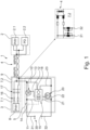
- the PoDL network or network section 1 shown is structured as regularly provided for in IEEE 802.3cg:2019. It includes a physical layer 8 (PHY) for communication of the data on both sides of the SPE link 4, namely on the side of the PSE 3 (Power Sourcing Equipment) and on the other side of the SPE link, the PD 2 (Powered Device ).
- PSE Power Sourcing Equipment
- the embodiment according to the invention relates to the PSE 3 side, so that the PD 2 is not explained in any more detail and comprises the (micro)electronic parts and components familiar to the person skilled in the art.
- the PSE 3 essentially includes a protective circuit 9 from the PHY 8 and the passive components 7.1, 7.2 and a switching element 5.
- the protective circuit 9 includes the passive components 7.1 and 7.2 for coupling the PHY and PSE.
- passive components 7.1, 7.2 are necessary for the coupling.
- the passive component 7.1 must be designed to be safety-related.
- the transmission power of the PHY 8 is the lowest power level.
- the recognition of the PD 2 via a detection voltage and the transmission of the power classes via SCCP (Serial Communication Classification Protocol) correspond to the usual standards.
- a passive component 7.1 is provided in the protective circuit 9, which has a series-connected resistor 16 and a capacitor 17 comprises.
- the structure of the second, passive component 7.2 is enlarged in the lower detailed view and shown with the individual components.
- the interconnection element 5 includes a voltage connection 30 (positive position) with a first line 31, which leads to the first connection 8.1 of a physical layer (PHY) 8.
- the second line 32 connects the other voltage connection 30 (negative pole) to the second connection 8.2 of the PHY 8 of the PSE 3.
- Both lines 31, 32 each include a switching element 10, 20 designed as an FET.
- the voltage connection 30 can lead to an external source , as in figure 1 indicated or formed into an integrated source such as a battery, as in figure 2 shown.
- a central control unit 15 picks up the voltage (U_DS) across the respective switching element 10, 20 (FET) via the pair of lines 11, 13 in the first line 31 and via the pair of lines 21, 23 in the second line 32.
- each switching element 10, 20 is controlled and regulated via a respectively associated control line 12, 22, which is connected to the control unit 15.
- the control unit 15, which for example has a circuit board as the base support, also includes a microprocessor 6 for at least part of the data processing and a voltmeter 18. Other, customary further (micro)electronic elements of the control unit 15 are not shown.
- the regulation takes place electronically via operational amplifiers, but can also take place via the microprocessor.
- the microprocessor is used for control and monitoring purposes.
- the functionally safe shutdown according to the invention relates only to the PSE 3.
- the power can only be limited to the maximum transmission power of the PHY 8.
- Ethernet can optionally be used as a black channel for a safe protocol. It is thus possible to operate a safe protocol (e.g. PROFIsafe or CIPP Safety). Both a secure protocol and a standard protocol can be operated.
- a safe protocol e.g. PROFIsafe or CIPP Safety
- Both a secure protocol and a standard protocol can be operated.
- the advantage of the invention consists in the fact that the higher-level safe shutdown is possible even without a safe protocol.
- an additional ammeter 14 is also shown as an optional extension, which is also connected to the control unit 15 via a data line with a dot-dash line.
- the current flow thus measured in the positive pole line 31 can be compared with the currents determined from the voltages and used for monitoring.
- this additional, separate current measurement can be further improved if an additional ammeter 14.1, 14.2 is provided in both lines 31, 32 and the currents determined in this way are compared and used for monitoring.
- the switching elements are in the switched-on state in a control loop 24 in which the voltage 34 (U_DS) is kept constant as a controlled variable.
- This voltage 34 is tapped off via the lines 11, 13 in the line 31 and via the lines 21, 23 in the line 32, as in FIGS figures 1 and 2 shown.
- the (gate) voltage 35 (U_GS) applied via the control lines 12, 22 is in a typical ratio to the disturbance variable 33 (I_S) of the flowing current. This relationship can be taken from a component-specific characteristic curve for each actuating element 10, 12, as in the lower graph in FIG figure 3 was presented.
- the output voltage 19 can optionally be read back via the lines 13 in the first line 31 (plus pole) and the second line 32 (minus pole) via the line 23 and also (redundantly) measured be what was previously referred to as "behind" the switching elements 10,20.
- the switching elements 10, 20 can be measured in an analogous manner via the pair of lines 11, 21.
- the PHY 8 is limited to the transmission power. This does not require the performance or the measure current accurately.
- the current measurement essentially serves to monitor the switching elements 10, 20 designed as FETs. Thus, in this variant, only two safe power stages are normally provided.
- a safety-related measurement of the current and the voltage can be carried out, from which the power can be calculated. This is compared with a specification, such as the performance classes according to IEEE 802.3cg:2019 according to the table above. For this purpose, the specification must always be securely configured. Any Skinny Client Control Protocol (SCCP) present has a control effect. If the specification is not met, a safe shutdown is initiated.
- SCCP Skinny Client Control Protocol
Landscapes
- Engineering & Computer Science (AREA)
- Computer Networks & Wireless Communication (AREA)
- Signal Processing (AREA)
- Physics & Mathematics (AREA)
- General Physics & Mathematics (AREA)
- Power Sources (AREA)
- Arrangements For Transmission Of Measured Signals (AREA)
- Electronic Switches (AREA)
Applications Claiming Priority (1)
| Application Number | Priority Date | Filing Date | Title |
|---|---|---|---|
| DE102021119955.7A DE102021119955A1 (de) | 2021-08-02 | 2021-08-02 | Verschaltungselement, PSE-Bauteil und Verfahren zur Überwachung und Schutz eines PoDL-Netzes |
Publications (2)
| Publication Number | Publication Date |
|---|---|
| EP4131849A1 true EP4131849A1 (fr) | 2023-02-08 |
| EP4131849B1 EP4131849B1 (fr) | 2026-01-28 |
Family
ID=82547454
Family Applications (1)
| Application Number | Title | Priority Date | Filing Date |
|---|---|---|---|
| EP22182937.7A Active EP4131849B1 (fr) | 2021-08-02 | 2022-07-05 | Élément de circuit, composant pse et procédé de surveillance et de protection d'un réseau podl |
Country Status (4)
| Country | Link |
|---|---|
| US (1) | US12155493B2 (fr) |
| EP (1) | EP4131849B1 (fr) |
| CN (1) | CN115701694A (fr) |
| DE (1) | DE102021119955A1 (fr) |
Families Citing this family (2)
| Publication number | Priority date | Publication date | Assignee | Title |
|---|---|---|---|---|
| DE102024123660A1 (de) * | 2024-08-19 | 2026-03-05 | Samson Aktiengesellschaft | Stellgerätevorrichtung, Verfahren und elektronische Überwachungseinrichtung zum Überwachen eines betriebsgemäßen Zusammenhanges zwischen einem Auslösesignal und einem Überprüfungssignal |
| DE102024123659A1 (de) * | 2024-08-19 | 2026-02-19 | Samson Aktiengesellschaft | Stellgerätevorrichtung, Verfahren und elektronische Überwachungseinrichtung zum Überwachen eines betriebsgemäßen Zusammenhanges zwischen einem Auslösen einer Schaltfunktion und einem Überprüfungssignal |
Citations (4)
| Publication number | Priority date | Publication date | Assignee | Title |
|---|---|---|---|---|
| US7702302B1 (en) | 2005-12-12 | 2010-04-20 | Linear Technology Corporation | Combination of high-side and low-side current control in system for providing power over communication link |
| DE102015105702B3 (de) * | 2015-04-14 | 2016-08-04 | Beckhoff Automation Gmbh | Bussystem mit einem Einspeisemodul und einem Verbrauchermodul |
| US20190312751A1 (en) | 2018-04-05 | 2019-10-10 | Cisco Technology, Inc. | Wire fault and electrical imbalance detection for power over communications cabling |
| DE102020113822A1 (de) | 2019-06-13 | 2020-12-17 | Turck Holding Gmbh | Vorrichtung und Verfahren zur elektrischen Stromkreisüberwachung |
Family Cites Families (15)
| Publication number | Priority date | Publication date | Assignee | Title |
|---|---|---|---|---|
| US5694109A (en) * | 1996-09-04 | 1997-12-02 | International Controls And Measurement Corp. | Two-wire dc communication system and transceiver |
| US20080198635A1 (en) * | 2007-02-21 | 2008-08-21 | Broadcom Corporation | Pulse width modulated ground/return for powered device |
| US10673717B1 (en) * | 2013-11-18 | 2020-06-02 | Amazon Technologies, Inc. | Monitoring networked devices |
| US9859951B2 (en) * | 2013-11-26 | 2018-01-02 | Linear Technology Corporation | Power over data lines detection and classification scheme |
| US9967104B2 (en) * | 2014-11-19 | 2018-05-08 | Linear Technology Corporation | Detecting ground isolation fault in ethernet PoDL system |
| US9923727B2 (en) * | 2015-07-09 | 2018-03-20 | Microsemi Corporation | Standby powering for power over Ethernet |
| EP3176978B1 (fr) * | 2015-12-01 | 2018-06-20 | Linear Technology Corporation | Architectures de circuit pour la protection contre les défaillances de câble podl |
| KR102525573B1 (ko) * | 2016-03-17 | 2023-04-24 | 현대자동차주식회사 | 파워 오버 데이터 라인 시스템의 전력 제어 방법 |
| US11165252B2 (en) * | 2016-12-29 | 2021-11-02 | Commscope Technologies Llc | Method and apparatus for automatic detection and selection of power over ethernet and power over powered data lines |
| US11005670B2 (en) | 2018-06-15 | 2021-05-11 | Phihong Technology Co., Ltd. | Low standby power circuit architecture for power saving within power source equipment |
| US11281282B2 (en) * | 2018-11-19 | 2022-03-22 | Genetec Inc. | Intermediary device for extracting power supplied over a data connection |
| US11075438B2 (en) * | 2018-11-20 | 2021-07-27 | WaveMark, Inc. | Radiofrequency identification equipped medical cabinet systems and methods of assembly and use thereof |
| US20210109294A1 (en) * | 2019-10-10 | 2021-04-15 | Xieon Networks S.A.R.L. | Illuminating receptacle and method |
| US11582048B2 (en) * | 2020-07-17 | 2023-02-14 | Cisco Technology, Inc. | Bi-directional power over ethernet for digital building applications |
| US11599493B2 (en) * | 2021-07-28 | 2023-03-07 | Logitech Europe S.A. | Multi-host USB hub and docking system |
-
2021
- 2021-08-02 DE DE102021119955.7A patent/DE102021119955A1/de active Pending
-
2022
- 2022-06-30 CN CN202210756565.7A patent/CN115701694A/zh active Pending
- 2022-07-05 EP EP22182937.7A patent/EP4131849B1/fr active Active
- 2022-08-01 US US17/816,532 patent/US12155493B2/en active Active
Patent Citations (4)
| Publication number | Priority date | Publication date | Assignee | Title |
|---|---|---|---|---|
| US7702302B1 (en) | 2005-12-12 | 2010-04-20 | Linear Technology Corporation | Combination of high-side and low-side current control in system for providing power over communication link |
| DE102015105702B3 (de) * | 2015-04-14 | 2016-08-04 | Beckhoff Automation Gmbh | Bussystem mit einem Einspeisemodul und einem Verbrauchermodul |
| US20190312751A1 (en) | 2018-04-05 | 2019-10-10 | Cisco Technology, Inc. | Wire fault and electrical imbalance detection for power over communications cabling |
| DE102020113822A1 (de) | 2019-06-13 | 2020-12-17 | Turck Holding Gmbh | Vorrichtung und Verfahren zur elektrischen Stromkreisüberwachung |
Also Published As
| Publication number | Publication date |
|---|---|
| EP4131849B1 (fr) | 2026-01-28 |
| CN115701694A (zh) | 2023-02-10 |
| DE102021119955A1 (de) | 2023-02-02 |
| US12155493B2 (en) | 2024-11-26 |
| US20230042972A1 (en) | 2023-02-09 |
Similar Documents
| Publication | Publication Date | Title |
|---|---|---|
| DE102012212123B4 (de) | Vorrichtung zur Diagnose einer Schaltungsanordnung | |
| DE102014107561B4 (de) | Strommessung und Überstromerkennung | |
| EP2887081B1 (fr) | Dispositif destiné à la surveillance d'isolation | |
| DE19500452B4 (de) | Verfahren und Vorrichtung zur Überwachung der Funktionsfähigkeit eines Leerlaufstellers | |
| DE102013219141A1 (de) | Interlock-Schaltkreis zur Absicherung eines elektrischen Bordnetzes | |
| EP4131849B1 (fr) | Élément de circuit, composant pse et procédé de surveillance et de protection d'un réseau podl | |
| DE102012101987A1 (de) | Spannungsregler für einen Gleitstrommotor | |
| EP2182605A1 (fr) | Agencement de commutation pour la protection de dispositifs électroniques contre des tensions logiques erronées | |
| EP3641087A1 (fr) | Agencement de circuit électrique et procédé d'accouplement d'un appareil de surveillance de l'isolation à un système d'alimentation électrique non mis à la terre | |
| WO2004017080A1 (fr) | Procede pour surveiller au moins deux soupapes electromagnetiques d'un moteur a combustion interne faisant partie notamment d'un vehicule automobile | |
| EP3583004B1 (fr) | Circuit destiné à mettre en uvre une comparaison | |
| EP0413938A1 (fr) | Circuit pour surveiller l'état de commutation d'un transistor de puissance | |
| DE102007022210B3 (de) | Mehrstufiges Verbindersystem für medizinische Verwendung | |
| WO2018001665A1 (fr) | Dispositif de commande multi-tension pour véhicule automobile, véhicule automobile et procédé de fonctionnement du dispositif de commande | |
| WO2012116967A1 (fr) | Module de batterie et batterie avec détection redondante de la tension des éléments | |
| DE102023200456A1 (de) | Verfahren zum Überwachen einer Energieversorgung eines Kraftfahrzeugs | |
| WO2020233937A1 (fr) | Dispositif et procédé de commande de courant d'un actionneur | |
| EP3314764A1 (fr) | Borne réversible électronique d'un disjoncteur de protection | |
| EP2130275A1 (fr) | Détection d'erreur dans un appareil de commande | |
| DE10261454B4 (de) | Motorsteuerung mit sicherem Halt | |
| EP3669145A1 (fr) | Appareil de commande pourvu d'un commutateur et procédé de protection contre les courts-circuits de câbles de masse et capteurs | |
| DE102021119739A1 (de) | Überwachungsbaugruppe sowie System mit einer Überwachungsbaugruppe | |
| DE10261450A1 (de) | Elektromotor mit integrierter elektronischer Steuereinrichtung | |
| DE102024206339B3 (de) | Schaltungsvorrichtung, Stromrichter, elektrischer Achsantrieb, Kraftfahrzeug und Verfahren zum Betreiben einer Schaltungsvorrichtung | |
| EP4046276B1 (fr) | Système et procédé d'identification de commutateurs à semi-conducteur sans commutation |
Legal Events
| Date | Code | Title | Description |
|---|---|---|---|
| PUAI | Public reference made under article 153(3) epc to a published international application that has entered the european phase |
Free format text: ORIGINAL CODE: 0009012 |
|
| STAA | Information on the status of an ep patent application or granted ep patent |
Free format text: STATUS: THE APPLICATION HAS BEEN PUBLISHED |
|
| AK | Designated contracting states |
Kind code of ref document: A1 Designated state(s): AL AT BE BG CH CY CZ DE DK EE ES FI FR GB GR HR HU IE IS IT LI LT LU LV MC MK MT NL NO PL PT RO RS SE SI SK SM TR |
|
| STAA | Information on the status of an ep patent application or granted ep patent |
Free format text: STATUS: REQUEST FOR EXAMINATION WAS MADE |
|
| 17P | Request for examination filed |
Effective date: 20230731 |
|
| RBV | Designated contracting states (corrected) |
Designated state(s): AL AT BE BG CH CY CZ DE DK EE ES FI FR GB GR HR HU IE IS IT LI LT LU LV MC MK MT NL NO PL PT RO RS SE SI SK SM TR |
|
| STAA | Information on the status of an ep patent application or granted ep patent |
Free format text: STATUS: EXAMINATION IS IN PROGRESS |
|
| 17Q | First examination report despatched |
Effective date: 20250224 |
|
| REG | Reference to a national code |
Ref legal event code: R079 Free format text: PREVIOUS MAIN CLASS: H04L0012100000 Ipc: G05F0001460000 Ref country code: DE Ref legal event code: R079 Ref document number: 502022006861 Country of ref document: DE Free format text: PREVIOUS MAIN CLASS: H04L0012100000 Ipc: G05F0001460000 |
|
| GRAP | Despatch of communication of intention to grant a patent |
Free format text: ORIGINAL CODE: EPIDOSNIGR1 |
|
| STAA | Information on the status of an ep patent application or granted ep patent |
Free format text: STATUS: GRANT OF PATENT IS INTENDED |
|
| RIC1 | Information provided on ipc code assigned before grant |
Ipc: G05F 1/46 20060101AFI20250930BHEP Ipc: H04L 12/10 20060101ALI20250930BHEP Ipc: H04L 12/40 20060101ALI20250930BHEP |
|
| INTG | Intention to grant announced |
Effective date: 20251014 |
|
| GRAS | Grant fee paid |
Free format text: ORIGINAL CODE: EPIDOSNIGR3 |
|
| GRAA | (expected) grant |
Free format text: ORIGINAL CODE: 0009210 |
|
| STAA | Information on the status of an ep patent application or granted ep patent |
Free format text: STATUS: THE PATENT HAS BEEN GRANTED |
|
| P01 | Opt-out of the competence of the unified patent court (upc) registered |
Free format text: CASE NUMBER: UPC_APP_0017671_4131849/2025 Effective date: 20251215 |
|
| AK | Designated contracting states |
Kind code of ref document: B1 Designated state(s): AL AT BE BG CH CY CZ DE DK EE ES FI FR GB GR HR HU IE IS IT LI LT LU LV MC MK MT NL NO PL PT RO RS SE SI SK SM TR |
|
| REG | Reference to a national code |
Ref country code: CH Ref legal event code: F10 Free format text: ST27 STATUS EVENT CODE: U-0-0-F10-F00 (AS PROVIDED BY THE NATIONAL OFFICE) Effective date: 20260128 Ref country code: GB Ref legal event code: FG4D Free format text: NOT ENGLISH |
|
| REG | Reference to a national code |
Ref country code: DE Ref legal event code: R096 Ref document number: 502022006861 Country of ref document: DE |
|
| REG | Reference to a national code |
Ref country code: IE Ref legal event code: FG4D Free format text: LANGUAGE OF EP DOCUMENT: GERMAN |