EP4131905A1 - Ensemble carte de circuit imprimé souple et dispositif électronique - Google Patents
Ensemble carte de circuit imprimé souple et dispositif électronique Download PDFInfo
- Publication number
- EP4131905A1 EP4131905A1 EP22741140.2A EP22741140A EP4131905A1 EP 4131905 A1 EP4131905 A1 EP 4131905A1 EP 22741140 A EP22741140 A EP 22741140A EP 4131905 A1 EP4131905 A1 EP 4131905A1
- Authority
- EP
- European Patent Office
- Prior art keywords
- printed circuit
- flexible printed
- transmission member
- fpc
- reels
- Prior art date
- Legal status (The legal status is an assumption and is not a legal conclusion. Google has not performed a legal analysis and makes no representation as to the accuracy of the status listed.)
- Granted
Links
Images






Classifications
-
- H—ELECTRICITY
- H05—ELECTRIC TECHNIQUES NOT OTHERWISE PROVIDED FOR
- H05K—PRINTED CIRCUITS; CASINGS OR CONSTRUCTIONAL DETAILS OF ELECTRIC APPARATUS; MANUFACTURE OF ASSEMBLAGES OF ELECTRICAL COMPONENTS
- H05K5/00—Casings, cabinets or drawers for electric apparatus
- H05K5/02—Details
- H05K5/0217—Mechanical details of casings
- H05K5/0226—Hinges
-
- H—ELECTRICITY
- H04—ELECTRIC COMMUNICATION TECHNIQUE
- H04M—TELEPHONIC COMMUNICATION
- H04M1/00—Substation equipment, e.g. for use by subscribers
- H04M1/02—Constructional features of telephone sets
- H04M1/0202—Portable telephone sets, e.g. cordless phones, mobile phones or bar type handsets
- H04M1/026—Details of the structure or mounting of specific components
- H04M1/0277—Details of the structure or mounting of specific components for a printed circuit board assembly
-
- H—ELECTRICITY
- H04—ELECTRIC COMMUNICATION TECHNIQUE
- H04M—TELEPHONIC COMMUNICATION
- H04M1/00—Substation equipment, e.g. for use by subscribers
- H04M1/02—Constructional features of telephone sets
- H04M1/0202—Portable telephone sets, e.g. cordless phones, mobile phones or bar type handsets
- H04M1/0206—Portable telephones comprising a plurality of mechanically joined movable body parts, e.g. hinged housings
- H04M1/0208—Portable telephones comprising a plurality of mechanically joined movable body parts, e.g. hinged housings characterized by the relative motions of the body parts
-
- H—ELECTRICITY
- H04—ELECTRIC COMMUNICATION TECHNIQUE
- H04N—PICTORIAL COMMUNICATION, e.g. TELEVISION
- H04N23/00—Cameras or camera modules comprising electronic image sensors; Control thereof
- H04N23/57—Mechanical or electrical details of cameras or camera modules specially adapted for being embedded in other devices
-
- H—ELECTRICITY
- H05—ELECTRIC TECHNIQUES NOT OTHERWISE PROVIDED FOR
- H05K—PRINTED CIRCUITS; CASINGS OR CONSTRUCTIONAL DETAILS OF ELECTRIC APPARATUS; MANUFACTURE OF ASSEMBLAGES OF ELECTRICAL COMPONENTS
- H05K1/00—Printed circuits
- H05K1/02—Details
- H05K1/0277—Bendability or stretchability details
- H05K1/028—Bending or folding regions of flexible printed circuits
-
- H—ELECTRICITY
- H05—ELECTRIC TECHNIQUES NOT OTHERWISE PROVIDED FOR
- H05K—PRINTED CIRCUITS; CASINGS OR CONSTRUCTIONAL DETAILS OF ELECTRIC APPARATUS; MANUFACTURE OF ASSEMBLAGES OF ELECTRICAL COMPONENTS
- H05K1/00—Printed circuits
- H05K1/02—Details
- H05K1/14—Structural association of two or more printed circuits
- H05K1/148—Arrangements of two or more hingeably connected rigid printed circuit boards, i.e. connected by flexible means
-
- H—ELECTRICITY
- H04—ELECTRIC COMMUNICATION TECHNIQUE
- H04M—TELEPHONIC COMMUNICATION
- H04M1/00—Substation equipment, e.g. for use by subscribers
- H04M1/02—Constructional features of telephone sets
- H04M1/0202—Portable telephone sets, e.g. cordless phones, mobile phones or bar type handsets
- H04M1/0206—Portable telephones comprising a plurality of mechanically joined movable body parts, e.g. hinged housings
- H04M1/0208—Portable telephones comprising a plurality of mechanically joined movable body parts, e.g. hinged housings characterized by the relative motions of the body parts
- H04M1/0214—Foldable telephones, i.e. with body parts pivoting to an open position around an axis parallel to the plane they define in closed position
- H04M1/0216—Foldable in one direction, i.e. using a one degree of freedom hinge
-
- H—ELECTRICITY
- H05—ELECTRIC TECHNIQUES NOT OTHERWISE PROVIDED FOR
- H05K—PRINTED CIRCUITS; CASINGS OR CONSTRUCTIONAL DETAILS OF ELECTRIC APPARATUS; MANUFACTURE OF ASSEMBLAGES OF ELECTRICAL COMPONENTS
- H05K2201/00—Indexing scheme relating to printed circuits covered by H05K1/00
- H05K2201/05—Flexible printed circuits [FPCs]
- H05K2201/051—Rolled
-
- H—ELECTRICITY
- H05—ELECTRIC TECHNIQUES NOT OTHERWISE PROVIDED FOR
- H05K—PRINTED CIRCUITS; CASINGS OR CONSTRUCTIONAL DETAILS OF ELECTRIC APPARATUS; MANUFACTURE OF ASSEMBLAGES OF ELECTRICAL COMPONENTS
- H05K2201/00—Indexing scheme relating to printed circuits covered by H05K1/00
- H05K2201/05—Flexible printed circuits [FPCs]
- H05K2201/055—Folded back on itself
-
- H—ELECTRICITY
- H05—ELECTRIC TECHNIQUES NOT OTHERWISE PROVIDED FOR
- H05K—PRINTED CIRCUITS; CASINGS OR CONSTRUCTIONAL DETAILS OF ELECTRIC APPARATUS; MANUFACTURE OF ASSEMBLAGES OF ELECTRICAL COMPONENTS
- H05K2201/00—Indexing scheme relating to printed circuits covered by H05K1/00
- H05K2201/05—Flexible printed circuits [FPCs]
- H05K2201/056—Folded around rigid support or component
-
- H—ELECTRICITY
- H05—ELECTRIC TECHNIQUES NOT OTHERWISE PROVIDED FOR
- H05K—PRINTED CIRCUITS; CASINGS OR CONSTRUCTIONAL DETAILS OF ELECTRIC APPARATUS; MANUFACTURE OF ASSEMBLAGES OF ELECTRICAL COMPONENTS
- H05K2201/00—Indexing scheme relating to printed circuits covered by H05K1/00
- H05K2201/20—Details of printed circuits not provided for in H05K2201/01 - H05K2201/10
- H05K2201/2027—Guiding means, e.g. for guiding flexible circuits
Definitions
- Embodiments of this application relate to the technical field of flexible printed circuits, and in particular, to a flexible printed circuit assembly and an electronic device including the flexible printed circuit assembly.
- a flexible printed circuit Flexible Printed Circuit, FPC
- FPC Flexible Printed Circuit
- a stationary structural member such as a printed circuit board (Printed Circuit Board, PCB).
- PCB printed circuit Board
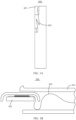
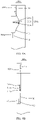
- the FPC 603 is in a straight state when the camera assembly 601 extends, and has a redundant length when the camera assembly 601 retracts.
- the redundant length of the FPC 603 is in a freely-moving state. Therefore, folding shown in FIG. 1A is likely to occur.
- FIG. 1B in a foldable-display structure 500, a side display 501 rotates relative to a stationary member 503, one end of an FPC 505 is fixed at the stationary member 503, and an other end of the FPC moves with the side display 501.
- a shape of a redundant length of the FPC 505 is out of control.
- the redundant length is likely to be squeezed into a half-folded state by a structural member (the stationary member or the side display).
- a structural member the stationary member or the side display.
- this application provides a flexible printed circuit assembly with a controllable redundant length.
- the flexible printed circuit assembly includes a flexible printed circuit and a control structure.
- the control structure includes a transmission member and two reels. The two reels are arranged on the transmission member at an interval. The flexible printed circuit passes between the two reels.
- the transmission member is configured to drive the two reels to rotate, so that the flexible printed circuit is wound on peripheral sides of the two reels.
- a redundant length generated by the flexible printed circuit is converted from a free shape to an arcuate shape formed by bending when driven by the control structure, so that a stress is evenly distributed on the arc of the flexible printed circuit, thereby avoiding stress concentration on the flexible printed circuit, and increasing the life of the flexible printed circuit.
- the two reels have a same diameter and are rotatable symmetrically with respect to a rotary shaft of the transmission member.
- the two reels are arranged symmetrically with respect to the rotary shaft of the transmission member, so that the movement of the flexible printed circuit is stable.
- a length L of each of the reels along an axial direction is greater than a width W of the flexible printed circuit, and a difference between the length L and the width W ranges from 0.8 mm to 1.2 mm.
- the length L of the reel along the axial direction is greater than the width W of the flexible printed circuit, so that the flexible printed circuit can be stably wound on the reel without falling off during the rotation of the reel.
- the flexible printed circuit assembly includes a flexible printed circuit and a control structure.
- the control structure includes a transmission member, a guide shaft, and a connecting member.
- the guide shaft is located on a side of the flexible printed circuit.
- the connecting member has one end arranged on the transmission member and an other end connected to the guide shaft.
- the transmission member is configured to drive the connecting member to drive the guide shaft to move, and the guide shaft is configured to drive the flexible printed circuit to bend.
- the transmission member rotates and drives the connecting member to drive the guide shaft to move, so that the guide shaft drives the flexible printed circuit to bend and form a circular arc shape.
- a stress is evenly distributed on the arc of the flexible printed circuit, thereby avoiding stress concentration on the flexible printed circuit, and increasing the life of the flexible printed circuit.
- a plurality of guide shafts and a plurality of connecting members are arranged, where one end of each connecting member is arranged on the transmission member, and an other end of each connecting member is connected to one of the guide shafts; along an extending direction of the flexible printed circuit, each two adjacent guide shafts are respectively located on two opposite sides of the flexible printed circuit; and the transmission member is configured to drive the plurality of connecting members to drive the corresponding guide shafts to move, and the plurality of guide shafts are configured to drive the flexible printed circuit to bend to form a plurality of arcs, so that the flexible printed circuit is in a wave form.
- the transmission member drives the plurality of connecting members to drive the plurality of guide shafts to move, and the plurality of guide shafts drive the flexible printed circuit to bend to form a plurality of arcs, and bending directions of adjacent two arcs are different, thereby forming a wave form.
- the plurality of guide shafts have a same diameter, and the arcs formed by the bending of the flexible printed circuit are semicircles.
- the diameters of the plurality of guide shafts are the same, but are not limited thereto. Since the diameters of the plurality of guide shafts are the same, and the guide shafts provide guidance for the bending of the flexible printed circuit, radii of the arcs formed by the bending of the flexible printed circuit are the same, and bending variations of the flexible printed circuit are the same.
- this application provides an electronic device.
- the electronic device includes a stationary member, at least one movable member movable relative to the stationary member, and a flexible printed circuit assembly.
- the circuit board assembly includes a flexible printed circuit and a control structure.
- a plurality of connecting portions are arranged on the flexible printed circuit, at least one of the connecting portions is arranged on the movable member, and the control structure is arranged between the two connecting portions.
- the control structure includes a transmission member and two reels. The two reels are arranged on the transmission member at an interval.
- the flexible printed circuit passes between the two reels.
- the transmission member is configured to drive the two reels to rotate, so that the flexible printed circuit is wound on peripheral sides of the two reels.
- control structure includes a transmission member, a guide shaft, and a connecting member.
- the guide shaft is located on a side of the flexible printed circuit.
- the connecting member has one end arranged on the transmission member and an other end connected to the guide shaft.
- the transmission member is configured to drive the connecting member to drive the guide shaft to move, and the guide shaft is configured to drive the flexible printed circuit to bend.
- the flexible printed circuit assembly with a controllable redundant length is applied to the electronic device, so that the electrical connection of the movable member of the electronic device is stable, thereby improving functional stability of the electronic device.
- the movable member is a camera assembly, where the camera assembly is configured to extend and retract relative to the stationary member, and one of the connecting portions of the flexible printed circuit is arranged on the camera assembly.
- the flexible printed circuit assembly with a controllable redundant length is applied to the electronic device, so that the electrical connection of the camera assembly of the electronic device is stable, thereby improving functional stability of the electronic device.
- two movable members a first middle frame and a second middle frame are arranged, where the first middle frame and the second middle frame are rotatably arranged on the stationary member to be folded or unfolded, and two of the connecting portions of the flexible printed circuit are respectively arranged on the first middle frame and the second middle frame.
- the flexible printed circuit assembly with a controllable redundant length is applied to the electronic device, so that the electrical connection of the first middle frame and the second middle frame of the electronic device is stable, thereby improving functional stability of the electronic device.
- the transmission member is drive-connected to the movable member, so that the transmission member rotates and moves.
- the flexible printed circuit assembly includes a flexible printed circuit and a control structure.
- the control structure is configured to drive a redundant length generated by movement of the flexible printed circuit to bend to form an arc.
- the control structure includes a transmission member and two reels. The two reels are arranged on the transmission member at an interval. The flexible printed circuit passes between the two reels along an extending direction.
- the transmission member is configured to drive the two reels to rotate, so that the flexible printed circuit is wound on peripheral sides of the two reels.
- the control structure includes a transmission member, a guide shaft, and a connecting member.
- the guide shaft is located on a side of the flexible printed circuit.
- the connecting member has one end arranged on the transmission member and an other end connected to the guide shaft.
- the transmission member is configured to drive the connecting member to drive the guide shaft to move, and the guide shaft is configured to drive the flexible printed circuit to bend.
- the transmission member of the control structure drives the reels or the guide shaft, and provides guidance for bending of the flexible printed circuit, so that a redundant length of the flexible printed circuit is bent to form an arcuate or circular arc shape. Since the redundant length of the flexible printed circuit is controlled by the control structure, uncertainty of the redundant length is avoided. A stress is evenly distributed on the arc of the flexible printed circuit, thereby avoiding stress concentration, and increasing the life of the flexible printed circuit.
- an embodiment of this application provides a flexible printed circuit assembly 100 with a controllable redundant length.
- the flexible printed circuit assembly 100 is applicable to an electronic device.
- the electronic device includes a stationary member and a movable member movable relative to the stationary member.
- the movable member can extend/retract, slide, rotate, fold, or the like relative to the stationary member.
- the electronic device includes but is not limited to a mobile terminal (such as a mobile phone, a tablet computer, or a notebook computer), a wearable device (such as a watch, glasses, or the like), a display device (such as a television or a display), a camera, or a game console.
- the flexible printed circuit assembly 100 includes a flexible printed circuit (Flexible Printed Circuit, FPC) 10 and a control structure 20.
- a plurality of connecting portions are arranged on the FPC 10.
- the plurality of connecting portions include a first connecting portion 11 and a second connecting portion 12, but this application is not limited thereto.
- the first connecting portion 11 is connected to the movable member, and the second connecting portion 12 is connected to the stationary member, but this application is not limited thereto.
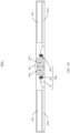
- the first connecting portion 11 moves with the movable member. Therefore, a distance from the second connecting portion 12 increases (shown in FIG. 2B ) or decreases (shown in FIG. 2C ).
- the control structure 20 is arranged between the first connecting portion 11 and the second connecting portion 12.
- the control structure 20 drives the FPC 10 to bend, so that the FPC 10 forms a transitional shape of an arcuate shape. Since the redundant length of the FPC 10 is controlled by the control structure 20, uncertainty of the redundant length is avoided. The redundant length of the FPC 10 is converted from a free shape to an arcuate shape formed by bending when driven by the control structure 20, so that a stress is evenly distributed on the arc of the FPC 10, thereby avoiding stress concentration on the FPC 10, and increasing the life of the FPC 10.
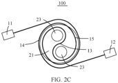
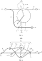
- the control structure 20 includes a transmission member 21 and two reels 23.
- the two reels 23 are arranged on the transmission member 21 at an interval.
- the FPC 10 passes between the two reels 23 along an extending direction, as shown in FIG. 2B .
- the transmission member 21 is configured to drive the two reels 23 to rotate, so that the FPC 10 is wound on entire peripheral sides of the two reels 23, as shown in FIG. 2C .
- the FPC 10 further includes a winding portion 13 between the first connecting portion 11 and the second connecting portion 12 and a first extension 14 and a second extension 15 located on two sides of the winding portion 13.
- the winding portion 13 passes between the two reels 23 and is wound on the two reels 23 in a substantially S shape.
- the transmission member 21 rotates and drives the two reels 23 to rotate.
- the first extension 14 and the second extension 15 of the FPC 10 rotate with the reels 23 and are wound around entire peripheral sides of the first connecting portion 11 and the second connecting portion 12.
- the transmission member 21 rotates while moving relative to the stationary member, so that the first extension 14 and the second extension 15 do not generate redundant lengths and are stressed evenly when released and wound simultaneously.
- the transmission member 21 moves away from the second connecting portion 12 while rotating, to release the first extension 14 and the second extension 15, so that the second extension 15 does not generate a redundant length.
- the transmission member 21 rotates and moves toward the second connecting portion 12, to avoid an excessive pulling force on the second extension 15 during simultaneous wounding of the first extension 14 and the second extension 15, so that winding forces on the first extension 14 and the second extension 15 are even.
- first extension 14 and the second extension 15 have a same length, but this application is not limited thereto.
- the control structure 20 is substantially located at middle symmetrical positions between the first connecting portion 11 and the second connecting portion 12, so that the forces on the first extension 14 and the second extension 15 are more even. It may be understood that, in other embodiments, the first extension 14 and the second extension 15 may have different lengths, provided that a part of the first extension 14 or the second extension 15 is wound on the two reels 23.
- a diameter D of each of the reels 23 satisfies: 1 mm ⁇ D ⁇ 5 mm, but this application is not limited thereto.
- the diameter D of the reel 23 is set according to a requirement for a bending radius of the FPC 10 and a space in the electronic device.
- an axial length L of the reel 23 is greater than a width W of the FPC 10.
- a difference between the length L and the width W ranges from 0.8 mm to 1.2 mm.
- the difference between the length L and the width W is 1 mm.
- the electronic device may include two movable members, and the first connecting portion 11 and the second connecting portion 12 of the FPC 10 are respectively connected to the two movable members.
- the first connecting portion 11 and the second connecting portion 12 can move with the two movable members.
- the control structure 20 is arranged between the first connecting portion 11 and the second connecting portion 12, and a position of the transmission member 21 relative to the stationary member may remain unchanged.
- the transmission member 21 only rotates to cause the first extension 14 and the second extension 15 to be simultaneously wound or released.
- the plurality of connecting portions of the FPC 10 may further include a third connecting portion (not shown).
- the first connecting portion 11, the second connecting portion 12, and the third connecting portion are arranged in sequence.
- the second connecting portion 12 is fixedly arranged in the electronic device, and a position of the second connecting portion relative to the stationary member remains unchanged.
- the first connecting portion 11 and the third connecting portion are connected to the movable member for movement.
- Two control structures 20 are arranged between the first connecting portion 11 and the second connecting portion 12 and between the second connecting portion 12 and a third connecting portion respectively.
- the diameters of the two reels 23 are the same, and distances between the two reels 23 and the rotary shaft of the transmission member 21 are equal, so that the two reels 23 can rotate symmetrically with respect to the rotary shaft of the transmission member 21. Rotation speeds of the first extension 14 and the second extension 15 during winding and releasing are uniform, so that the movement stability of the FPC 10 is improved. It may be understood that, in other embodiments, the diameters of the two reels 23 may be different, and the distances between the two reels 23 and the rotary shaft of the transmission member 21 may be not equal, so that the FPC 10 is wound around the entire peripheral sides of the two reels 23 in a substantially cam shape.
- the reels 23 of the control structure 20 provide guidance for bending of the redundant length of the FPC 10, so as to present a transitional shape of an arc.
- the FPC 10 is configured with a sufficient length, and the first extension 14 and the second extension 15 wound around the peripheral sides of the two reels 23 are in no contact or partially in contact.
- the transmission member 21 may be drive-connected to a movable structure in the electronic device by the transmission structure, so that the transmission member 21 can realize rotation or movement.
- the transmission structure may be a structure that realizes transmission by gear transmission, a sliding block linkage, or the like.
- the transmission member 21 may be connected to a driving structure arranged in the electronic device, and the transmission member 21 is driven by the driving structure to move.
- the rotation speed of the transmission member 21 and the diameters of the reels 23 may be set according to a variation of the distance between the first connecting portion 11 and the second connecting portion 12 and a speed of the movable member.
- an electronic device 400a is a mobile terminal device, such as a foldable-display mobile phone or a foldable-display electronic reader.
- Two movable members a first middle frame 402 and a second middle frame 403 are arranged.
- the first middle frame 402 and the second middle frame 403 are rotatably arranged on the stationary member 401.
- the first middle frame 402 is in a rotation-preventing connection to a first hinge 404 to prevent rotation
- the first hinge 404 is connected to the first middle frame 402 without relative rotation.
- the first hinge 404 is rotatably arranged on the stationary member 401.
- the second middle frame 403 is in a rotation-preventing connection to the second hinge 405, and the second hinge 405 is connected to the second middle frame 403 without relative rotation.
- the second hinge 405 is rotatably arranged on the stationary member 401.
- the FPC 10 passes by the entire peripheral sides of the first hinge 404 and the second hinge 405 along the extending direction, the first connecting portion 11 is arranged on a circuit board 4021 of the first middle frame 402, and the second connecting portion 12 is arranged on a circuit board 4031 of the second middle frame 403, and the FPC 10 realizes electrical connection between the first middle frame 402 and the second middle frame 403.
- the first middle frame 402 and the second middle frame 403 can be rotated relative to the stationary member 401 to form a plane, as shown in FIG.
- the flexible printed circuit assembly 100a includes two control structures, that is, a control structure 20a and a control structure 20b. Two reels 23a of the control structure 20a are wound by the FPC 10 and are located between the first connecting portion 11 and the first hinge 404. Two reels 23b of the control structure 20b are wound by the FPC 10 and are located between the second connecting portion 12 and the second hinge 405.
- the FPC 10 When the first middle frame 402 and the second middle frame 403 are converted from the folded state to the unfolded state by an external driving force, the FPC 10 has redundant lengths on two sides of the stationary member 401.
- a transmission member 21a rotates and moves to drive the two reels 23a to rotate
- a transmission member 21b rotates and moves to drive the two reels 23b to rotate, so that parts of the FPC 10 located on the two sides of the stationary member 401 are wound around the two reels 23a and the two reels 23b respectively.
- the FPC 10 is connected between the first middle frame 402 and the second middle frame 403 in the transitional shape of the arc, and the control structure 20a and the control structure 20b can control the redundant length of the FPC 10, thereby avoiding a folded shape.
- the transmission member 21a rotates and moves to drive the two reels 23a to rotate
- the transmission member 21b rotates and moves to drive the two reels 23b to rotate, so as to release the FPC 10 wound around the reels 23a and the reels 23b.
- the external driving force causes the first hinge 404 to rotate with the first middle frame 402 and the second hinge 405 to rotate with the second middle frame 403.
- the transmission member 21a may be drive-connected to the first hinge 404 (the movable structure in the electronic device) to realize rotation and movement
- the transmission member 21b may be drive-connected to the second hinge 405 (the movable structure in the electronic device) to realize rotation and movement.
- a gear portion 4041 is arranged on the first hinge 404
- the transmission member 21 is a gear structure
- the transmission member 21 is engaged with and drive-connected to the gear portion 4041.
- the transmission member 21 may be caused to rotate and move in other driving manners.
- an independent driving structure such as a motor assembly is arranged in the electronic device 400a, and the motor assembly directly drives the transmission member 21 to move.
- the first middle frame 402 and the second middle frame 403 may be rotatably arranged on the stationary member 401 by one hinge (not shown).
- the hinge includes a shaft and two leaves arranged on the shaft, and the first middle frame 402 and the second middle frame 403 are respectively connected to the two leaves.
- the electronic device 400b is a mobile terminal device such as a mobile phone including a movable member that can perform a telescopic movement.
- a stationary member 401a is a circuit board on a middle frame or a housing structure of the electronic device 400b.
- a movable member is a camera assembly 406.
- the camera assembly 406 is slidably arranged on the stationary member 401a.
- the camera assembly 406 can extend out of or retract into the housing of the electronic device 400b.
- the first connecting portion 11 of the FPC 10 is arranged on the camera assembly 406, and the second connecting portion 12 is arranged on the stationary member 401a.
- Two reels 23c of a control structure 20c are wound by the FPC 10 and are located between the first connecting portion 11 and the second connecting portion 12.
- the distance between the first connecting portion 11 and the second connecting portion 12 of the FPC 10 is shortened, and the transmission member 21c rotates and moves to drive the first extension 14 and the second extension 15 of the FPC 10 to be wound around peripheral sides of the two reels 23c, so that the FPC 10 is connected between the camera assembly 406 and the stationary member 401a in the transitional shape of the arc, and the control structure 20c can control the redundant length of the FPC 10, thereby avoiding a folded shape.
- the electronic device 400b further includes a driving structure (not shown).
- the transmission member 21c may be connected to the driving structure, and the driving structure drives the camera assembly 406 to move and drive the transmission member 21c to rotate and move.
- an embodiment of this application provides a flexible printed circuit assembly 200 with a controllable redundant length.
- the flexible printed circuit assembly 200 is applicable to an electronic device.
- the electronic device includes a stationary member and a movable member movable relative to the stationary member.
- the flexible printed circuit assembly 200 includes an FPC 10 and a control structure 210.
- a plurality of connecting portions are arranged on the FPC 10.
- the plurality of connecting portions include a first connecting portion 11 and a second connecting portion 12, but this application is not limited thereto.
- the first connecting portion 11 is connected to the movable member, and the second connecting portion 12 is connected to the stationary member, but this application is not limited thereto.
- the electronic device may further include another movable member, and the second connecting portion 12 may be connected to the another movable member, so that the first connecting portion 11 and the second connecting portion 12 of the FPC 10 both can move.
- the first connecting portion 11 moves with the movable member. Therefore, a distance from the second connecting portion 12 increases (a position shown by dashed lines in FIG. 5 ) or decreases (a position shown by solid lines in FIG. 5 ).
- the FPC 10 has a redundant length.
- the control structure 210 is arranged between the first connecting portion 11 and the second connecting portion 12.
- the control structure 210 drives the FPC 10 to bend, so that the FPC 10 forms a transitional shape of a circular arc.
- the redundant length of the FPC 10 is limited by the control structure 210, so that a radius R of the arc formed by the bending of the FPC 10 satisfies requirements.
- the radius R is greater than 1 mm.
- the redundant length of the FPC 10 is converted from a free shape to the arc shape formed by bending when driven by the control structure 210, so that a stress is evenly distributed on the arc of the FPC 10, thereby avoiding stress concentration on the FPC 10, and increasing the life of the FPC 10.
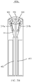
- the control structure 210 includes a transmission member 211, a guide shaft 215, and a connecting member 213.
- One transmission member 211, one guide shaft 215, and one connecting member 213 are arranged, but this application is not limited thereto.
- the transmission member 211 may be drive-connected to a movable structure in the electronic device, so that the transmission member 211 can realize rotation or movement.
- One end of the connecting member 213 is arranged on the transmission member 211, and an other end of the connecting member is arranged on the guide shaft 215.
- the guide shaft 215 is located on a side of the FPC 10.
- the transmission member 211 rotates and drives the connecting member 213 to drive the guide shaft 215 to move.
- the guide shaft 215 moves to come into contact with a side of the FPC 10, and continues moving to drive the FPC 10 to bend to form an arc shape.
- the FPC 10 moves along the guide shaft 215 by a tension of the FPC, and the arcs formed by the FPC 10 on two sides of the guide shaft 215 are substantially the same.
- the redundant length of the FPC 10 is converted from a free shape to the arc shape formed by bending when driven by the control structure 210, so that a stress is evenly distributed on the arc of the FPC 10, thereby avoiding stress concentration on the FPC 10, and increasing the life of the FPC 10.
- the guide shaft 215 is rotatably arranged on the connecting member 213, so that the guide shaft 215 can roll along the FPC 10. In this way, a friction between the guide shaft 215 and the FPC 10 is reduced. It may be understood that, in other embodiments, the guide shaft 215 and the connecting member 213 may be connected together without relative rotation.
- Diameters of the plurality of guide shafts 215 are the same, but this application is not limited thereto. Since the diameters of the plurality of guide shafts 215 are the same, and the guide shafts 215 provide guidance for the bending of the FPC 10, radii of the arcs formed by the bending of the FPC 10 are the same, and bending variations of the FPC 10 are the same.
- the diameters of the guide shafts 215 may be different, and the FPC 10 bends to form a plurality of arcs with different radii.
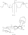
- a control structure 31 of a flexible printed circuit assembly 300 is substantially the same as the control structure 210, except that the control structure 31 includes two connecting members, that is, a connecting member 313a and a connecting member 313b, and two guide shafts, that is, a guide shaft 315a and a guide shaft 315b.
- One end of the connecting member 313a is arranged on the transmission member 311, and an other end of the connecting member is arranged on the guide shaft 315a.
- One end of the connecting member 313b is arranged on the transmission member 311, and an other end of the connecting member is arranged on the guide shaft 315b.
- the guide shaft 315a and the guide shaft 315b are located on two opposite sides of the FPC 10 respectively.
- the first connecting portion 11 and the second connecting portion 12 of the FPC 10 move relative to each other. Therefore, a distance between the two portions increases (a position shown by dashed lines in FIG. 6 ) or decreases (a position shown by solid lines in FIG. 6 ).
- the transmission member 311 drives the connecting member 313a and the connecting member 313b to respectively drive the corresponding guide shaft 315a and the guide shaft 315b to move.
- the guide shaft 315a and the guide shaft 315b respectively move from the two sides of the FPC 10 to come into contact with the FPC 10, and continue moving to cause the FPC 10 to move to form two arcs.
- the two arcs form a wave form.
- three, four, or other numbers of guide shafts 215 and connecting members 213 may be arranged.
- the numbers of the guide shafts 215 and the connecting members 213 may be set according to the redundant length generated by the FPC 10, as long as each two adjacent guide shafts 215 are respectively located on the two opposite sides of the FPC 10 along the extending direction of the FPC 10.
- the transmission member 211 drives the plurality of connecting members 213 to drive the plurality of guide shafts 215 to move, and the plurality of guide shafts 215 drive the FPC 10 to bend to form a plurality of arcs, and bending directions of adjacent two arcs are different, so that the FPC 10 forms a wave form.
- Each transmission member 211 is connected to one connecting member 213, to drive one corresponding guide shaft 215 to come into contact with the FPC 10, so as to cause the FPC 10 to bend to form an arc.
- an electronic device 400c is substantially the same as the electronic device 400a in the first embodiment, except that a control structure of the electronic device 400c is different from the control structures 20a and 20b of the electronic device 400a.
- the control structure of the electronic device 400c is the control structure 210 shown in FIG. 5 .
- the flexible printed circuit assembly 200a in the electronic device 400c includes two control structures, that is, a control structure 210a and a control structure 210b.
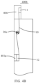
- the control structure 210a is located between the first hinge 404 and the circuit board 4021 of the first middle frame 402.
- the control structure 210b is located between the second hinge 405 and the circuit board 4031 of the second middle frame 403.
- the FPC 10 When the first middle frame 402 and the second middle frame 403 are converted from the folded state to the unfolded state by an external driving force, the FPC 10 has redundant lengths on two sides of the stationary member 401.
- a transmission member 211a of the control structure 210a rotates and moves, so that a connecting member 213a drives a guide shaft 215a to come into contact with the FPC 10, thereby causing the FPC 10 between the first hinge 404 and the circuit board 4021 to bend to form an arc.
- a transmission member 211b of the control structure 210b rotates and moves, so that a connecting member 213b drives a guide shaft 215b to come into contact with the FPC 10, thereby causing the FPC 10 between the second hinge 405 and the circuit board 4031 to bend to form an arc.
- the FPC 10 is connected between the first middle frame 402 and the second middle frame 403 in the transitional shape of the arc, and the control structure 210a and the control structure 210b can control the redundant length of the FPC 10, thereby avoiding a folded shape.
- parts of the FPC 10 between the first hinge 404 and the circuit board 4021 and between the second hinge 405 and the circuit board 4031 substantially each exhibit a plane.
- the transmission member 211a and the transmission member 211b respectively drive the guide shaft 215a and the guide shaft 215b to move to be tangent to the substantially planar portions on the FPC 10, but this application is not limited thereto.
- the guide shaft 215a and the guide shaft 215b may not be in contact with the FPC 10.
- the parts of the FPC 10 between the first hinge 404 and the circuit board 4021 and between the second hinge 405 and the circuit board 4031 each may be a curved surface.
- the guide shaft 215a and the guide shaft 215b respectively intersect with the curved surfaces, and a bending radius of the curved surface is greater than a radius of the arc of the FPC 10 when the electronic device 400c is in the unfolded state.
- R is the radius of the arc formed by the bending of the FPC 10, and R>1 mm. It may be understood that, in other embodiments, the arc generated by the FPC 10 may be an inferior arc, and correspondingly, the distances 1 may be less than 4R.
- the transmission member 211a is drive-connected to the first hinge 404 (the movable structure) to realize rotation and movement
- the transmission member 211b is drive-connected to the second hinge 405 (the movable structure) to realize rotation and movement.
- a gear portion 4041 is arranged on the first hinge 404
- the transmission member 211a is a gear structure
- the transmission member 211a is engaged with and drive-connected to the gear portion 4041.
- One end of the connecting member 213 is connected to the transmission member 211 without relative rotation, and an other end of the connecting member is rotatably connected to the guide shaft 215a.
- the transmission member 211a rotates about an axis of the transmission member and rotates about the rotary shaft of the first hinge 404 to achieve movement, so that the guide shaft 215a comes into contact with the FPC 10 to cause the FPC 10 to bend.
- the electronic device 400c acquires energy of the external driving force by using the movable members (the first middle frame 402, the first hinge 404, the second middle frame 403, and the second hinge 405), and the movement of the movable members drives the transmission member 211a and the transmission member 211b to move, so that the control structure 210a and the control structure 210b can control the redundant length of the FPC 10.
- the movable members the first middle frame 402, the first hinge 404, the second middle frame 403, and the second hinge 405
- an electronic device 400d is substantially the same as the electronic device 400a in the first embodiment, except that a control structure of the electronic device 400d is different from the control structures 20a and 20b of the electronic device 400a.
- a control structure of the electronic device 400d is the same as the control structure 31 shown in FIG. 6 .
- the flexible printed circuit assembly 300 in the electronic device 400d includes two control structures, that is, a control structure 31c and a control structure 31d.
- the control structure 31c is located between the first hinge 404 and the circuit board 4021 of the first middle frame 402.
- the control structure 31d is located between the second hinge 405 and the circuit board 4031 of the second middle frame 403.
- the FPC 10 When the first middle frame 402 and the second middle frame 403 are converted from the folded state to the unfolded state by an external driving force, the FPC 10 has redundant lengths on two sides of the stationary member 401.
- Two guide shafts 315c of the control structure 31c are in contact with the two sides of the FPC 10, and cause the FPC 10 between the first hinge 404 and the circuit board 4021 to bend to form two arcs.
- Two guide shafts 315d of the control structure 31d are in contact with the two sides of the FPC 10, and cause the FPC 10 between the second hinge 405 and the circuit board 4031 to bend to form two arcs.
- the FPC 10 is connected between the first middle frame 402 and the second middle frame 403 in the transitional shape of the arc, and the control structure 31c and the control structure 31d can control the redundant length of the FPC 10, thereby avoiding a folded shape.
- an electronic device 400e is substantially the same as the electronic device 400b in the second embodiment, except that a control structure 210c of the electronic device 400e is different from the control structure 20c of the electronic device 400b.
- the control structure 210c of the electronic device 400e is the same as the control structure 210 shown in FIG. 5 .
- the control structure 210c is located between the first connecting portion 11 and the second connecting portion 12 of the FPC 10.
- the distance between the first connecting portion 11 and the second connecting portion 12 of the FPC 10 is shortened.
- the transmission member 211c rotates and moves, to drive the connecting member 213c to drive the guide shaft 215c to move to come into contact with the FPC 10, and continues moving to cause the FPC 10 bend to form an arc.
- the FPC 10 is connected between the camera assembly 406 and the stationary member 401a in the transitional shape of the arc, and the control structure 210c can control the redundant length of the FPC 10, thereby avoiding a half-folded shape.
- the transmission member of the control structure of the flexible printed circuit assembly drives the reels or the guide shaft to move, and provides guidance for bending of the FPC, so that the redundant length of the FPC is bent to form an arcuate or circular arc shape. Since the redundant length of the FPC is controlled by the control structure, uncertainty of the redundant length is avoided. A stress is evenly distributed on the arc of the FPC, thereby avoiding stress concentration, and increasing the life of the FPC.
Landscapes
- Engineering & Computer Science (AREA)
- Signal Processing (AREA)
- Microelectronics & Electronic Packaging (AREA)
- Multimedia (AREA)
- Mounting Of Printed Circuit Boards And The Like (AREA)
- Structure Of Printed Boards (AREA)
Applications Claiming Priority (2)
| Application Number | Priority Date | Filing Date | Title |
|---|---|---|---|
| CN202110700216.9A CN115514836B (zh) | 2021-06-23 | 2021-06-23 | 柔性电路板组件及电子设备 |
| PCT/CN2022/072538 WO2022267461A1 (fr) | 2021-06-23 | 2022-01-18 | Ensemble carte de circuit imprimé souple et dispositif électronique |
Publications (4)
| Publication Number | Publication Date |
|---|---|
| EP4131905A1 true EP4131905A1 (fr) | 2023-02-08 |
| EP4131905A8 EP4131905A8 (fr) | 2023-04-12 |
| EP4131905A4 EP4131905A4 (fr) | 2023-11-22 |
| EP4131905B1 EP4131905B1 (fr) | 2024-12-18 |
Family
ID=83688635
Family Applications (1)
| Application Number | Title | Priority Date | Filing Date |
|---|---|---|---|
| EP22741140.2A Active EP4131905B1 (fr) | 2021-06-23 | 2022-01-18 | Ensemble carte de circuit imprimé souple et dispositif électronique |
Country Status (4)
| Country | Link |
|---|---|
| US (1) | US12336122B2 (fr) |
| EP (1) | EP4131905B1 (fr) |
| CN (1) | CN115514836B (fr) |
| WO (1) | WO2022267461A1 (fr) |
Families Citing this family (2)
| Publication number | Priority date | Publication date | Assignee | Title |
|---|---|---|---|---|
| US20230081984A1 (en) * | 2021-09-15 | 2023-03-16 | Samsung Electronics Co., Ltd. | Foldable electronic device including flexible printed circuit board |
| CN119435562A (zh) * | 2023-08-05 | 2025-02-14 | 荣耀终端有限公司 | 一种摆杆机构、连接组件及电子设备 |
Family Cites Families (17)
| Publication number | Priority date | Publication date | Assignee | Title |
|---|---|---|---|---|
| JPH09185095A (ja) * | 1995-12-28 | 1997-07-15 | Olympus Optical Co Ltd | 撮像装置 |
| GB2401492B (en) * | 2000-10-13 | 2005-03-30 | Nokia Corp | Apparatus for routing a flexible circuit |
| JP4023399B2 (ja) * | 2003-06-25 | 2007-12-19 | カシオ計算機株式会社 | 配線用ケーブル、折畳式電子機器及びケーブル配線方法 |
| JP4458828B2 (ja) * | 2003-12-02 | 2010-04-28 | 京セラ株式会社 | 携帯機器 |
| KR200347723Y1 (ko) * | 2004-01-16 | 2004-04-13 | 에스케이텔레텍주식회사 | 이동통신단말기용 회전형 카메라의 플랙서블 피씨비결합구조 |
| US10050359B2 (en) * | 2013-10-31 | 2018-08-14 | Seiko Epson Corporation | Robot |
| CN105007681A (zh) * | 2014-04-21 | 2015-10-28 | 松下知识产权经营株式会社 | 伸缩性挠性基板及其制造方法 |
| US10126778B2 (en) * | 2014-12-25 | 2018-11-13 | Shenzhen Royole Technologies Co., Ltd. | Flexible display device |
| CN209136617U (zh) * | 2018-03-26 | 2019-07-23 | 杭州棒糖网络科技有限公司 | 智能身高尺 |
| CN209914293U (zh) * | 2019-04-09 | 2020-01-07 | 联能科技(深圳)有限公司 | 一种fpc柔性线路板 |
| CN110290295B (zh) * | 2019-04-10 | 2021-08-17 | 上海摩软通讯技术有限公司 | 一种摄像头组件及移动终端 |
| CN110290238B (zh) * | 2019-06-11 | 2021-01-01 | Oppo广东移动通信有限公司 | 电子设备 |
| CN112230428B (zh) * | 2019-07-15 | 2022-08-02 | Oppo广东移动通信有限公司 | 头戴式设备支架及头戴式设备 |
| CN112991930B (zh) * | 2019-12-13 | 2022-12-30 | Oppo广东移动通信有限公司 | 电子装置 |
| CN111147630B (zh) | 2019-12-20 | 2021-04-09 | 华为技术有限公司 | 折叠屏设备 |
| CN111314514B (zh) * | 2020-02-26 | 2021-07-16 | 维沃移动通信有限公司 | 一种升降装置及电子设备 |
| CN113014709B (zh) * | 2021-04-16 | 2025-06-03 | 京东方科技集团股份有限公司 | 电子设备的连接组件和电子设备 |
-
2021
- 2021-06-23 CN CN202110700216.9A patent/CN115514836B/zh active Active
-
2022
- 2022-01-18 EP EP22741140.2A patent/EP4131905B1/fr active Active
- 2022-01-18 US US17/795,394 patent/US12336122B2/en active Active
- 2022-01-18 WO PCT/CN2022/072538 patent/WO2022267461A1/fr not_active Ceased
Also Published As
| Publication number | Publication date |
|---|---|
| EP4131905A4 (fr) | 2023-11-22 |
| WO2022267461A1 (fr) | 2022-12-29 |
| US12336122B2 (en) | 2025-06-17 |
| EP4131905B1 (fr) | 2024-12-18 |
| CN115514836B (zh) | 2025-11-25 |
| CN115514836A (zh) | 2022-12-23 |
| US20240188240A1 (en) | 2024-06-06 |
| EP4131905A8 (fr) | 2023-04-12 |
Similar Documents
| Publication | Publication Date | Title |
|---|---|---|
| US11343923B2 (en) | Screen supporting device and foldable flexible display device | |
| CN113129758B (zh) | 显示装置 | |
| EP4131905A1 (fr) | Ensemble carte de circuit imprimé souple et dispositif électronique | |
| US12292763B2 (en) | Rotating mechanism and foldable display terminal | |
| US12222756B2 (en) | Support structural member and display device | |
| CN114046313B (zh) | 铰链、显示面板及电子装置 | |
| EP3349422A1 (fr) | Élément pliable et terminal mobile | |
| EP4142267B1 (fr) | Structure de support, assemblage d'écran et dispositif électronique | |
| US10912212B1 (en) | Display device | |
| US20240028084A1 (en) | Foldable hinge and foldable display device | |
| EP3936734B1 (fr) | Unité de chaîne, charnière et terminal mobile | |
| WO2021203465A1 (fr) | Dispositif d'affichage flexible et enroulable | |
| US20240044360A1 (en) | Novel hinge and inward-folding flexible screen mobile terminal | |
| US20230393632A1 (en) | Hinge device of portable terminal with foldable structure | |
| KR20210006929A (ko) | 회전축 및 전자 기기 | |
| US20250027531A1 (en) | Hinge mechanism and electronic device | |
| WO2019024044A1 (fr) | Mécanisme de pliage et terminal | |
| WO2022217771A1 (fr) | Appareil d'affichage flexible | |
| EP4471534A1 (fr) | Charnière et dispositif d'affichage pliable | |
| US20250168996A1 (en) | Flexible display module and electronic device | |
| HK40078667A (en) | Flexible circuit board assembly and electronic device | |
| HK40078667B (zh) | 柔性电路板组件及电子设备 | |
| CN113550975A (zh) | 折叠组件、柔性屏模组和电子设备 | |
| EP4583081A1 (fr) | Dispositif d'affichage souple | |
| CN115823105B (zh) | 支撑结构及显示装置 |
Legal Events
| Date | Code | Title | Description |
|---|---|---|---|
| STAA | Information on the status of an ep patent application or granted ep patent |
Free format text: STATUS: UNKNOWN |
|
| STAA | Information on the status of an ep patent application or granted ep patent |
Free format text: STATUS: THE INTERNATIONAL PUBLICATION HAS BEEN MADE |
|
| PUAI | Public reference made under article 153(3) epc to a published international application that has entered the european phase |
Free format text: ORIGINAL CODE: 0009012 |
|
| STAA | Information on the status of an ep patent application or granted ep patent |
Free format text: STATUS: REQUEST FOR EXAMINATION WAS MADE |
|
| 17P | Request for examination filed |
Effective date: 20220727 |
|
| AK | Designated contracting states |
Kind code of ref document: A1 Designated state(s): AL AT BE BG CH CY CZ DE DK EE ES FI FR GB GR HR HU IE IS IT LI LT LU LV MC MK MT NL NO PL PT RO RS SE SI SK SM TR |
|
| RIN1 | Information on inventor provided before grant (corrected) |
Inventor name: LI, MINGCHUAN Inventor name: YANG, XIUJUAN Inventor name: WANG, WENHAO |
|
| RIC1 | Information provided on ipc code assigned before grant |
Ipc: H05K 1/18 20060101ALI20230718BHEP Ipc: H05K 1/14 20060101ALI20230718BHEP Ipc: H05K 7/14 20060101ALI20230718BHEP Ipc: G06F 9/30 20180101ALI20230718BHEP Ipc: H04M 1/02 20060101AFI20230718BHEP |
|
| A4 | Supplementary search report drawn up and despatched |
Effective date: 20231025 |
|
| RIC1 | Information provided on ipc code assigned before grant |
Ipc: H05K 1/18 20060101ALI20231019BHEP Ipc: H05K 1/14 20060101ALI20231019BHEP Ipc: H05K 7/14 20060101ALI20231019BHEP Ipc: G06F 9/30 20180101ALI20231019BHEP Ipc: H04M 1/02 20060101AFI20231019BHEP |
|
| STAA | Information on the status of an ep patent application or granted ep patent |
Free format text: STATUS: EXAMINATION IS IN PROGRESS |
|
| 17Q | First examination report despatched |
Effective date: 20240419 |
|
| REG | Reference to a national code |
Ref country code: DE Ref legal event code: R079 Ref document number: 602022008904 Country of ref document: DE Free format text: PREVIOUS MAIN CLASS: H04M0001020000 Ipc: H05K0001020000 |
|
| GRAP | Despatch of communication of intention to grant a patent |
Free format text: ORIGINAL CODE: EPIDOSNIGR1 |
|
| STAA | Information on the status of an ep patent application or granted ep patent |
Free format text: STATUS: GRANT OF PATENT IS INTENDED |
|
| RIC1 | Information provided on ipc code assigned before grant |
Ipc: H04M 1/02 20060101ALI20240704BHEP Ipc: H05K 1/02 20060101AFI20240704BHEP |
|
| DAV | Request for validation of the european patent (deleted) | ||
| DAX | Request for extension of the european patent (deleted) | ||
| INTG | Intention to grant announced |
Effective date: 20240712 |
|
| GRAS | Grant fee paid |
Free format text: ORIGINAL CODE: EPIDOSNIGR3 |
|
| GRAA | (expected) grant |
Free format text: ORIGINAL CODE: 0009210 |
|
| STAA | Information on the status of an ep patent application or granted ep patent |
Free format text: STATUS: THE PATENT HAS BEEN GRANTED |
|
| AK | Designated contracting states |
Kind code of ref document: B1 Designated state(s): AL AT BE BG CH CY CZ DE DK EE ES FI FR GB GR HR HU IE IS IT LI LT LU LV MC MK MT NL NO PL PT RO RS SE SI SK SM TR |
|
| REG | Reference to a national code |
Ref country code: CH Ref legal event code: EP |
|
| REG | Reference to a national code |
Ref country code: DE Ref legal event code: R096 Ref document number: 602022008904 Country of ref document: DE |
|
| REG | Reference to a national code |
Ref country code: IE Ref legal event code: FG4D |
|
| REG | Reference to a national code |
Ref country code: NL Ref legal event code: FP |
|
| REG | Reference to a national code |
Ref country code: LT Ref legal event code: MG9D |
|
| PG25 | Lapsed in a contracting state [announced via postgrant information from national office to epo] |
Ref country code: HR Free format text: LAPSE BECAUSE OF FAILURE TO SUBMIT A TRANSLATION OF THE DESCRIPTION OR TO PAY THE FEE WITHIN THE PRESCRIBED TIME-LIMIT Effective date: 20241218 |
|
| PG25 | Lapsed in a contracting state [announced via postgrant information from national office to epo] |
Ref country code: FI Free format text: LAPSE BECAUSE OF FAILURE TO SUBMIT A TRANSLATION OF THE DESCRIPTION OR TO PAY THE FEE WITHIN THE PRESCRIBED TIME-LIMIT Effective date: 20241218 |
|
| PG25 | Lapsed in a contracting state [announced via postgrant information from national office to epo] |
Ref country code: BG Free format text: LAPSE BECAUSE OF FAILURE TO SUBMIT A TRANSLATION OF THE DESCRIPTION OR TO PAY THE FEE WITHIN THE PRESCRIBED TIME-LIMIT Effective date: 20241218 |
|
| PG25 | Lapsed in a contracting state [announced via postgrant information from national office to epo] |
Ref country code: NO Free format text: LAPSE BECAUSE OF FAILURE TO SUBMIT A TRANSLATION OF THE DESCRIPTION OR TO PAY THE FEE WITHIN THE PRESCRIBED TIME-LIMIT Effective date: 20250318 |
|
| PG25 | Lapsed in a contracting state [announced via postgrant information from national office to epo] |
Ref country code: GR Free format text: LAPSE BECAUSE OF FAILURE TO SUBMIT A TRANSLATION OF THE DESCRIPTION OR TO PAY THE FEE WITHIN THE PRESCRIBED TIME-LIMIT Effective date: 20250319 Ref country code: LV Free format text: LAPSE BECAUSE OF FAILURE TO SUBMIT A TRANSLATION OF THE DESCRIPTION OR TO PAY THE FEE WITHIN THE PRESCRIBED TIME-LIMIT Effective date: 20241218 |
|
| PG25 | Lapsed in a contracting state [announced via postgrant information from national office to epo] |
Ref country code: RS Free format text: LAPSE BECAUSE OF FAILURE TO SUBMIT A TRANSLATION OF THE DESCRIPTION OR TO PAY THE FEE WITHIN THE PRESCRIBED TIME-LIMIT Effective date: 20250318 |
|
| REG | Reference to a national code |
Ref country code: AT Ref legal event code: MK05 Ref document number: 1753318 Country of ref document: AT Kind code of ref document: T Effective date: 20241218 |
|
| PG25 | Lapsed in a contracting state [announced via postgrant information from national office to epo] |
Ref country code: SM Free format text: LAPSE BECAUSE OF FAILURE TO SUBMIT A TRANSLATION OF THE DESCRIPTION OR TO PAY THE FEE WITHIN THE PRESCRIBED TIME-LIMIT Effective date: 20241218 |
|
| PG25 | Lapsed in a contracting state [announced via postgrant information from national office to epo] |
Ref country code: PL Free format text: LAPSE BECAUSE OF FAILURE TO SUBMIT A TRANSLATION OF THE DESCRIPTION OR TO PAY THE FEE WITHIN THE PRESCRIBED TIME-LIMIT Effective date: 20241218 |
|
| PG25 | Lapsed in a contracting state [announced via postgrant information from national office to epo] |
Ref country code: ES Free format text: LAPSE BECAUSE OF FAILURE TO SUBMIT A TRANSLATION OF THE DESCRIPTION OR TO PAY THE FEE WITHIN THE PRESCRIBED TIME-LIMIT Effective date: 20241218 |
|
| PG25 | Lapsed in a contracting state [announced via postgrant information from national office to epo] |
Ref country code: IS Free format text: LAPSE BECAUSE OF FAILURE TO SUBMIT A TRANSLATION OF THE DESCRIPTION OR TO PAY THE FEE WITHIN THE PRESCRIBED TIME-LIMIT Effective date: 20250418 |
|
| PG25 | Lapsed in a contracting state [announced via postgrant information from national office to epo] |
Ref country code: PT Free format text: LAPSE BECAUSE OF FAILURE TO SUBMIT A TRANSLATION OF THE DESCRIPTION OR TO PAY THE FEE WITHIN THE PRESCRIBED TIME-LIMIT Effective date: 20250421 |
|
| PG25 | Lapsed in a contracting state [announced via postgrant information from national office to epo] |
Ref country code: EE Free format text: LAPSE BECAUSE OF FAILURE TO SUBMIT A TRANSLATION OF THE DESCRIPTION OR TO PAY THE FEE WITHIN THE PRESCRIBED TIME-LIMIT Effective date: 20241218 |
|
| PG25 | Lapsed in a contracting state [announced via postgrant information from national office to epo] |
Ref country code: RO Free format text: LAPSE BECAUSE OF FAILURE TO SUBMIT A TRANSLATION OF THE DESCRIPTION OR TO PAY THE FEE WITHIN THE PRESCRIBED TIME-LIMIT Effective date: 20241218 Ref country code: AT Free format text: LAPSE BECAUSE OF FAILURE TO SUBMIT A TRANSLATION OF THE DESCRIPTION OR TO PAY THE FEE WITHIN THE PRESCRIBED TIME-LIMIT Effective date: 20241218 |
|
| PG25 | Lapsed in a contracting state [announced via postgrant information from national office to epo] |
Ref country code: SK Free format text: LAPSE BECAUSE OF FAILURE TO SUBMIT A TRANSLATION OF THE DESCRIPTION OR TO PAY THE FEE WITHIN THE PRESCRIBED TIME-LIMIT Effective date: 20241218 |
|
| PG25 | Lapsed in a contracting state [announced via postgrant information from national office to epo] |
Ref country code: CZ Free format text: LAPSE BECAUSE OF FAILURE TO SUBMIT A TRANSLATION OF THE DESCRIPTION OR TO PAY THE FEE WITHIN THE PRESCRIBED TIME-LIMIT Effective date: 20241218 |
|
| PG25 | Lapsed in a contracting state [announced via postgrant information from national office to epo] |
Ref country code: IT Free format text: LAPSE BECAUSE OF FAILURE TO SUBMIT A TRANSLATION OF THE DESCRIPTION OR TO PAY THE FEE WITHIN THE PRESCRIBED TIME-LIMIT Effective date: 20241218 |
|
| REG | Reference to a national code |
Ref country code: CH Ref legal event code: PL |
|
| PG25 | Lapsed in a contracting state [announced via postgrant information from national office to epo] |
Ref country code: SE Free format text: LAPSE BECAUSE OF FAILURE TO SUBMIT A TRANSLATION OF THE DESCRIPTION OR TO PAY THE FEE WITHIN THE PRESCRIBED TIME-LIMIT Effective date: 20241218 |
|
| PG25 | Lapsed in a contracting state [announced via postgrant information from national office to epo] |
Ref country code: MC Free format text: LAPSE BECAUSE OF FAILURE TO SUBMIT A TRANSLATION OF THE DESCRIPTION OR TO PAY THE FEE WITHIN THE PRESCRIBED TIME-LIMIT Effective date: 20241218 Ref country code: LU Free format text: LAPSE BECAUSE OF NON-PAYMENT OF DUE FEES Effective date: 20250118 |
|
| REG | Reference to a national code |
Ref country code: DE Ref legal event code: R097 Ref document number: 602022008904 Country of ref document: DE |
|
| PG25 | Lapsed in a contracting state [announced via postgrant information from national office to epo] |
Ref country code: DK Free format text: LAPSE BECAUSE OF FAILURE TO SUBMIT A TRANSLATION OF THE DESCRIPTION OR TO PAY THE FEE WITHIN THE PRESCRIBED TIME-LIMIT Effective date: 20241218 |
|
| PG25 | Lapsed in a contracting state [announced via postgrant information from national office to epo] |
Ref country code: BE Free format text: LAPSE BECAUSE OF NON-PAYMENT OF DUE FEES Effective date: 20250131 |
|
| PG25 | Lapsed in a contracting state [announced via postgrant information from national office to epo] |
Ref country code: CH Free format text: LAPSE BECAUSE OF NON-PAYMENT OF DUE FEES Effective date: 20250131 |
|
| REG | Reference to a national code |
Ref country code: BE Ref legal event code: MM Effective date: 20250131 |
|
| PLBE | No opposition filed within time limit |
Free format text: ORIGINAL CODE: 0009261 |
|
| STAA | Information on the status of an ep patent application or granted ep patent |
Free format text: STATUS: NO OPPOSITION FILED WITHIN TIME LIMIT |
|
| 26N | No opposition filed |
Effective date: 20250919 |
|
| PGFP | Annual fee paid to national office [announced via postgrant information from national office to epo] |
Ref country code: GB Payment date: 20251204 Year of fee payment: 5 |
|
| PG25 | Lapsed in a contracting state [announced via postgrant information from national office to epo] |
Ref country code: FR Free format text: LAPSE BECAUSE OF NON-PAYMENT OF DUE FEES Effective date: 20250218 |
|
| PGFP | Annual fee paid to national office [announced via postgrant information from national office to epo] |
Ref country code: NL Payment date: 20251215 Year of fee payment: 5 |
|
| PG25 | Lapsed in a contracting state [announced via postgrant information from national office to epo] |
Ref country code: IE Free format text: LAPSE BECAUSE OF NON-PAYMENT OF DUE FEES Effective date: 20250118 |
|
| PGFP | Annual fee paid to national office [announced via postgrant information from national office to epo] |
Ref country code: DE Payment date: 20251203 Year of fee payment: 5 |