EP4131906B1 - Elektronisches gerät - Google Patents
Elektronisches gerät Download PDFInfo
- Publication number
- EP4131906B1 EP4131906B1 EP21775326.8A EP21775326A EP4131906B1 EP 4131906 B1 EP4131906 B1 EP 4131906B1 EP 21775326 A EP21775326 A EP 21775326A EP 4131906 B1 EP4131906 B1 EP 4131906B1
- Authority
- EP
- European Patent Office
- Prior art keywords
- sound guide
- functional module
- electronic device
- guide segment
- hole
- Prior art date
- Legal status (The legal status is an assumption and is not a legal conclusion. Google has not performed a legal analysis and makes no representation as to the accuracy of the status listed.)
- Active
Links
Images


Classifications
-
- H—ELECTRICITY
- H04—ELECTRIC COMMUNICATION TECHNIQUE
- H04M—TELEPHONIC COMMUNICATION
- H04M1/00—Substation equipment, e.g. for use by subscribers
- H04M1/02—Constructional features of telephone sets
- H04M1/03—Constructional features of telephone transmitters or receivers, e.g. telephone hand-sets
- H04M1/035—Improving the acoustic characteristics by means of constructional features of the housing, e.g. ribs, walls, resonating chambers or cavities
-
- H—ELECTRICITY
- H04—ELECTRIC COMMUNICATION TECHNIQUE
- H04M—TELEPHONIC COMMUNICATION
- H04M1/00—Substation equipment, e.g. for use by subscribers
- H04M1/02—Constructional features of telephone sets
- H04M1/0202—Portable telephone sets, e.g. cordless phones, mobile phones or bar type handsets
- H04M1/026—Details of the structure or mounting of specific components
-
- H—ELECTRICITY
- H04—ELECTRIC COMMUNICATION TECHNIQUE
- H04M—TELEPHONIC COMMUNICATION
- H04M1/00—Substation equipment, e.g. for use by subscribers
- H04M1/02—Constructional features of telephone sets
- H04M1/0202—Portable telephone sets, e.g. cordless phones, mobile phones or bar type handsets
- H04M1/026—Details of the structure or mounting of specific components
- H04M1/0264—Details of the structure or mounting of specific components for a camera module assembly
-
- H—ELECTRICITY
- H04—ELECTRIC COMMUNICATION TECHNIQUE
- H04M—TELEPHONIC COMMUNICATION
- H04M1/00—Substation equipment, e.g. for use by subscribers
- H04M1/02—Constructional features of telephone sets
- H04M1/0202—Portable telephone sets, e.g. cordless phones, mobile phones or bar type handsets
- H04M1/026—Details of the structure or mounting of specific components
- H04M1/0277—Details of the structure or mounting of specific components for a printed circuit board assembly
-
- H—ELECTRICITY
- H04—ELECTRIC COMMUNICATION TECHNIQUE
- H04R—LOUDSPEAKERS, MICROPHONES, GRAMOPHONE PICK-UPS OR LIKE ACOUSTIC ELECTROMECHANICAL TRANSDUCERS; ELECTRIC HEARING AIDS; PUBLIC ADDRESS SYSTEMS
- H04R1/00—Details of transducers, loudspeakers or microphones
- H04R1/20—Arrangements for obtaining desired frequency or directional characteristics
-
- H—ELECTRICITY
- H05—ELECTRIC TECHNIQUES NOT OTHERWISE PROVIDED FOR
- H05K—PRINTED CIRCUITS; CASINGS OR CONSTRUCTIONAL DETAILS OF ELECTRIC APPARATUS; MANUFACTURE OF ASSEMBLAGES OF ELECTRICAL COMPONENTS
- H05K5/00—Casings, cabinets or drawers for electric apparatus
- H05K5/06—Hermetically-sealed casings
- H05K5/061—Hermetically-sealed casings sealed by a gasket held between a removable cover and a body, e.g. O-ring, packing
-
- H—ELECTRICITY
- H04—ELECTRIC COMMUNICATION TECHNIQUE
- H04R—LOUDSPEAKERS, MICROPHONES, GRAMOPHONE PICK-UPS OR LIKE ACOUSTIC ELECTROMECHANICAL TRANSDUCERS; ELECTRIC HEARING AIDS; PUBLIC ADDRESS SYSTEMS
- H04R2499/00—Aspects covered by H04R or H04S not otherwise provided for in their subgroups
- H04R2499/10—General applications
- H04R2499/11—Transducers incorporated or for use in hand-held devices, e.g. mobile phones, PDA's, camera's
Definitions
- the present invention relates to the field of communications technologies, and in particular, to an electronic device.
- Acoustic components such as a phone receiver, a microphone, and a speaker, are generally disposed in an electronic device, and the acoustic components can implement acoustic performance of the electronic device.
- acoustic components are disposed in a housing of an electronic device, and the housing of the electronic device is provided with a sound guide hole. Sound information sent out by a user can be transmitted to the acoustic component through the sound guide hole, or sound information sent out by the acoustic component is transmitted to the user through an opening, so as to implement sound information exchange between the user and the electronic device.
- the housing needs to be provided with the sound guide hole for transmitting sound information.
- the sound guide hole damages integrity of the housing, affecting appearance consistency of the electronic device.
- the sound guide hole also reduces waterproof and dustproof performance of the electronic device, leading to poor safety and reliability of the electronic device.
- the CN108429831A provides an electronic equipment.
- the electronic equipment comprises a display module, a back cover, a sound conducting part and a receiver; the display module is covered with the back cover, the display module and the back cover form a containing cavity in an enclosing mode, and the display module or the back cover is provided with a receiving window communicating with the containing cavity; the receiver is arranged in the containing cavity and provided with a front sound cavity; and the sound conducting part is arranged in the containing cavity and attached to the back cover, the sound conducting part and the back cover form a sound conducting channel in an enclosing mode, the sound conducting channel is connected between the front sound cavity of the receiver and the receiving window, and a sound signal sent by the front sound cavity of the receiver is transmitted to the external environment through the sound conducting channel and the receiving window sequentially. Accordingly, the space utilization rate of the electronic equipment is increased.
- US2019320050A1 provides a conduit structure of an electronic device and an electronic device.
- the conduit structure includes an inner structure including a front surface and a rear surface, wherein the front surface includes a first region configured to receive a display and a second region, which is a remaining area of the front surface of the inner structure; a receiver hole configured to penetrate the second region and to connect a receiver receiving space and an external space of the inner structure; a first through-hole configured to penetrate the first region and to connect the receiver receiving space and the front surface of the inner structure; a second through-hole, which is spaced apart from the first through-hole, configured to penetrate the first region and to connect the rear surface of the inner structure; and a flow path configured to connect the first through-hole and the second through-hole at the front surface of the inner structure.
- WO2014157499A1 provides an electronic apparatus.
- the electronic apparatus is provided with an inner chassis (30); a microphone (40), which is disposed on the inner side of the inner chassis (30), and which has a sound collecting surface (42) for acquiring sounds; and an outer casing (50) that covers the outer side of the inner chassis (30).
- an inner sound passing hole (32) is provided in the inner chassis (30) at a position facing the sound collecting surface (42) of the microphone (40), said inner sound passing hole penetrating the inner chassis.
- the outer casing (50) has an inner surface (54) that faces the inner chassis (30), and an end edge (52) that faces the inner chassis (30) by having a gap (60) between the inner chassis (30) and the end edge.
- the inner surface (54) is provided with a sound passing groove (55) that communicates with the inner sound passing hole (32).
- the sound passing groove (55) extends to the end edge (52).
- the present invention discloses an electronic device, to resolve problems of low appearance consistency and poor safety and reliability of the electronic device.
- the present invention is implemented as follows:
- an embodiment of the present invention discloses an electronic device, including a housing, a first functional module, a second functional module, and a third functional module, where the third functional module is disposed in the housing, the third functional module includes an acoustic component, a sound guide channel is disposed in the housing, the second functional module and the first functional module are mounted on the housing, with an assembly gap present between the second functional module and the first functional module, and the acoustic component communicates with the assembly gap through the sound guide channel.
- the second functional module and the first functional module are mounted on the housing, with an assembly gap present between the second functional module and the first functional module, and the acoustic component communicates with the assembly gap through the sound guide channel.
- the sound information enters the housing through the assembly gap, and the assembly gap transmits the sound information to the acoustic component through the sound guide channel; or when the acoustic component sends out sound information, the sound information is transmitted to the assembly gap through the sound guide channel, and then transmitted to the user through the assembly gap, thereby implementing sound information exchange between the user and the electronic device.
- an assembly gap is present after the first functional module and the second functional module are fitted together. Therefore, the assembly gap between the first functional module and the second functional module can be used to transmit sound information, so that no sound guide hole needs to be provided on the housing. This reduces openings on the housing, and improves integrity and appearance consistency of the housing, thereby guaranteeing a good appearance and texture of the housing and improving user experience.
- the assembly gap is narrower than the sound guide hole, which can effectively prevent ambient vapor and dust from entering the housing, thereby improving waterproof and dustproof performance of the electronic device.
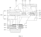
- an embodiment of the present invention discloses an electronic device, and the electronic device includes a housing 100, a first functional module 210, a second functional module 220, and a third functional module.
- the housing 100 provides a foundation for mounting other components of the electronic device.
- the third functional module may be disposed in the housing 100.
- the third functional module includes an acoustic component 230, and the acoustic component 230 may include at least one of sounding components or sound pickup components such as a microphone, a phone receiver, and a speaker.
- a sound guide channel 400 is disposed in the housing 100, and the sound guide channel 400 is configured to transmit sound information.
- the second functional module 220 and the first functional module 210 are mounted on the housing 100, and an assembly gap 221 is present between the second functional module 220 and the first functional module 210, with an opening of the assembly gap 221 being exposed out of an outer surface of the electronic device.
- the assembly gap 221 may be configured to guide sound for the electronic device, and the acoustic component 230 communicates with the assembly gap 221 through the sound guide channel 400.
- the acoustic component 230 is a sound pickup component
- the sound enters the housing 100 through the assembly gap 221, and the assembly gap 221 transmits the sound to the acoustic component 230 through the sound guide channel 400.
- the acoustic component 230 may be a microphone.
- the acoustic component 230 is a sounding component
- the acoustic component 230 may be a phone receiver or a speaker.
- the housing 100 may include a front cover and a rear cover, where the front cover may provide a foundation for mounting a display screen of the electronic device, and the rear cover may be a battery cover of the electronic device.
- the first functional module 210 may be a rear-facing camera module of the electronic device, a flash lamp module, a fingerprint module, a second display module disposed on the rear cover of the housing, or the like. To better describe this embodiment, the following assumes that the first functional module 210 is a rear-facing camera module.
- the second functional module 220 may be a decorative part of the first functional module 210, and therefore the assembly gap 221 is present between the rear-facing camera module, the flash lamp module, or the fingerprint module disposed on the rear and their corresponding decorative rings.
- the first functional module 210 and the second functional module 220 may alternatively be other functional modules, which are not limited herein.
- the assembly gap 221 is present after the first functional module 210 and the second functional module 220 are fitted together. Therefore, the assembly gap 221 between the first functional module 210 and the second functional module 220 can be used to transmit sound information, so that no sound guide hole needs to be provided on the housing 100. This reduces openings on the housing 100, and improves integrity and appearance consistency of the housing 100, thereby guaranteeing a good appearance and texture of the housing and improving user experience.
- the assembly gap 221 is narrower than the sound guide hole, which can effectively prevent ambient vapor and dust from entering the housing 100, thereby improving waterproof and dustproof performance of the electronic device.
- the assembly gap 221 between the first functional module 210 and the second functional module 220 is used to transmit sound information, so that the housing 100 does not need an additionally processed sound guide hole. This optimizes a processing process of the housing 100 and simplifies processing steps of the housing 100, thereby reducing manufacturing costs of the electronic device.
- the assembly gap 221 may be in an elongated strip shape.
- a width of the assembly gap 221 can be reduced to make the assembly gap 221 more concealed.
- the width is a distance between parts of the first functional module 210 and the second functional module 220 which form the assembly gap 221.
- An extension direction of the assembly gap 221 is a length direction of the assembly gap 221.
- a length of the assembly gap 221 can be increased to increase an area of the assembly gap 221, so as to satisfy a sound guide requirement of the acoustic component 230.
- a shape and structure of the assembly gap 221 may be determined by shapes and structures of the first functional module 210 and the second functional module 220.
- the assembly gap 221 may have an arc shape.
- An arc structure has no corners and is much smoother than a linear structure, making the electronic device more aesthetic and further improving user experience.
- an opening is provided on an edge of a side of the second functional module 220 attached to the first functional module 210, and the opening forms the assembly gap 221.
- part of material is removed from the edge of the side of the second functional module 220 attached to the first functional module 210, so that the assembly gap 221 between the second functional module 220 and the first functional module 210 is larger, and the area of the assembly gap 221 is increased.
- the assembly gap 221 can transmit more sound information, which improves the performance of the acoustic component 230, allowing for better sound quality of the electronic device.
- the opening may be in an elongated strip shape, or may certainly be in other shapes, which is not limited herein.
- an opening may alternatively be provided on an edge of a side of the first functional module 210 attached to the second functional module 220, which can achieve the same technical effects: larger area of the assembly gap 221 allows the assembly gap 221 to transmit more sound information, thereby improving the performance of the acoustic component 230 and allowing for better sound quality of the electronic device.
- the first functional module 210 may include a first functional component and a module bracket.
- the first functional component is mounted on the module bracket, the first functional component and the module bracket are exposed out of an outer surface of the housing 100, and the assembly gap 221 is formed between the module bracket and the second functional module 220.
- the first functional module 210 when the first functional module 210 is a camera module, the first functional component may include a camera and other electronic components, and the module bracket provides a foundation for mounting the camera and other electronic components.
- ambient dust and vapor can enter the housing 100 along the assembly gap 221, which may cause the sound guide hole of the acoustic component 230 to be blocked or electronic components of the acoustic component 230 to be short-circuited, resulting in damage to the acoustic component 230 and low safety and reliability of the electronic device.
- the sound guide channel 400 may include a first sound guide segment 410, a second sound guide segment 420, and a third sound guide segment 430 that are in sequential communication, where the first sound guide segment 410 communicates with the assembly gap 221, the acoustic component 230 is located on an end of the third sound guide segment 430 facing away from the second sound guide segment 420, a central axis of the first sound guide segment 410 intersects with a central axis of the second sound guide segment 420, and the central axis of the first sound guide segment 410 is parallel to a central axis of the third sound guide segment 430.
- the sound guide channel 400 is of a bending structure, so that a side wall of each sound guide segment can stop dust and vapor.
- a long sound guide channel 400 allows most of the dust and vapor to settle on the side wall of each sound guide segment, so that the dust and vapor cannot easily reach a mounting position of the acoustic component 230, and the sound guide hole of the acoustic component 230 is not easily blocked, allowing for good sound quality of the acoustic component 230.
- an included angle between the central axis of the first sound guide segment 410 and the central axis of the second sound guide segment 420 may be 90°.
- the central axis of the first sound guide segment 410 may be perpendicular to the central axis of the second sound guide segment 420.
- the sound guide channel 400 has a compact structure, so that the sound guide channel 400 occupies a small space of the housing 100.
- the included angle between the central axis of the first sound guide segment 410 and the central axis of the second sound guide segment 420 may alternatively be other angles, such as 30°, 45°, or 60°. A specific included angle is not limited in the present invention.
- the central axis of the first sound guide segment 410 may intersect with the central axis of the second sound guide segment 420, and the central axis of the first sound guide segment 410 may be parallel to the central axis of the third sound guide segment 430.
- the second sound guide segment 420 may guide the third sound guide segment 430 to an edge position of the housing 100, so that the acoustic component 230 is closer to the edge position of the housing 100, thereby optimizing a structure of the electronic device.
- a connection channel 222 may be formed between the first functional module 210 and the second functional module 220, the first sound guide segment 410 and the assembly gap 221 are staggered, and the first sound guide segment 410 communicates with the assembly gap 221 through the connection channel 222.
- the assembly gap 221, the connection channel 222, and the first sound guide segment 410 form a bending structure, and a side wall of the bending structure can stop the dust and vapor.
- the dust and vapor can be attached to the side wall of the bending structure, which can prevent the dust and vapor from entering the acoustic component 230, so that the sound guide hole of the acoustic component 230 is not easily blocked and the electronic components of the acoustic component 230 are not easily short-circuited or damaged, further improving safety and reliability of the electronic device.
- the connection channel 222 is formed by the module bracket and part of the second functional module 220 not exposed out of a surface of the housing 100.
- the electronic device disclosed in the embodiments of the present invention may further include a main board bracket 510, where the main board bracket 510 is configured for mounting an electronic component of the electronic device, the main board bracket 510 is disposed in the housing 100, the first sound guide segment 410 may be provided on the first functional module 210, the second sound guide segment 420 and the third sound guide segment 430 may be provided on the main board bracket 510, and the first sound guide segment 410 forms an included angle with the second sound guide segment 420 and the third sound guide segment 430.
- the second sound guide segment 420 is formed by pouring, the second sound guide segment 420 is located in the inside of the main board bracket 510, and the main board bracket 510 is difficult to demould, resulting in difficult processing and high costs of the electronic device.
- the electronic device disclosed in the embodiments of the present invention further includes a cover plate 520, where the cover plate 520 may be located in the housing 100, a first groove may be provided on a side of the main board bracket 510 facing toward the first functional module 210, the cover plate 520 covers a notch of the first groove, and in this case, the cover plate 520 and the first groove can form the second sound guide segment 420.
- One end of the cover plate 520 may be provided with a first through hole 521, and the second sound guide segment 420 may communicate with the first sound guide segment 410 through the first through hole 521.
- the third sound guide segment 430 may be provided on a bottom wall of the first groove, and the first through hole 521 and the third sound guide segment 430 are staggered.
- the first groove may be formed on the main board bracket 510 by pouring. Because the first groove is of an open structure, the main board bracket 510 is easy to demould. Then the cover plate 520 covers the notch of the first groove to form the second sound guide segment 420. This solution allows the second sound guide segment 420 to be easily processed, thereby reducing processing difficulty and costs of the electronic device.
- the cover plate 520 may be bonded to the main board bracket 510 by using a double-sided adhesive tape.
- the cover plate 520 may be a PET (Polyethylene terephthalate) plate or a metal plate.
- PET Polyethylene terephthalate
- the cover plate 520 reinforces the main board bracket 510, enhancing overall rigidity of the main board bracket 510.
- the first sound guide segment 410 may be disposed on the first functional module 210, and the second sound guide segment 420 may be disposed on the main board bracket 510.
- a gap is present between the first sound guide segment 410 and the second sound guide segment 420, and sound can enter the gap, leading to sound leakage of the electronic device and seriously affecting sound quality of the electronic device.
- the electronic device disclosed in the embodiments of the present invention may further include a first sealing member 610, where the first functional module 210 is sealedly connected to the cover plate 520 through the first sealing member 610, a first bypass hole 611 is provided on a part of the first sealing member 610 opposite the first through hole 521, and the first sound guide segment 410 and the second sound guide segment 420 communicate with the first through hole 521 through the first bypass hole 611.
- the first sealing member 610 can plug the gap between the first sound guide segment 410 and the second sound guide segment 420 to prevent the sound leakage of the electronic device, allowing for good sound quality of the electronic device.
- the first sealing member 610 can block dust and vapor in the sound guide channel 400, thereby preventing the dust and vapor from damaging the electronic component of the electronic device.
- the first sealing member 610 may be made of a material such as silicone or rubber.
- the cover plate 520 overlaps on a plate surface of the main board bracket 510, such that the main board bracket 510 and the cover plate 520 are stacked high.
- a stacking structure of the main board bracket 510 and the cover plate 520 occupies much space of the housing 100, making the electronic device thicker and affecting user experience.
- a second groove 511 may be further provided on the side of the main board bracket 510 facing toward the first functional module 210.
- the first groove may be provided at the bottom of the second groove 511, the notch of the first groove is located at the bottom of the second groove 511, the cover plate 520 overlaps on the bottom of the second groove 511, the first groove and the second groove 511 may form a sinking platform structure, and at least part of the cover plate 520 is located in the second groove 511.
- at least part of the cover plate 520 can be hidden in the second groove 511, so that the volume of the cover plate 520 exposed is reduced. Therefore, a stacking height of the main board bracket 510 and the cover plate 520 is small, and the stacking structure of the main board bracket 510 and the cover plate 520 occupies only a small space of the housing 100, allowing the electronic device to be thin.
- the electronic device disclosed in the embodiments of the present invention may further include a circuit board 530, and the circuit board 530 is configured for mounting the electronic component of the electronic device.
- the circuit board 530 may be disposed on a side of the main board bracket 510 facing away from the first functional module 210, the circuit board 530 may be provided with a second through hole 531, the acoustic component 230 may be disposed on a side of the circuit board 530 facing away from the main board bracket 510, and the acoustic component 230 communicates with the third sound guide segment 430 through the second through hole 531.
- the acoustic component 230 may be disposed on the side of the circuit board 530 facing away from the main board bracket 510, so that the acoustic component 230 does not interfere with the main board bracket 510, thereby improving reliability of the electronic device.
- the circuit board 530 may be a main board of the electronic device or a secondary board of the electronic device.
- the circuit board 530 may be a rigid printed circuit board or a flexible printed circuit board.
- the circuit board 530 may be a printed circuit board or a rigid-flex printed circuit board, or the circuit board 530 includes a flexible printed circuit board and a reinforcing board that are attached to each other.
- the circuit board 530 may be a printed circuit board or a rigid-flex printed circuit board, or the circuit board 530 includes a flexible printed circuit board and a reinforcing board that are attached to each other.
- other structures and forms may also be used, which are not limited herein.
- the electronic device disclosed in the embodiments of the present invention may further include a second sealing member 620.
- the circuit board 530 may be sealedly connected to the main board bracket 510 through the second sealing member 620, a second bypass hole 621 may be provided on a part of the second sealing member 620 opposite the second through hole 531, and the third sound guide segment 430 communicates with the second through hole 531 through the second bypass hole 621.
- the second sealing member 620 can plug a gap between the third sound guide segment 430 and the second through hole 531 to prevent sound leakage of the electronic device, thereby further improving the sound quality of the electronic device.
- the second sealing member 620 may be made of a material such as silicone or rubber.
- a third groove may also be provided on the side of the main board bracket 510 facing away from the first functional module 210, and the second sealing member 620 is disposed in the third groove.
- the second sealing member 620 can be hidden in the third groove, so that volume of the second sealing member 620 exposed is reduced, reducing a stacking height of a structure formed by the main board bracket 510, the second sealing member 620, and the circuit board 530.
- the structure formed by the main board bracket 510, the second sealing member 620, and the circuit board 530 occupies only a small space of the housing 100, allowing the electronic device to be thin.
- the electronic device disclosed in the embodiments of the present invention may further include a dustproof portion 630, and the dustproof portion 630 may be disposed between the third sound guide segment 430 and the second through hole 531.
- the dustproof portion 630 can block most of the dust in the third sound guide segment 430, so that the dust cannot easily enter the second through hole 531. Only a small amount of dust in the second through hole 531 will not affect the sound quality of the acoustic component 230.
- the dustproof portion 630 may be sandwiched between the main board bracket 510 and the circuit board 530, so that the main board bracket 510 does not need to be provided with a part for mounting the dustproof portion 630, allowing the dustproof portion 630 to be mounted easily.
- the first functional module 210 may have a disc shape
- the second functional module 220 may have a ring shape
- the second functional module 220 may be disposed around the first functional module 210
- the assembly gap 221 may have an annular shape
- part of the assembly gap 221 communicates with the sound guide channel 400.
- the assembly gap 221 may be of a smooth annular structure without any corners, making the electronic device more aesthetic and further improving user experience.
- the assembly gap 221 communicates with the sound guide channel 400.
- the annular assembly gap 221 can collect sound or produce sound for the electronic device, thereby implementing a stereo effect of the electronic device.
- the large area of the assembly gap 221 allows for good sound quality of the electronic device.
- the electronic device disclosed in the embodiments of the present invention may be a device such as a smart phone, a tablet computer, an e-book reader, a wearable device (such as a smartwatch), or an electronic game console.
- a device such as a smart phone, a tablet computer, an e-book reader, a wearable device (such as a smartwatch), or an electronic game console.
- the embodiments of the present invention do not limit the specific type of the electronic device.
Landscapes
- Engineering & Computer Science (AREA)
- Signal Processing (AREA)
- Physics & Mathematics (AREA)
- Acoustics & Sound (AREA)
- Microelectronics & Electronic Packaging (AREA)
- Telephone Set Structure (AREA)
- Details Of Audible-Bandwidth Transducers (AREA)
- Casings For Electric Apparatus (AREA)
Claims (13)
- Elektronische Vorrichtung, umfassend ein Gehäuse (100), ein erstes Funktionsmodul (210), ein zweites Funktionsmodul (220) und ein drittes Funktionsmodul, wobei das dritte Funktionsmodul in dem Gehäuse (100) angeordnet ist, das dritte Funktionsmodul ein akustisches Bauteil (230) umfasst, ein Schallführungskanal (400) in dem Gehäuse (100) angeordnet ist, das zweite Funktionsmodul (220) und das erste Funktionsmodul (210) an dem Gehäuse (100) montiert sind, wobei zwischen dem zweiten Funktionsmodul (220) und dem ersten Funktionsmodul (210) ein Montagespalt (221) vorhanden ist, und das akustische Bauteil (230) durch den Schallführungskanal (400) mit dem Montagespalt (221) kommuniziert.
- Elektronische Vorrichtung nach Anspruch 1, wobei der Montagespalt (221) eine Bogenform aufweist.
- Elektronische Vorrichtung nach Anspruch 1, wobei eine Öffnung an einem Rand einer Seite des zweiten Funktionsmoduls (220) bereitgestellt ist, das an dem ersten Funktionsmodul (210) angebracht ist, oder eine Öffnung an einem Rand einer Seite des ersten Funktionsmoduls (210) bereitgestellt ist, das an dem zweiten Funktionsmodul (220) angebracht ist, und die Öffnung den Montagespalt (221) bildet.
- Elektronische Vorrichtung nach Anspruch 1, wobei das erste Funktionsmodul (210) ein erstes Funktionsbauteil und eine Modulhalterung umfasst, das erste Funktionsbauteil an der Modulhalterung montiert ist, das erste Funktionsbauteil und die Modulhalterung aus einer Außenfläche des Gehäuses (100) heraus freiliegen, und der Montagespalt (221) zwischen der Modulhalterung und dem zweiten Funktionsmodul (220) ausgebildet ist.
- Elektronische Vorrichtung nach Anspruch 1, wobei der Schallführungskanal (400) ein erstes Schallführungssegment (410), ein zweites Schallführungssegment (420) und ein drittes Schallführungssegment (430) umfasst, die in sequentieller Kommunikation stehen, das erste Schallführungssegment (410) mit dem Montagespalt (221) kommuniziert, sich das akustische Bauteil (230) an einem Ende des dritten Schallführungssegments (430) befindet, das von dem zweiten Schallführungssegment (420) abgewandt ist, eine Mittelachse des ersten Schallführungssegments (410) eine Mittelachse des zweiten Schallführungssegments (420) schneidet, und die Mittelachse des ersten Schallführungssegments (410) parallel zu einer Mittelachse des dritten Schallführungssegments (430) verläuft.
- Elektronische Vorrichtung nach Anspruch 5, wobei ein Verbindungskanal (222) zwischen dem ersten Funktionsmodul (210) und dem zweiten Funktionsmodul (220) ausgebildet ist, das erste Schallführungssegment (410) und der Montagespalt (221) versetzt angeordnet sind, und das erste Schallführungssegment (410) durch den Verbindungskanal (222) mit dem Montagespalt (221) kommuniziert.
- Elektronische Vorrichtung nach Anspruch 5, wobei die elektronische Vorrichtung ferner eine Hauptplatinenhalterung (510) und eine Abdeckplatte (520) umfasst, wobei sowohl die Hauptplatinenhalterung (510) als auch die Abdeckplatte (520) sich in dem Gehäuse (100) befinden, eine erste Nut auf einer Seite der Hauptplatinenhalterung (510) bereitgestellt ist, die dem ersten Funktionsmodul (210) zugewandt ist, die Abdeckplatte (520) eine Kerbe der ersten Nut abdeckt, die Abdeckplatte (520) und die erste Nut das zweite Schallführungssegment (420) bilden, ein Ende der Abdeckplatte (520) mit einem ersten Durchgangsloch (521) versehen ist, das zweite Schallführungssegment (420) durch das erste Durchgangsloch (521) mit dem ersten Schallführungssegment (410) kommuniziert, das dritte Schallführungssegment (430) an einer Bodenwand der ersten Nut bereitgestellt ist, und das erste Durchgangsloch (521) und das dritte Schallführungssegment (430) versetzt angeordnet sind.
- Elektronische Vorrichtung nach Anspruch 7, ferner umfassend ein erstes Dichtungselement (610), wobei das erste Funktionsmodul (210) durch das erste Dichtungselement (610) abdichtend mit der Abdeckplatte (520) verbunden ist, ein erstes Umgehungsloch (611) an einem Teil des ersten Dichtungselements (610) gegenüber dem ersten Durchgangsloch (521) bereitgestellt ist, und das erste Schallführungssegment (410) und das zweite Schallführungssegment (420) durch das erste Umgehungsloch (611) mit dem ersten Durchgangsloch (521) kommunizieren.
- Elektronische Vorrichtung nach Anspruch 7, wobei eine zweite Nut (511) ferner auf der Seite der Hauptplatinenhalterung (510) bereitgestellt ist, die dem ersten Funktionsmodul (210) zugewandt ist, die erste Nut am Boden der zweiten Nut (511) bereitgestellt ist, die erste Nut und die zweite Nut (511) eine sinkende Plattformstruktur bilden, und sich zumindest ein Teil der Abdeckplatte (520) in der zweiten Nut (511) befindet.
- Elektronische Vorrichtung nach Anspruch 7, wobei die elektronische Vorrichtung ferner eine Leiterplatte (530) umfasst, die Leiterplatte (530) auf einer Seite der Hauptplatinenhalterung (510) angeordnet ist, die von dem ersten Funktionsmodul (210) abgewandt ist, die Leiterplatte (530) mit einem zweiten Durchgangsloch (531) versehen ist, das akustische Bauteil (230) auf einer Seite der Leiterplatte (530) angeordnet ist, die von der Hauptplatinenhalterung (510) abgewandt ist, und das akustische Bauteil (230) durch das zweite Durchgangsloch (531) mit dem dritten Schallführungssegment (430) kommuniziert.
- Elektronische Vorrichtung nach Anspruch 10, ferner umfassend ein zweites Dichtungselement (620), wobei eine dritte Nut auf der Seite der Hauptplatinenhalterung (510) bereitgestellt ist, die von dem ersten Funktionsmodul (210) abgewandt ist, das zweite Dichtungselement (620) in der dritten Nut angeordnet ist, die Leiterplatte (530) durch das zweite Dichtungselement (620) abdichtend mit der Hauptplatinenhalterung (510) verbunden ist, ein zweites Umgehungsloch (621) an einem Teil des zweiten Dichtungselements (620) gegenüber dem zweiten Durchgangsloch (531) bereitgestellt ist, und das dritte Schallführungssegment (430) durch das zweite Umgehungsloch (621) mit dem zweiten Durchgangsloch (531) kommuniziert.
- Elektronische Vorrichtung nach Anspruch 10, wobei die elektronische Vorrichtung ferner einen staubdichten Abschnitt (630) umfasst, und der staubdichte Abschnitt (630) zwischen dem dritten Schallführungssegment (430) und dem zweiten Durchgangsloch (531) angeordnet ist.
- Elektronische Vorrichtung nach Anspruch 1, wobei das erste Funktionsmodul (210) eine Scheibenform aufweist, das zweite Funktionsmodul (220) eine Ringform aufweist, das zweite Funktionsmodul (220) um das erste Funktionsmodul (210) herum angeordnet ist, der Montagespalt (221) ringförmig ist, und zumindest ein Teil des Montagespaltes (221) mit dem Schallführungskanal (400) kommuniziert.
Applications Claiming Priority (2)
| Application Number | Priority Date | Filing Date | Title |
|---|---|---|---|
| CN202010234120.3A CN111405098B (zh) | 2020-03-27 | 2020-03-27 | 电子设备 |
| PCT/CN2021/076999 WO2021190209A1 (zh) | 2020-03-27 | 2021-02-20 | 电子设备 |
Publications (3)
| Publication Number | Publication Date |
|---|---|
| EP4131906A1 EP4131906A1 (de) | 2023-02-08 |
| EP4131906A4 EP4131906A4 (de) | 2023-09-27 |
| EP4131906B1 true EP4131906B1 (de) | 2025-06-18 |
Family
ID=71433715
Family Applications (1)
| Application Number | Title | Priority Date | Filing Date |
|---|---|---|---|
| EP21775326.8A Active EP4131906B1 (de) | 2020-03-27 | 2021-02-20 | Elektronisches gerät |
Country Status (7)
| Country | Link |
|---|---|
| US (1) | US12316794B2 (de) |
| EP (1) | EP4131906B1 (de) |
| JP (1) | JP7478837B2 (de) |
| KR (1) | KR102708824B1 (de) |
| CN (1) | CN111405098B (de) |
| ES (1) | ES3035985T3 (de) |
| WO (1) | WO2021190209A1 (de) |
Families Citing this family (7)
| Publication number | Priority date | Publication date | Assignee | Title |
|---|---|---|---|---|
| CN111405098B (zh) | 2020-03-27 | 2022-03-18 | 维沃移动通信有限公司 | 电子设备 |
| CN111405414B (zh) * | 2020-03-27 | 2022-07-15 | 维沃移动通信有限公司 | 电子设备 |
| CN111866242A (zh) * | 2020-07-23 | 2020-10-30 | 维沃移动通信有限公司 | 电子设备 |
| CN111901463B (zh) * | 2020-08-28 | 2022-06-17 | 维沃移动通信有限公司 | 电子设备 |
| CN112616099B (zh) * | 2020-12-18 | 2023-06-23 | 维沃移动通信有限公司 | 电子设备 |
| CN112882539B (zh) * | 2021-02-08 | 2024-04-09 | 维沃移动通信有限公司 | 电子设备及其控制方法和控制装置 |
| CN114520845B (zh) | 2022-04-14 | 2022-10-11 | 北京荣耀终端有限公司 | 终端装置 |
Family Cites Families (27)
| Publication number | Priority date | Publication date | Assignee | Title |
|---|---|---|---|---|
| JP4302548B2 (ja) * | 2004-02-18 | 2009-07-29 | オリンパス株式会社 | カメラ及び電子機器 |
| US7801571B2 (en) * | 2005-11-30 | 2010-09-21 | Motorola Mobility, Inc. | Multi-use acoustic leak path system |
| KR100862294B1 (ko) * | 2007-01-19 | 2008-10-13 | 엘지전자 주식회사 | 휴대 단말기 및 그에 장착되는 사운드 가이드 |
| US8385060B2 (en) * | 2009-08-31 | 2013-02-26 | Apple Inc. | Handheld computing device |
| JP5440286B2 (ja) | 2010-03-15 | 2014-03-12 | 富士通株式会社 | 携帯端末装置 |
| KR101376623B1 (ko) | 2012-02-17 | 2014-03-20 | 엘지전자 주식회사 | 이동 단말기 |
| JP6175261B2 (ja) * | 2013-03-27 | 2017-08-02 | 京セラ株式会社 | マイクロフォンを搭載した電子機器 |
| KR102161546B1 (ko) * | 2014-02-05 | 2020-10-05 | 삼성전자 주식회사 | 전자 기기 및 그의 운용 방법 |
| KR102447909B1 (ko) * | 2016-02-25 | 2022-09-28 | 삼성전자주식회사 | 전자 장치 |
| CN106657485B (zh) * | 2017-03-07 | 2020-05-12 | Oppo广东移动通信有限公司 | 移动终端 |
| CN206629355U (zh) * | 2017-04-01 | 2017-11-10 | 深圳天珑无线科技有限公司 | 便携式设备的外壳组件及便携式设备 |
| EP3653932B1 (de) | 2017-07-11 | 2022-02-23 | Furukawa Electric Co. Ltd. | Led-beleuchtungsvorrichtung mit lautsprecherfunktion und verfahren zum extrahieren von licht und ton aus einer led-beleuchtungsvorrichtung mit lautsprecherfunktion |
| KR102349710B1 (ko) * | 2017-07-26 | 2022-01-12 | 삼성전자주식회사 | 스피커를 포함하는 전자 장치 |
| JP2019054410A (ja) | 2017-09-15 | 2019-04-04 | カシオ計算機株式会社 | 防水構造及び電子機器 |
| CN108429831B (zh) * | 2018-02-28 | 2020-09-08 | Oppo广东移动通信有限公司 | 电子设备 |
| WO2019180626A1 (en) * | 2018-03-21 | 2019-09-26 | Lazy Design Private Limited | Wearable communication device |
| KR102282036B1 (ko) * | 2018-03-22 | 2021-07-27 | 광동 오포 모바일 텔레커뮤니케이션즈 코포레이션 리미티드 | 마이크로폰, 이동 단말기 및 전자 장치 |
| CN110365827B (zh) * | 2018-03-26 | 2021-04-16 | Oppo广东移动通信有限公司 | 电子设备 |
| KR102468959B1 (ko) * | 2018-04-17 | 2022-11-23 | 삼성전자 주식회사 | 전자장치의 관로 구조 및 이를 포함하는 전자장치 |
| KR102614049B1 (ko) * | 2019-02-18 | 2023-12-15 | 삼성전자주식회사 | 스피커를 포함하는 전자 장치 |
| CN209448766U (zh) * | 2019-02-27 | 2019-09-27 | 维沃移动通信有限公司 | 移动终端 |
| CN110087167B (zh) | 2019-04-26 | 2021-01-26 | 维沃移动通信有限公司 | 终端设备 |
| CN110035341B (zh) * | 2019-05-16 | 2024-07-26 | 无锡睿勤科技有限公司 | 电子设备的麦克风结构和电子设备 |
| KR102625212B1 (ko) * | 2019-08-01 | 2024-01-16 | 삼성전자주식회사 | 오디오 입력 경로를 포함하는 카메라 브라켓 및 이를 포함하는 전자 장치 |
| CN110913048B (zh) * | 2019-11-29 | 2021-09-28 | 维沃移动通信有限公司 | 电子设备 |
| CN111405098B (zh) * | 2020-03-27 | 2022-03-18 | 维沃移动通信有限公司 | 电子设备 |
| US12256032B2 (en) * | 2021-03-02 | 2025-03-18 | Apple Inc. | Handheld electronic device |
-
2020
- 2020-03-27 CN CN202010234120.3A patent/CN111405098B/zh active Active
-
2021
- 2021-02-20 ES ES21775326T patent/ES3035985T3/es active Active
- 2021-02-20 WO PCT/CN2021/076999 patent/WO2021190209A1/zh not_active Ceased
- 2021-02-20 EP EP21775326.8A patent/EP4131906B1/de active Active
- 2021-02-20 KR KR1020227036715A patent/KR102708824B1/ko active Active
- 2021-02-20 JP JP2022559291A patent/JP7478837B2/ja active Active
-
2022
- 2022-09-12 US US17/942,418 patent/US12316794B2/en active Active
Also Published As
| Publication number | Publication date |
|---|---|
| KR102708824B1 (ko) | 2024-09-23 |
| US20230007109A1 (en) | 2023-01-05 |
| JP2023519015A (ja) | 2023-05-09 |
| CN111405098B (zh) | 2022-03-18 |
| EP4131906A4 (de) | 2023-09-27 |
| CN111405098A (zh) | 2020-07-10 |
| EP4131906A1 (de) | 2023-02-08 |
| KR20220157469A (ko) | 2022-11-29 |
| JP7478837B2 (ja) | 2024-05-07 |
| US12316794B2 (en) | 2025-05-27 |
| ES3035985T3 (en) | 2025-09-11 |
| WO2021190209A1 (zh) | 2021-09-30 |
Similar Documents
| Publication | Publication Date | Title |
|---|---|---|
| EP4131906B1 (de) | Elektronisches gerät | |
| CN111405414B (zh) | 电子设备 | |
| US11917347B2 (en) | Electronic device including acoustic module | |
| CN111405413A (zh) | 电子设备 | |
| EP4221250B1 (de) | Elektronische vorrichtung | |
| US12028665B2 (en) | Terminal device | |
| CN211830849U (zh) | 电子设备 | |
| CN109413246B (zh) | 壳体组件及电子设备 | |
| CN106878563B (zh) | 移动终端 | |
| CN108429831B (zh) | 电子设备 | |
| WO2019179352A1 (zh) | 移动终端 | |
| US11425504B2 (en) | Acoustic module and electronic product | |
| CN108429826B (zh) | 电子设备 | |
| CN110113460A (zh) | 电子设备 | |
| CN111901463A (zh) | 电子设备 | |
| EP4171057B1 (de) | Lautsprecheranordnung und elektronische vorrichtung | |
| CN111182425A (zh) | 电子设备 | |
| CN108494920B (zh) | 功能组件及电子设备 | |
| CN112911037A (zh) | 电子设备 | |
| CN108494905A (zh) | 电子组件和电子设备 |
Legal Events
| Date | Code | Title | Description |
|---|---|---|---|
| STAA | Information on the status of an ep patent application or granted ep patent |
Free format text: STATUS: THE INTERNATIONAL PUBLICATION HAS BEEN MADE |
|
| PUAI | Public reference made under article 153(3) epc to a published international application that has entered the european phase |
Free format text: ORIGINAL CODE: 0009012 |
|
| STAA | Information on the status of an ep patent application or granted ep patent |
Free format text: STATUS: REQUEST FOR EXAMINATION WAS MADE |
|
| 17P | Request for examination filed |
Effective date: 20221024 |
|
| AK | Designated contracting states |
Kind code of ref document: A1 Designated state(s): AL AT BE BG CH CY CZ DE DK EE ES FI FR GB GR HR HU IE IS IT LI LT LU LV MC MK MT NL NO PL PT RO RS SE SI SK SM TR |
|
| DAV | Request for validation of the european patent (deleted) | ||
| DAX | Request for extension of the european patent (deleted) | ||
| A4 | Supplementary search report drawn up and despatched |
Effective date: 20230824 |
|
| RIC1 | Information provided on ipc code assigned before grant |
Ipc: H04M 1/02 20060101ALI20230818BHEP Ipc: H04M 1/03 20060101AFI20230818BHEP |
|
| GRAP | Despatch of communication of intention to grant a patent |
Free format text: ORIGINAL CODE: EPIDOSNIGR1 |
|
| STAA | Information on the status of an ep patent application or granted ep patent |
Free format text: STATUS: GRANT OF PATENT IS INTENDED |
|
| RIC1 | Information provided on ipc code assigned before grant |
Ipc: H04M 1/02 20060101ALI20250210BHEP Ipc: H04M 1/03 20060101AFI20250210BHEP |
|
| INTG | Intention to grant announced |
Effective date: 20250227 |
|
| GRAS | Grant fee paid |
Free format text: ORIGINAL CODE: EPIDOSNIGR3 |
|
| GRAA | (expected) grant |
Free format text: ORIGINAL CODE: 0009210 |
|
| STAA | Information on the status of an ep patent application or granted ep patent |
Free format text: STATUS: THE PATENT HAS BEEN GRANTED |
|
| AK | Designated contracting states |
Kind code of ref document: B1 Designated state(s): AL AT BE BG CH CY CZ DE DK EE ES FI FR GB GR HR HU IE IS IT LI LT LU LV MC MK MT NL NO PL PT RO RS SE SI SK SM TR |
|
| REG | Reference to a national code |
Ref country code: GB Ref legal event code: FG4D |
|
| REG | Reference to a national code |
Ref country code: CH Ref legal event code: EP |
|
| REG | Reference to a national code |
Ref country code: DE Ref legal event code: R096 Ref document number: 602021032504 Country of ref document: DE |
|
| REG | Reference to a national code |
Ref country code: CH Ref legal event code: EP |
|
| REG | Reference to a national code |
Ref country code: IE Ref legal event code: FG4D |
|
| REG | Reference to a national code |
Ref country code: NL Ref legal event code: FP |
|
| REG | Reference to a national code |
Ref country code: ES Ref legal event code: FG2A Ref document number: 3035985 Country of ref document: ES Kind code of ref document: T3 Effective date: 20250911 |
|
| PG25 | Lapsed in a contracting state [announced via postgrant information from national office to epo] |
Ref country code: FI Free format text: LAPSE BECAUSE OF FAILURE TO SUBMIT A TRANSLATION OF THE DESCRIPTION OR TO PAY THE FEE WITHIN THE PRESCRIBED TIME-LIMIT Effective date: 20250618 |
|
| REG | Reference to a national code |
Ref country code: LT Ref legal event code: MG9D |
|
| PG25 | Lapsed in a contracting state [announced via postgrant information from national office to epo] |
Ref country code: GR Free format text: LAPSE BECAUSE OF FAILURE TO SUBMIT A TRANSLATION OF THE DESCRIPTION OR TO PAY THE FEE WITHIN THE PRESCRIBED TIME-LIMIT Effective date: 20250919 Ref country code: NO Free format text: LAPSE BECAUSE OF FAILURE TO SUBMIT A TRANSLATION OF THE DESCRIPTION OR TO PAY THE FEE WITHIN THE PRESCRIBED TIME-LIMIT Effective date: 20250918 |
|
| PG25 | Lapsed in a contracting state [announced via postgrant information from national office to epo] |
Ref country code: BG Free format text: LAPSE BECAUSE OF FAILURE TO SUBMIT A TRANSLATION OF THE DESCRIPTION OR TO PAY THE FEE WITHIN THE PRESCRIBED TIME-LIMIT Effective date: 20250618 |
|
| PG25 | Lapsed in a contracting state [announced via postgrant information from national office to epo] |
Ref country code: HR Free format text: LAPSE BECAUSE OF FAILURE TO SUBMIT A TRANSLATION OF THE DESCRIPTION OR TO PAY THE FEE WITHIN THE PRESCRIBED TIME-LIMIT Effective date: 20250618 |
|
| PG25 | Lapsed in a contracting state [announced via postgrant information from national office to epo] |
Ref country code: RS Free format text: LAPSE BECAUSE OF FAILURE TO SUBMIT A TRANSLATION OF THE DESCRIPTION OR TO PAY THE FEE WITHIN THE PRESCRIBED TIME-LIMIT Effective date: 20250918 |
|
| PG25 | Lapsed in a contracting state [announced via postgrant information from national office to epo] |
Ref country code: LV Free format text: LAPSE BECAUSE OF FAILURE TO SUBMIT A TRANSLATION OF THE DESCRIPTION OR TO PAY THE FEE WITHIN THE PRESCRIBED TIME-LIMIT Effective date: 20250618 |
|
| PG25 | Lapsed in a contracting state [announced via postgrant information from national office to epo] |
Ref country code: PT Free format text: LAPSE BECAUSE OF FAILURE TO SUBMIT A TRANSLATION OF THE DESCRIPTION OR TO PAY THE FEE WITHIN THE PRESCRIBED TIME-LIMIT Effective date: 20251020 |
|
| REG | Reference to a national code |
Ref country code: AT Ref legal event code: MK05 Ref document number: 1805264 Country of ref document: AT Kind code of ref document: T Effective date: 20250618 |
|
| PG25 | Lapsed in a contracting state [announced via postgrant information from national office to epo] |
Ref country code: IS Free format text: LAPSE BECAUSE OF FAILURE TO SUBMIT A TRANSLATION OF THE DESCRIPTION OR TO PAY THE FEE WITHIN THE PRESCRIBED TIME-LIMIT Effective date: 20251018 |
|
| PG25 | Lapsed in a contracting state [announced via postgrant information from national office to epo] |
Ref country code: AT Free format text: LAPSE BECAUSE OF FAILURE TO SUBMIT A TRANSLATION OF THE DESCRIPTION OR TO PAY THE FEE WITHIN THE PRESCRIBED TIME-LIMIT Effective date: 20250618 Ref country code: SM Free format text: LAPSE BECAUSE OF FAILURE TO SUBMIT A TRANSLATION OF THE DESCRIPTION OR TO PAY THE FEE WITHIN THE PRESCRIBED TIME-LIMIT Effective date: 20250618 |
|
| PGFP | Annual fee paid to national office [announced via postgrant information from national office to epo] |
Ref country code: FR Payment date: 20251231 Year of fee payment: 6 |
|
| PG25 | Lapsed in a contracting state [announced via postgrant information from national office to epo] |
Ref country code: CZ Free format text: LAPSE BECAUSE OF FAILURE TO SUBMIT A TRANSLATION OF THE DESCRIPTION OR TO PAY THE FEE WITHIN THE PRESCRIBED TIME-LIMIT Effective date: 20250618 |
|
| PG25 | Lapsed in a contracting state [announced via postgrant information from national office to epo] |
Ref country code: PL Free format text: LAPSE BECAUSE OF FAILURE TO SUBMIT A TRANSLATION OF THE DESCRIPTION OR TO PAY THE FEE WITHIN THE PRESCRIBED TIME-LIMIT Effective date: 20250618 |
|
| PG25 | Lapsed in a contracting state [announced via postgrant information from national office to epo] |
Ref country code: EE Free format text: LAPSE BECAUSE OF FAILURE TO SUBMIT A TRANSLATION OF THE DESCRIPTION OR TO PAY THE FEE WITHIN THE PRESCRIBED TIME-LIMIT Effective date: 20250618 |
|
| PG25 | Lapsed in a contracting state [announced via postgrant information from national office to epo] |
Ref country code: SK Free format text: LAPSE BECAUSE OF FAILURE TO SUBMIT A TRANSLATION OF THE DESCRIPTION OR TO PAY THE FEE WITHIN THE PRESCRIBED TIME-LIMIT Effective date: 20250618 |
|
| PGFP | Annual fee paid to national office [announced via postgrant information from national office to epo] |
Ref country code: NL Payment date: 20260106 Year of fee payment: 6 |
|
| PGFP | Annual fee paid to national office [announced via postgrant information from national office to epo] |
Ref country code: GB Payment date: 20260106 Year of fee payment: 6 |
|
| PGFP | Annual fee paid to national office [announced via postgrant information from national office to epo] |
Ref country code: ES Payment date: 20260305 Year of fee payment: 6 |
|
| PG25 | Lapsed in a contracting state [announced via postgrant information from national office to epo] |
Ref country code: DK Free format text: LAPSE BECAUSE OF FAILURE TO SUBMIT A TRANSLATION OF THE DESCRIPTION OR TO PAY THE FEE WITHIN THE PRESCRIBED TIME-LIMIT Effective date: 20250618 |
|
| PGFP | Annual fee paid to national office [announced via postgrant information from national office to epo] |
Ref country code: DE Payment date: 20251230 Year of fee payment: 6 |
|
| PGFP | Annual fee paid to national office [announced via postgrant information from national office to epo] |
Ref country code: IT Payment date: 20260122 Year of fee payment: 6 |
|
| PLBE | No opposition filed within time limit |
Free format text: ORIGINAL CODE: 0009261 |
|
| STAA | Information on the status of an ep patent application or granted ep patent |
Free format text: STATUS: NO OPPOSITION FILED WITHIN TIME LIMIT |
|
| REG | Reference to a national code |
Ref country code: CH Ref legal event code: L10 Free format text: ST27 STATUS EVENT CODE: U-0-0-L10-L00 (AS PROVIDED BY THE NATIONAL OFFICE) Effective date: 20260430 |