EP4131909A1 - Mobiles endgerät zur anzeige eines bildes und steuerungsverfahren dafür - Google Patents
Mobiles endgerät zur anzeige eines bildes und steuerungsverfahren dafür Download PDFInfo
- Publication number
- EP4131909A1 EP4131909A1 EP20929224.2A EP20929224A EP4131909A1 EP 4131909 A1 EP4131909 A1 EP 4131909A1 EP 20929224 A EP20929224 A EP 20929224A EP 4131909 A1 EP4131909 A1 EP 4131909A1
- Authority
- EP
- European Patent Office
- Prior art keywords
- area
- mobile terminal
- display
- camera
- image
- Prior art date
- Legal status (The legal status is an assumption and is not a legal conclusion. Google has not performed a legal analysis and makes no representation as to the accuracy of the status listed.)
- Granted
Links
Images










Classifications
-
- G—PHYSICS
- G06—COMPUTING OR CALCULATING; COUNTING
- G06F—ELECTRIC DIGITAL DATA PROCESSING
- G06F1/00—Details not covered by groups G06F3/00 - G06F13/00 and G06F21/00
- G06F1/16—Constructional details or arrangements
- G06F1/1613—Constructional details or arrangements for portable computers
- G06F1/1615—Constructional details or arrangements for portable computers with several enclosures having relative motions, each enclosure supporting at least one I/O or computing function
- G06F1/1624—Constructional details or arrangements for portable computers with several enclosures having relative motions, each enclosure supporting at least one I/O or computing function with sliding enclosures, e.g. sliding keyboard or display
-
- G—PHYSICS
- G06—COMPUTING OR CALCULATING; COUNTING
- G06F—ELECTRIC DIGITAL DATA PROCESSING
- G06F1/00—Details not covered by groups G06F3/00 - G06F13/00 and G06F21/00
- G06F1/16—Constructional details or arrangements
- G06F1/1613—Constructional details or arrangements for portable computers
- G06F1/1626—Constructional details or arrangements for portable computers with a single-body enclosure integrating a flat display, e.g. Personal Digital Assistants [PDAs]
-
- G—PHYSICS
- G06—COMPUTING OR CALCULATING; COUNTING
- G06F—ELECTRIC DIGITAL DATA PROCESSING
- G06F1/00—Details not covered by groups G06F3/00 - G06F13/00 and G06F21/00
- G06F1/16—Constructional details or arrangements
- G06F1/1613—Constructional details or arrangements for portable computers
- G06F1/1633—Constructional details or arrangements of portable computers not specific to the type of enclosures covered by groups G06F1/1615 - G06F1/1626
- G06F1/1637—Details related to the display arrangement, including those related to the mounting of the display in the housing
- G06F1/1652—Details related to the display arrangement, including those related to the mounting of the display in the housing the display being flexible, e.g. mimicking a sheet of paper, or rollable
-
- G—PHYSICS
- G06—COMPUTING OR CALCULATING; COUNTING
- G06F—ELECTRIC DIGITAL DATA PROCESSING
- G06F1/00—Details not covered by groups G06F3/00 - G06F13/00 and G06F21/00
- G06F1/16—Constructional details or arrangements
- G06F1/1613—Constructional details or arrangements for portable computers
- G06F1/1633—Constructional details or arrangements of portable computers not specific to the type of enclosures covered by groups G06F1/1615 - G06F1/1626
- G06F1/1684—Constructional details or arrangements related to integrated I/O peripherals not covered by groups G06F1/1635 - G06F1/1675
- G06F1/1686—Constructional details or arrangements related to integrated I/O peripherals not covered by groups G06F1/1635 - G06F1/1675 the I/O peripheral being an integrated camera
-
- G—PHYSICS
- G06—COMPUTING OR CALCULATING; COUNTING
- G06F—ELECTRIC DIGITAL DATA PROCESSING
- G06F1/00—Details not covered by groups G06F3/00 - G06F13/00 and G06F21/00
- G06F1/16—Constructional details or arrangements
- G06F1/1613—Constructional details or arrangements for portable computers
- G06F1/1633—Constructional details or arrangements of portable computers not specific to the type of enclosures covered by groups G06F1/1615 - G06F1/1626
- G06F1/1684—Constructional details or arrangements related to integrated I/O peripherals not covered by groups G06F1/1635 - G06F1/1675
- G06F1/1694—Constructional details or arrangements related to integrated I/O peripherals not covered by groups G06F1/1635 - G06F1/1675 the I/O peripheral being a single or a set of motion sensors for pointer control or gesture input obtained by sensing movements of the portable computer
-
- G—PHYSICS
- G06—COMPUTING OR CALCULATING; COUNTING
- G06F—ELECTRIC DIGITAL DATA PROCESSING
- G06F3/00—Input arrangements for transferring data to be processed into a form capable of being handled by the computer; Output arrangements for transferring data from processing unit to output unit, e.g. interface arrangements
- G06F3/01—Input arrangements or combined input and output arrangements for interaction between user and computer
- G06F3/017—Gesture based interaction, e.g. based on a set of recognized hand gestures
-
- G—PHYSICS
- G06—COMPUTING OR CALCULATING; COUNTING
- G06F—ELECTRIC DIGITAL DATA PROCESSING
- G06F3/00—Input arrangements for transferring data to be processed into a form capable of being handled by the computer; Output arrangements for transferring data from processing unit to output unit, e.g. interface arrangements
- G06F3/01—Input arrangements or combined input and output arrangements for interaction between user and computer
- G06F3/03—Arrangements for converting the position or the displacement of a member into a coded form
- G06F3/033—Pointing devices displaced or positioned by the user, e.g. mice, trackballs, pens or joysticks; Accessories therefor
- G06F3/0346—Pointing devices displaced or positioned by the user, e.g. mice, trackballs, pens or joysticks; Accessories therefor with detection of the device orientation or free movement in a three-dimensional [3D] space, e.g. 3D mice, 6-DOF [six degrees of freedom] pointers using gyroscopes, accelerometers or tilt-sensors
-
- G—PHYSICS
- G06—COMPUTING OR CALCULATING; COUNTING
- G06F—ELECTRIC DIGITAL DATA PROCESSING
- G06F3/00—Input arrangements for transferring data to be processed into a form capable of being handled by the computer; Output arrangements for transferring data from processing unit to output unit, e.g. interface arrangements
- G06F3/14—Digital output to display device ; Cooperation and interconnection of the display device with other functional units
-
- H—ELECTRICITY
- H04—ELECTRIC COMMUNICATION TECHNIQUE
- H04M—TELEPHONIC COMMUNICATION
- H04M1/00—Substation equipment, e.g. for use by subscribers
- H04M1/02—Constructional features of telephone sets
- H04M1/0202—Portable telephone sets, e.g. cordless phones, mobile phones or bar type handsets
- H04M1/026—Details of the structure or mounting of specific components
- H04M1/0264—Details of the structure or mounting of specific components for a camera module assembly
-
- H—ELECTRICITY
- H04—ELECTRIC COMMUNICATION TECHNIQUE
- H04M—TELEPHONIC COMMUNICATION
- H04M1/00—Substation equipment, e.g. for use by subscribers
- H04M1/02—Constructional features of telephone sets
- H04M1/0202—Portable telephone sets, e.g. cordless phones, mobile phones or bar type handsets
- H04M1/026—Details of the structure or mounting of specific components
- H04M1/0266—Details of the structure or mounting of specific components for a display module assembly
- H04M1/0268—Details of the structure or mounting of specific components for a display module assembly including a flexible display panel
-
- H—ELECTRICITY
- H04—ELECTRIC COMMUNICATION TECHNIQUE
- H04M—TELEPHONIC COMMUNICATION
- H04M1/00—Substation equipment, e.g. for use by subscribers
- H04M1/72—Mobile telephones; Cordless telephones, i.e. devices for establishing wireless links to base stations without route selection
- H04M1/724—User interfaces specially adapted for cordless or mobile telephones
-
- H—ELECTRICITY
- H04—ELECTRIC COMMUNICATION TECHNIQUE
- H04M—TELEPHONIC COMMUNICATION
- H04M1/00—Substation equipment, e.g. for use by subscribers
- H04M1/72—Mobile telephones; Cordless telephones, i.e. devices for establishing wireless links to base stations without route selection
- H04M1/724—User interfaces specially adapted for cordless or mobile telephones
- H04M1/72403—User interfaces specially adapted for cordless or mobile telephones with means for local support of applications that increase the functionality
-
- H—ELECTRICITY
- H04—ELECTRIC COMMUNICATION TECHNIQUE
- H04M—TELEPHONIC COMMUNICATION
- H04M1/00—Substation equipment, e.g. for use by subscribers
- H04M1/02—Constructional features of telephone sets
- H04M1/0202—Portable telephone sets, e.g. cordless phones, mobile phones or bar type handsets
- H04M1/0206—Portable telephones comprising a plurality of mechanically joined movable body parts, e.g. hinged housings
- H04M1/0208—Portable telephones comprising a plurality of mechanically joined movable body parts, e.g. hinged housings characterized by the relative motions of the body parts
- H04M1/0235—Slidable or telescopic telephones, i.e. with a relative translation movement of the body parts; Telephones using a combination of translation and other relative motions of the body parts
- H04M1/0237—Sliding mechanism with one degree of freedom
-
- H—ELECTRICITY
- H04—ELECTRIC COMMUNICATION TECHNIQUE
- H04M—TELEPHONIC COMMUNICATION
- H04M2250/00—Details of telephonic subscriber devices
- H04M2250/12—Details of telephonic subscriber devices including a sensor for measuring a physical value, e.g. temperature or motion
-
- H—ELECTRICITY
- H04—ELECTRIC COMMUNICATION TECHNIQUE
- H04M—TELEPHONIC COMMUNICATION
- H04M2250/00—Details of telephonic subscriber devices
- H04M2250/52—Details of telephonic subscriber devices including functional features of a camera
-
- H—ELECTRICITY
- H04—ELECTRIC COMMUNICATION TECHNIQUE
- H04M—TELEPHONIC COMMUNICATION
- H04M2250/00—Details of telephonic subscriber devices
- H04M2250/60—Details of telephonic subscriber devices logging of communication history, e.g. outgoing or incoming calls, missed calls, messages or URLs
Definitions
- This disclosure relates to a mobile terminal for displaying an image using at least one of a first side and a second side of the mobile terminal and a control method thereof.
- One particular implementation relates to a mobile terminal for displaying an image on a first side and a second side based on a condition of the mobile terminal and a control method thereof.
- a method to change a size of a display as necessary by applying a foldable or rollable display having a sufficient elasticity to the electronic device For example, a portion of a display may be rolled up to a rear side of a mobile terminal, and rolled out or moved as necessary such that an exposed area of the display increases.
- the display When the display is provided to have the portion rolled up to the rear side of the mobile display, the display may be located at each of a front side and the rear side of the mobile display.
- inputs When a user grips and uses the mobile terminal with one hand or both hands, inputs may be simultaneously applied to the front side and the rear side of the mobile terminal. In this case, touch inputs may be recognized by simply the gripping motion, which may unintentionally lead to a touch error. Therefore, there is a desire for a method to effectively control an operation related to the display in consideration of a usage pattern of the mobile terminal when the display is provided at each of the front side and the rear side.
- An aspect provides a mobile terminal and a control method of the mobile terminal to control input sensing for at least one of a front side and a rear side of a display based on a use pattern of the mobile terminal, thereby preventing a false operation, which may occur due to an input to the mobile terminal.
- a mobile terminal including a display including a first area and a second area, wherein the first area is located at a first side of the mobile terminal and the second area is located at a second side facing the first side, a camera disposed on the second side, and a controller.
- the controller is configured to display an image acquired through the camera in the first area and the second area.
- a method of controlling a mobile terminal that includes a display includes a first area and a second area wherein the first area is located at a first side of the mobile terminal and the second area is located at a second side facing the first side and a camera disposed on the second side.
- the method includes acquiring an image through the camera and displaying the acquired image in the first area and the second area.
- FIG. 1 is a block diagram illustrating a mobile terminal (or electronic device) 100 related to an example embodiment of the present disclosure.
- the mobile terminal 100 may include a wireless communication part 110, an input part 120, a sensing part 140, an output part 150, an interface 160, a memory 170, a controller (or processor) 180, and a power supply 190.
- the components illustrated in FIG. 1 are not essential to implementing the electronic apparatus, so the mobile terminal 100 described herein may have more or fewer components than those listed above.
- the wireless communication part 110 may include at least one module that enables wireless communication to be performed between the mobile terminal 100 and a wireless communication system, between the mobile terminal 100 and another mobile terminal 100, or between the mobile terminal 100 and an external server.
- the wireless communication part 110 may include one or more modules that connect the mobile terminal 100 to one or more networks.
- the wireless communication part 110 may include at least one of a broadcast receiver 111, a mobile communication part 112, a wireless Internet part 113, a short-range communication part 114, and a position information part 115.
- the input part 120 may include a camera 121 or an image input part to receive an image signal input, a microphone 122 or an audio input part to receive an audio signal input, or a user input part 123, for example, a touch key and a mechanical key to receive information from a user. Voice data or image data collected by the input part 120 may be analyzed and processed as a control command of the user.
- the sensing part 140 may include one or more sensors to sense at least one of information in the mobile terminal, surrounding environment information of the mobile terminal, or user information.
- the sensing part 140 may include at least one of a proximity sensor 141, an illumination sensor 142, a touch sensor, an acceleration sensor, a magnetic sensor, a gravity (G)-sensor, a gyroscope sensor, a motion sensor, an RGB sensor, an infrared (IR) sensor, an ultrasonic sensor, a finger scan sensor, an optical sensor, for example, a camera (refer to the camera 121), a microphone (refer to the microphone 122), a battery gauge, an environment sensor (for example, a barometer, a hygrometer, a thermometer, a radioactivity sensor, a heat sensor, and a gas detection sensor), and a chemical sensor (for example, an electronic nose, a healthcare sensor, and a biometric sensor).
- the mobile terminal may use a combination of pieces of information sensed in at least two sensors among the a
- the output part 150 may generate a visual, auditory, or tactile output.
- the output part 150 may include at least one of the display 151, an acoustic output part 152, a haptic part 153, and an optical output part 154.
- the display 151 may form a layer structure or an integrated structure with a touch sensor to implement a touch screen.
- the touch screen may also function as the user input part 123 that provides an input interface between the mobile terminal 100 and a user and simultaneously, provide an output interface between the mobile terminal 100 and the user.
- the interface 160 may function as a passage to various types of external devices connected to the mobile terminal 100.
- the interface 160 may include at least one of a wired/wireless headset port, an external charger port, a wired/wireless data port, a memory card port, a port connecting a device equipped with an identification module, an audio input/output (I/O) port, a video I/O port, and an earphone port.
- the mobile terminal 100 may perform an appropriate control associated with the connected external device.
- the memory 170 may store data supporting various functions of the mobile terminal 100.
- the memory 170 may store application programs (or applications) run in the mobile terminal 100, data for operation of the mobile terminal 100, and instructions. At least a portion of the application programs may be downloaded from an external server through wireless communication. Also, at least a portion of the application programs may exist in the mobile terminal 100 for a basic function (for example, call forwarding and outgoing function and message receiving and outgoing function) of the mobile terminal 100 from the time of manufacture.
- the application program may be stored in the memory 170, installed in the mobile terminal 100, and run by the controller 180 to perform an operation (or function) of the mobile terminal.
- the controller 180 generally controls an overall operation of the mobile terminal 100 in addition to operations related to the application programs.
- the controller 180 may process a signal, data, information, and the like input or output through the aforementioned components or run the application program stored in the memory 170, thereby providing information to a user or performing appropriate information or function.
- the power supply 190 may supply power to each component included in the mobile terminal 100 by receiving external or internal power under a control of the controller 180.
- the power supply 190 may include a battery such as a built-in battery or a removable battery.
- At least a portion of the aforementioned components may operate in cooperation with each other to implement an operation, a control, or a control method of the mobile terminal according to various embodiments as described below. Also, the operation, control, or control method of the mobile terminal may be implemented on the mobile terminal through an execution of at least one application program stored in the memory 170.
- FIG. 2 illustrates front views of a mobile terminal in a first state and a second state
- FIG. 3 illustrates rear views of the mobile terminal in the first state and the second state.
- (a) of FIG. 2 and (a) of FIG. 3 illustrate the first state in which the mobile terminal is retracted.
- (b) of FIG. 2 and (b) of FIG. 3 illustrate the second state in which the mobile terminal is extended.
- the mobile terminal 100 in the first state is retracted and has a smaller size when compared to the mobile terminal 100 in the second state.
- a display part or display 151 located at a front side of the mobile terminal 100 may be reduced in size when compared to the second state.
- the mobile terminal 100 may be extended in a first direction D1 in the first state to enter the second state.
- the size of the mobile terminal 100 and the size of the display 151 located at the front side may increase when compared to the first state.
- the size of the display 151 located at a rear side may be reduced as shown in (b) of FIG. 3 .
- a display's portion located at the rear side of the mobile terminal 100 in the first state may move to the front side of the mobile terminal 100 in the second state.
- a direction in which the mobile terminal 100 and the display 151 thereof are extended or enlarged may be referred to as the first direction D1.
- a direction in which the mobile terminal 100 and the display 151 thereof are contracted, retracted, or reduced in the second state to enter the first state may be referred to as a second direction D2.
- a direction vertical to the first direction D1 and the second direction D2 may be referred to as a third direction.
- the following description may be based on a case in which the first direction and the second direction are horizontal directions and the third direction is a vertical direction. In some cases, based on a placement of the mobile terminal 100, the first direction D1 and the second direction D2 may be vertical directions and the third direction may be a horizontal direction.
- the display 151 may use the flexible display 151 to be bent so that a position of the display 151 is changeable.
- the flexible display 151 may be maintained in a flat state like a typical flat panel display and include a display (e.g., electronic paper) to be curved, bent, folded, twisted, or rolled like a paper.
- the flexible display 151 may include a lightweight and durable display fabricated on a thin and flexible substrate.
- the flexible display 151 may be bendable in a predetermined direction like a paper and disposed such that a curvature is changed in the first direction.
- the electronic paper may be a display technology based on characteristics of a general ink, and different from the typical flat panel display in using reflected light.
- the electronic paper may use a twist ball or electrophoresis using a capsule to change information.
- a display area of the flexible display 151 may be a plane.
- the display area In the default state, when the flexible display 151 is deformed by an external force (for example, a state having a limited curvature radius, hereinafter, a deformed state), the display area may be a curved plane.
- information displayed in the deformed state may be visual information displayed on the curved plane.
- the visual information may be implemented by individually controlling light emission of sub-pixels arranged in a matrix form.
- the sub-pixel may be a minimum unit for implementing one color.
- the flexible display 151 may implement a flexible touch screen in combination with a touch sensor.
- the controller 180 of FIG. 1 may perform a control corresponding to the touch input.
- the flexible touch screen may be configured to sense a touch input even in the deformed state as well as the default state.
- the touch sensor may sense a touch (or touch input) applied to the touch screen based on at least one of various touch types including a resistive type, a capacitive type, an infrared type, an ultrasonic type, and a magnetic field type.
- the touch sensor may be configured to convert a change such as a pressure applied to a predetermined portion of the touch screen or a capacitance generated at the predetermined portion into an electrical input signal.
- the touch sensor may be configured to detect a position at which a touch object applying a touch on the touch screen is touched on the touch sensor, an area, a touch pressure, a touch capacitance, and the like.
- the deformation detection part may be provided in the flexible display 151 or a case (a first frame 101 and a second frame 102 described below) to sense information related to the deformation of the flexible display 151.
- the information related to the deformation may include, for example, a direction in which the flexible display is deformed, a degree of deformation, a deformed position, a deformation time, and an acceleration at which the deformed flexible display 151 is restored.
- the information related to the deformation may be various information to be detected in response to the flexible display 151 being bent.
- the controller 180 may change information displayed on the flexible display 151 or generate a control signal for controlling functions of the mobile terminal 100.
- the deformation of the flexible display 151 may vary based on positions of the first frame 101 and the second frame 102. As illustrated in FIG. 2 , since a bent position of the flexible display 151 is determined based on the positions of the first frame 101 and the second frame 102, a front-side exposed area and a bending-deformed position of the flexible display 151 may be calculated based on the positions of the first frame 101and the second frame 102 instead of the deformation detection part of the flexible display 151.
- a state change (to the first state or the second state) of the flexible display 151 for example, a size change of the display 151 occurring at the front side or the rear side of the mobile terminal 100 in response to a size change of the mobile terminal 100 may be manually performed by force applied by a user but not be limited to such a manual manner.
- the mobile terminal 100 or the flexible display 151 may be changed to enter the second state by a command of the user or an application irrespective of the external force applied from the user.
- the mobile terminal 100 may include a driving part 200 described below.
- the flexible display 151 may be rolled and bent at 180° with covering a first-direction side portion of the mobile terminal 100. Based on the side portion of the mobile terminal 100, a portion of the flexible display 151 may be located at the front side of the mobile terminal 100 and another portion of the flexible display 151 may be located at the rear side of the mobile terminal 100.
- the flexible display 151 located at the front side may be referred to as a front-side portion and the flexible display 151 located at the rear side may be referred to as a rear-side portion.
- the mobile terminal may extend in the first direction or retract in the second direction opposite to the first direction as illustrated in FIG. 2 . In this case, an area of the flexible display 151 located at the front side may be changed. In other words, sizes of the front-side portion and the rear-side portion may be changed based on a state change of the mobile terminal.
- a portion of the flexible display 151 located at the front side of the mobile terminal 100 may be unmovably fixed to a front side of the first frame 101 while another portion located at the rear side of the mobile terminal 100 is movably provided at the rear side.
- the display 151 may be inserted or pushed into the second frame 102 or withdrawn or pulled out from the second frame 102 while being rolled up at the second frame 102 based on a moving direction of the second frame 102. Such operation will be further described below along with other related components of the mobile terminal 100.
- the mobile terminal 100 of the present disclosure may include a frame, for example, the first frame 101 and the second frame 102 to mount components therein. As illustrated in FIG. 2 , the frame may be changed in size in the first direction. At least one frame may relatively move so as to be changed in size in the first direction.
- the frame may include an electronic component mounted therein. Also, the flexible display 151 may be located external to the frame.
- the first frame 101 may correspond to a main body of the mobile terminal 100 and have a space for accommodating components between a first front portion 1011 and a first rear portion 1012. Also, the first frame 101 may accommodate, in the space, the second frame 102 that is movably coupled to the first frame 101. Specifically, as illustrated in FIGS. 2 and 5 , the first frame 101 may include the first front portion 1011 that is disposed in the front of the mobile terminal 100 to support the front-side portion of the display 151 and the first rear portion 1012 that is disposed in the rear of the mobile terminal 100 so that various components are mounted therein.
- the first front portion 1011 and the first rear portion 1012 may be separated in a predetermined distance such that a predetermined space is formed therebetween. Also, the first front portion 1011 and the first rear portion 1012 may be connected by a first side portion 1013. The first side portion 1013 may be integrally formed with the first rear portion 1012 or the first front portion 1011.
- the camera 121, the acoustic output part 152, an input and output terminal, the controller 180, and the power supply 190 may be accommodated in the space of the first frame 101 as components of the mobile terminal 100.
- the controller 180 may be a circuit board 181 including an electric circuit and a processor provided to control an operation of the mobile terminal 100.
- the power supply 190 may be a battery 191 and related components.
- the below-described driving part 200 that controls a slide movement of the second frame 102 may be accommodated in the first frame 101.
- the display 151 may have a continuous body and rolled in the mobile terminal 100 to be located both front side and rear side of the mobile terminal 100.
- the display 151 may include a front-side portion located at the front side of the mobile terminal 100, a rear-side portion located at the rear side of the mobile terminal 100, and a side portion located between the front-side portion and the rear-side portion to cover a side surface of the mobile terminal 100.
- the front-side portion and the rear-side portion of the display 151 may be flat and the side portion of the display 151 may be curved. When the side portion is bent to form an angle, the flexible display 151 may be damaged. Thus, the side portion may be provided to be bent with a predetermined curvature.
- the display 151 may include a fixed portion and a variable portion.
- the fixed portion may be a portion fixed to a frame. Since the fixed portion is fixed at the frame, a bending degree of the fixed portion may not be changed so that the fixed portion is maintained in a predetermined shape.
- the variable portion may be a portion in which an angle or position of a bent portion is changeable.
- the variable portion may require a structure for supporting a rear surface of the variable portion in in accordance with a change in angle or position of the bent portion.
- the fixed portion may be coupled to the first frame 101 of the display 151 and located at the front side so as to be a part of the front-side portion.
- the variable portion may include a side portion located in a direction to a side surface of the mobile terminal. In this case, a position of the side portion may be changed based on a position of the second frame 102. An area located at the front side and an area located at the rear side may be changed in size based on the side portion. For example, based on whether being in the first state or the second state, a portion of the variable portion may be the front-side portion and another portion may be the rear-side portion.
- the end portion of the variable portion of the display 151 may be coupled to a sliding frame 103 that guides the end portion to slide on the rear side of the second frame.
- the sliding frame 103 may move on the second frame 102 in the first direction simultaneously when the second frame 102 moves in the first direction. As a result, the sliding frame 103 may move relative to the first frame 101 by a distance twice that of the second frame 102.
- the first rear portion 1012 of the mobile terminal 100 may include an exposed rear portion 1015 that is not covered by the display 151 and is exposed outside even in the first state.
- a typical bar-type terminal may provide a display on only a front side of the terminal.
- a main camera may be mounted on a rear side of the terminal to allow a user to capture an object facing a side opposite to the display while the user is viewing the obj ect through the display.
- another camera may be additionally required on a front side of the terminal.
- the display 151 may be located at both front side and rear side of the mobile terminal 100.
- the display 151 on the same side as the camera 121 that is, the rear-side portion of the display 151 may be used.
- the front-side portion of the display 151 located on the side opposite to the camera 121 may be used.
- the mobile terminal 100 may capture the user and the object facing the side opposite to the user using the single camera 121.
- the camera 121 may include a plurality of cameras having different angles of view such as a wide angle, an ultra-wide angle, a telephoto, and the like.
- a proximity sensor, an acoustic output part, and the like may be located on the exposed rear portion 1015.
- the antenna 116 may be installed thereto.
- an exposure decoration may be attached to protect the camera and sensor of the exposed rear portion 1015.
- a portion corresponding to the camera 121 or the sensing part 140 may be configured to be transparent and another portion may have a predetermined pattern or color in consideration of design so internal components are not be exposed.
- the first side portion 1013 may not be formed on the first-direction side surface and thus, may be open. Since the first side portion 1013 is exposed external to the mobile terminal 100, the interface 160 for connecting a power port or an ear jack, or the user input part 120 such as a volume button may be disposed therein. When including a metal material, the first side portion 1013 may serve as an antenna.
- the second frame 102 may include a second front portion 1021 located in the front of the mobile terminal 100 and a second rear portion 1022 located in the rear of the mobile terminal 100.
- the second front portion 1021 and the second rear portion 1022 may be formed as substantially flat panel members.
- the second frame 102 may accommodate various components and may not interfere with the components accommodated in the first frame 101 during the movement.
- the second front portion 1021 and the second rear portion 1022 may be coupled to each other so that a predetermined space is formed therebetween. Also, the second front portion 1021 and the second rear portion 1022 may be shaped not to interfere with the components included in the first frame 101.
- FIG. 6 illustrates side views of the mobile terminal 100 from the third direction.
- FIG. 6 illustrates the first side portion 1013 of the first frame 101 and a second side portion 1023 of the second frame 102.
- a first-direction end portion of the second frame 102 may not be exposed outside since the flexible display 151 is located.
- a second-direction end portion of the second frame 102 may be open to prevent interference with the first frame 101.
- the second side portion 1023 of the second frame 102 located in the third direction (in the drawings, an upper or lower direction or including both upper and lower directions) may overlap the first side portion 1013 of the first frame 101 not to be exposed outside in the first state. In the second state, however, the second side portion 1023 may be exposed outside because the second frame 102 is pulled out.
- the display 151 may be rolled in the second frame 102 and bent at 180° so as to be located at both front and rear sides of the mobile terminal 100.
- the second frame 102 may include a roller 210 rotatably disposed therein.
- the roller 210 may be disposed at a predetermined position in the second frame 102.
- the display 151 may be flatly spread on the front side and the rear side of the mobile terminal 100.
- a sufficient tensile force may be provided to the display 151.
- the roller 210 may be disposed at the first-direction end portion of the second frame 102.
- the roller 210 may be extended in the second direction and rotatably coupled to the second frame 102.
- the display 151 may be gently bent with a predetermined curvature to be rolled on the roller 210.
- the flexible display 151 may include a first surface exposed outside to display an image and an inner surface facing a frame on the other side.
- the roller 210 may be installed in the second frame 102 to be freely rotatable while contacting the inner surface of the display 151. Practically, the roller 210 may move the display 151 in a lateral direction, that is, a direction vertical to a longitudinal direction of the mobile terminal 100.
- the display 151 having a direction (e.g., the first direction D1 or the second direction D2) different from and relative to the second frame 102 may be moved to the front side or the rear side of the mobile terminal 100 by the tensile force applied from the second frame 102.
- the roller 210 may guide the movement of the display 151 while rotating.
- the roller 210 may be disposed adjacent to the first-direction end portion of the second frame 102 and include a side frame 1024 disposed at the first-direction end portion of the second frame 102 to prevent damage to the display 151 rolled on the roller 210.
- the side frame 1024 may extend in the longitudinal direction of the second frame 102 (e.g., the third direction) to cover the first-direction side portion, so as to protect the roller 210 and the display 151 rolled thereon. Also, the side frame 1024 may be relocated based on a state of the mobile terminal 100.
- the side portion may have a predetermined curvature and be rolled by the roller 210.
- An inner surface of the side frame 1024 may include a curved surface corresponding to the curvature of the side portion.
- the side frame 1024 may substantially form an appearance of the mobile terminal 100 along with the first side portion 1013 of the first frame 101. Also, to minimize interference with the components of the first frame 101 during the movement, a second-direction side portion of the second frame 102 may be omitted.
- the display 151 may be deformed or damaged due to a friction with the second front portion 1021 moving repetitively.
- the second front portion 1021 may be disposed below the first front portion 1011 or inserted between the first front portion 1011 provided as two pieces.
- the second rear portion 1022 of the second frame 102 may be disposed in a rear-side direction of the first rear portion 1012 of the first frame 101.
- a front side of the second rear portion 1022 may face a rear side of the first rear portion 1012.
- the rear side of the first rear portion 1012 may contact the front side of the second rear portion 1022.
- the second rear portion 1022 may be exposed external to the first frame 101, for example, external to the first rear portion 1012 and coupled to the display 151.
- the second frame 102 may extend and retract in the first and second directions D1 and D2 such that a size of the mobile terminal 100, for example, a size of the front side of the mobile terminal 100 is increased or reduced.
- the display 151 may be moved based on the increased or reduced portion of the front side.
- the display 151 may not be moved in response to the front side of the mobile terminal 100 being extended or retracted. For this reason, the display 151 may be movably coupled to the second frame 102.
- the display 151 may include the first area 151a located at the front side of the mobile terminal 100 and the second area 151b coupled to the sliding frame 103 located at the rear side of the mobile terminal 100.
- the display 151 may also include athird area 151c located between the first area 151a and the second area 151b.
- the third area 151c may be bent to cover the roller 210 and may move to the front side or the rear side based on a state change of the mobile terminal 100.
- the sliding frame 103 may be provided as a panel-type member that extends in the longitudinal direction of the mobile terminal 100 (e.g., the third direction),
- the first area 151a, the second area 151b, and the third area 151c may be connected to one another and form a continuous body of the display 151. Also, as described above, to allow the third area 151c to move to the front side or the rear side of the mobile terminal 100 based on a moving direction of the second frame 102, the first area 151a may be unmovably fixed to the front side of the mobile terminal 100 and the second area 151b may be movably provided on the rear side of the mobile terminal 100. Such configuration of the display 151 will be described in detail below.
- the third area 151c may be adjacent to the first area 151a.
- the third area 151c may extend into the second frame 102 to be rolled on the roller 210. Continually, the third area 151c may extend out of the second frame 102 and partially cover the second frame 102, for example, the rear side of the second rear portion 1022. Meanwhile, since the second frame 102, that is, the second rear portion 1022 is adjacent to the first frame 101, for example, the first rear portion 1012 and forms a rear case of the mobile terminal 100 together, it can be understood that the third area 151c is also arranged at the rear side of the first frame 101.
- the second area 151b may be adjacent to the third area 151c and located at the rear side of the mobile terminal 100, for example, the rear side of the second rear portion 1022 of the second frame 102.
- the second area 151b may be coupled to the sliding frame 103 instead of being coupled directly to the second frame 102.
- the first area 151a may be located at the front side of the mobile terminal 100 to be always exposed at the front side irrespective of the movement of the second frame 102.
- the second area 151b may be located at the rear side of the mobile terminal 100 to be always exposed at the rear side irrespective of the movement of the second frame 102.
- the third area 151c may be between the first and second areas 151a and 151b and selectively arranged at the front side or the rear side of the mobile terminal 100 based on the moving direction (e.g., D1, D2) of the second frame 102.
- a first rear portion 1012's portion which is covered by the second area 151b and the third area 151c of the display 151 and the second rear portion 1022 in the first state may be exposed external to the mobile terminal 100.
- the second front portion 1021 of the second frame 102 may be disposed hidden by the first front portion 1011 of the first frame 101. In the second state, however, the second front portion 1021 may be moved out of the first frame 101 to support the third area 151c of the display 151 located at the front side of the mobile terminal 100.
- the third area 151c may be rolled on the roller 210 in the second frame 102 to be curved.
- the third area 151c may extend from the second frame 102 to the front side of the mobile terminal 100 while being rolled on the roller 210 in one direction.
- the third area 151c may be rolled on the roller 210 in a reverse direction to retract from the front side of the mobile terminal 100 to the second frame 102.
- the third area 151c may return from the second frame 102 to the rear side of the mobile terminal 100.
- a rear cover 1025 may be further provided on the rear side of the second rear portion 1022 to prevent an external exposure of the rear-side portion of the display 151 located at the rear side of the mobile terminal 100.
- the rear cover 1025 includes a transparent material, the rear-side portion may also be used even in the first state.
- the rear cover 1025 may cover the sliding frame 103 such that the moving of the sliding frame 103 is not exposed outside.
- the sliding frame 103 and the second and third areas of the display 151 may move in the first direction and the second direction in a space between the second rear portion 1022 and the rear cover 1025.
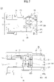
- the motor 201 may use the motor 201 that provides a rotating force as illustrated in FIG. 7 and may also use a linear motor that performs a rectilinear motion. To increase the rotating force provided by the motor 201, a diameter of the motor 201 may also be increased. Referring to FIG. 7 , two motors 201 may be used to provide a predetermined intensity of driving force or more while preventing an increase in thickness in a restricted space of the mobile terminal 100. The second frame 102 moving too fast may lead to damage or false operation. Thus, a planetary gear may be further provided to reduce the speed of the motor 201 so the motor 201 moves at a stable speed. A planetary gear 202 may serve to amplify or attenuate a number of revolutions of the motor 201 using a plurality of disc gears with different numbers of teeth.
- the motor 201 may be fixed to the first frame 101 as shown in (a) of FIG. 7 . Also, as shown in (b) of FIG. 7 , a position of the motor 201 may be fixed even when the mobile terminal 100 enters the second state in response to the second frame 102 moving in the first direction.
- a rack and pinion that converts a rotating force of the motor 201 into the linear motion may be used.
- a pinion gear receiving the rotating force of the motor 201 may be arranged to engage with a rack gear 205 having teeth consecutively arranged in the first direction.
- the pinion gear may be fixed to the first frame 101 along with the motor 201, and the rack gear 205 may be located at the second frame 102.
- the first frame 101 may also be located at the rack gear 205, and the pinion gear may also be located at the second frame 102 along with the motor 201.
- a stopper may be further provided to fix a position between the first frame 101 and the rack gear 205 or the second frame 102 so the mobile terminal 100 is fixedly in the first state or the second state.
- the stopper When the motor 201 is driven in response to current being applied, the stopper may be released to allow movement of the second frame 102.
- the stopper When current is not applied so the motor 201 does not rotate, the stopper may be engaged to fix the second frame 102 and a position of the second frame 102.
- the driving part 200 When the driving part 200 is provided as a pair of driving parts symmetrically disposed in a vertical direction (e.g., the third direction) the driving part 200 may stably move. However, to arrange a battery and the like in consideration of a limited mounting space of the mobile terminal 100, the driving part 200 may be disposed biasedly on one side as shown in (a) of FIG. 7 . In some cases, due to such an asymmetric position of the driving part 200, an upper portion and a lower portion of the second frame 102 may move at different speeds so the second frame 102 is twisted. To prevent this, a linear guide 230 may be further provided in the mobile terminal 100.
- the guide block 232 may be coupled to the first frame 101, the guide rail 231 may be coupled to the second frame 102, and then the guide block 232 and the guide rail 231 may be slidably coupled.
- the guide block 232 in a state of the guide block 232 and the guide rail 231 are coupled, the guide block 232 may be fixed to the first frame 101, and then the second frame 102 may be coupled to the guide rail 231.
- the guide block 232 may include a guide groove into which the guide rail 231 is inserted.
- the guide rail 231 may include a rail groove into which a portion of the guide block 232 is inserted. Projections may be formed on a fastening portion of the guide block 232 and the guide rail 231 so the guide rail 231 and the guide block 232 move in the first direction or the second direction without deviating in a thickness direction of the mobile terminal 100.
- a member formed of a material having a high wear resistance, a low friction resistance, and a self-lubricating property such as polyoxymethylene (POM) or a bearing may be added inside the guide groove.
- POM polyoxymethylene
- FIG. 8 illustrates cross-sectional views taken along lines A-A and B-B of FIG. 2 .
- (a) of FIG. 8 is a cross-sectional view taken along the line A-A of FIG. 2
- (b) of FIG. 8 is a cross-sectional view taken along the line of FIG. 2 .
- the third area 151c located in the rear-side direction may move in the front-side direction.
- a structure for supporting the rear side of the third area 151c moved to the front side may be required.
- the second front portion 1021 located at the front side of the second frame 102 may be located at the rear side of the third area 151c in the second state. However, because the second front portion 1021 may overlap the first front portion 1011 of the first frame 101 in the first state, the first front portion 1011 and the second front portion 1021 may have a level difference therebetween. The level difference between the first front portion 1011 and the second front portion 1021 may create a boundary between the first area 151a and the third area 151c of the flexible display 151.
- a rolling plate 104 may be used as a support structure for filling a space between the second front portion 1021 and the third area 151c of the flexible display 151.
- the rolling plate 104 may be located at the rear side of the flexible display 151 and may have a thickness corresponding to a space between the second front portion 1021 and the flexible display 151 in the second state. As shown in (a) of FIG. 8 , in the first state, the rolling plate 104 may be rolled on the roller 210 and located in a direction to the side surface and the rear side of the mobile terminal 100. Also, the flexible display 151 and the rolling plate 104 may be located between the rear cover 1025 covering the rear-side portion of the display 151 and the second rear portion of the second frame 102. As shown in (b) of FIG. 8 , when switching to the second state, the rolling plate 104 may move to the front side and thus, located in a front portion of the second frame 102.
- FIG. 9 illustrates the rolling plate 104 and the display 151 of the mobile terminal 100 according to an example embodiment.
- the rolling plate 104 may include a plurality of support bars 1041 extended in the third direction.
- the plurality of support bars 1041 may be arranged in parallel in the first direction at preset intervals. Through such arrangement, even when the flexible display 151 is rolled on the roller 210 to be bent, the plurality of support bars 1041 may be prevented from interfering with each other.
- the support bar 1041 may be implemented as an injection-molded object having a predetermined thickness to achieve the stiffness and may include a metal material such as stainless steel (SUS), for example.
- SUS stainless steel
- the plurality of support bars 1041 may be directly attached to the rear side of the display 151. In this case, however, it may take a long time and a lot of defects, which may decrease productivity. Also, in a case of directly processing the display 151, the display 151 may be easily damaged. To prevent this, the mobile terminal 100 may further include a rolling sheet 1045 to fix the plurality of support bars 1041.
- the rolling sheet 1045 may include a metal material, and may use a material having ultra-elasticity to be bending-deformed and maintained as being flat after the bending deformation.
- an ultra-elastic metal sheet such as a thin STS sheet having a thickness of 0.05 millimeters (mm) or less may be used.
- an adhesive tape may be applied to both sides of the rolling sheet 1045.
- the rolling sheet 1045 may have a kerf pattern in which a groove extending in the third direction is provided in plural in the first direction.
- the grooves of the kerf pattern may be formed between the plurality of support bars 1041.
- the grooves may be formed in a side on which the support bars 1041 are attached to the rolling sheet 1045.
- the kerf pattern may be formed in a wedge shape such that a size is large in a surface part of the rolling sheet 1045 and narrowed gradually.
- a material having elasticity such as silicon may be disposed between the support bars 1041 to couple the neighboring support bars 1041 so an angle between the support bars 1041 varies.
- An elastic connecting part may be bent at a position corresponding to the roller 210 and if located at the front side or the rear side, may stretch so that the support bars 1041 are arranged to form a plane.
- the support bars 1041 may form a flat plane corresponding to the rear side of the display 151. Also, as shown in (b) of FIG. 8 , the support bars 1041 may form a curved plane with a predetermined curvature. The support bars 1041 of the curved plane may be in close contact with a curved surface of the roller 210 when the rolling plate 104 is rolled on the roller 210.
- the support bars 1041 may form a plane having one flat surface in contact with the display 151 and the other surface curved with a curvature corresponding to the curvature of the roller 210. In such cases, the support bars 1041 may have maximal thicknesses at a first-directional end and a second-directional end and have a minimum thickness at a center.
- the rolling plate 104 may be located at a position corresponding to the third area 151c, and rolled and bent over the roller 210 to span the front side and the rear side.
- the rolling plate 104 may be connected to the first front portion 1011 of the first frame 101 in the front-side direction and connected to the sliding frame 103 in the rear-side direction.
- the first front portion 1011 of the first frame 101 located at the rear side of the first area 151a, the sliding frame 103 located at the rear side of the second area 151b, and the rolling plate 104 located at the rear side of the third area 151c may contact the display 151 at the same height.
- the rolling plate 104 since the sliding frame 103 moves on the rear side of the mobile terminal 100 and moves in the same space as the rolling plate 104, the rolling plate 104 may have a thickness corresponding to that of the sliding frame 103.
- FIGS. 10 and 11 illustrate a mobile terminal according to an example embodiment of the present disclosure.
- FIG. 10 illustrates an example of displaying an image acquired through a camera on a display located at a first side and a second side of the mobile terminal.
- FIG. 11 illustrates an example of displaying an image acquired through a camera on the display located at the second side of the mobile terminal.
- the displaying of the acquired image may include consecutively displaying images captured by the camera.
- a user may check a region captured by the camera based on the displayed images and store a specific image or video by applying an input like pushing a capture button, to the terminal.
- a display may be located at a first side and a second side of a mobile terminal.
- the display of at least one of the first side and the second side may display content (e.g., an image).
- a first screen 1001 may be displayed on the display of the first side of the mobile terminal.
- the first side may correspond to a front side of the mobile terminal and the second side may correspond to a rear side of the mobile terminal.
- the first screen 1001 may be displayed in a first area of the first side
- the second screen 1002 or the third screen 1003 may be displayed in a second area of the second side.
- the first area may include a predetermined area of the first side and the second area may include a predetermined area of the second side.
- the second screen 1002 or the third screen 1003 of FIG. 10 may be a screen displayed on the display of the second side and may include an image 1050 acquired through a camera.
- the second screen 1002 may be a screen on which a control icon of an application related to the camera briefly appears.
- the third screen 1003 may be a screen on which a control icon (e.g., a first control icon 1055, a second control icon 1054, and a third control icon 1056) appears in detail.
- the second screen 1002 or the third screen 1003 may include a second icon 1052.
- provision of the second screen 1002 or the third screen 1003 may terminate.
- a first screen 1101 with limited functions is displayed on a first side and a second screen 1102 including an image acquired through a camera is displayed on a second side.
- the second screen 1102 may correspond to the third screen 1003 of FIG. 10 but is not limited thereto. Depending on an example, the second screen 1102 may correspond to the second screen 1002 of FIG. 10 .
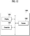
- FIG. 12 is a functional block diagram illustrating a mobile terminal according to an example embodiment of the present disclosure.
- an element of a mobile terminal 1200 may be a unit that processes at least one function or operation, and may be implemented through hardware, software, or a combination of hardware and software.
- the mobile terminal 1200 may include a display 1201, a camera 1202, and a controller 1203.
- the display 1201 may display a variety of information associated with an operation of the mobile terminal 1200.
- the display 1201 may display content related to an application (e.g., camera application) provided in response to an execution of the application or content indicating the application.
- an application e.g., camera application
- the camera 1202 may include a plurality of cameras.
- the camera 1202 may include a plurality of cameras having different lenses.
- the camera 1202 may generate an image by acquiring information on an object or space positioned in a direction facing a lens of the camera 1202 based on the control of the controller 1203 as described below. For example, when a person stands with facing the lens of the camera 1202, an image generated by the camera 1202 may include a person image. Since technology relating to the camera 1202 is easy for those skilled in the art, a detailed description will be omitted.
- the controller 1203 may control the mobile terminal 1200 or components of the mobile terminal 1200.
- the controller 1203 may execute a command or application program stored in a memory to control an operation of the display 1201 or the camera 1202.
- the controller 1203 may acquire an image using the camera 1202. For example, the controller 1203 may acquire an image by driving the camera 1202 based on an execution of a camera-related application.
- the first condition may include a case in which a change amount of information sensed by a sensor is within a predetermined range.
- the second condition may include a case in which a change amount of information sensed by a sensor exceeds the predetermined range.
- the first condition may include a case in which a change in angle of the mobile terminal 1200 verified based on information sensed by a sensor is within a range between -90° and +90°, and the second condition may include a case in which a change in angle exceeds the range between -90° and +90°
- the controller 1203 may display the image acquired through the camera 1202 in the first area and the second area.
- the controller 1203 may display the image acquired through the camera 1202 in the first area in response to an execution of an application related to the camera 1202.
- the controller 1203 may display, in the second area, the image displayed in the first area in response to the first condition being satisfied.
- the image displayed in the second area may correspond to at least a portion of the image displayed in the first area and be different in size, but not be limited thereto.
- At least one of an acquired image and a control icon for controlling an application related to the camera 1202 may be further displayed.
- the control icon for example, at least one of a shooting icon (or shooting button) for storing an image, a zooming icon for controlling a zoom-function of the camera 1202, an album icon for accessing an acquired image, a correcting icon for color correction of the camera 1202, a timer icon for timer setting of image capturing, and a flash icon for flash setting may be displayed.
- the controller 1203 may display an image acquired through the camera 1202 in the second area.
- the controller 1203 may display an image acquired through the camera 1202 in the first area in response to an execution of an application related to the camera 1202.
- the controller 1203 may suspend displaying of the image in the first area and display the image in the second area in response to the second condition being satisfied.
- the controller 1203 may at least temporarily suspend image displaying in the first area and display an image acquired through the camera 1202 in the second area.
- the controller 1203 may display predetermined content in the first area.
- the content displayed in the first area may include, for example, a text indicating that an image is provided in the second area but not be limited thereto.
- the controller 1203 may restrict at least a portion of functions provided in the first area and display an image acquired through the camera 1202 in the second area. In this example, provision of some functions of an application related to the camera 1202 through the first area may be restricted. In some cases, the controller 1203 may display the predetermined content in the first area.
- the controller 1203 may deactivate touch input sensing for at least a portion of the first area.
- the controller 1203 may display an image acquired through the camera 1202 in the second area in addition to the deactivating of the touch input sensing.
- an input to an application related to the camera 1202 through the first area may be restricted.
- the controller 1203 may display the predetermined content in the first area.
- the controller 1203 may display an image acquired through the camera 1202 in the second area.
- an angle between a horizontal plane and a plane corresponding to the second area is less than or equal to a specific angle, the controller 1203 may display the image acquired through the camera 1202 in the second area. The angle between the horizontal plane and the plane corresponding to the second area may be acquired based on the pose sensor.
- the controller 1203 may display a first icon and a second icon in the first area.
- the controller 1203 may display an image in the first area and the second area in response to a touch input to the first icon and display an image acquired through the camera in the second area in response to a touch input to the second icon.
- the displaying of the image in the first area may be omitted.
- the controller 1203 may display an image acquired through the camera 1202 in the first area and the second area in response to a touch input corresponding to the first area and may display the image acquired through the camera in the second area in response to the touch input corresponding to the second area.
- a touch input corresponding to the first area or the second area may include, for example, at least one of a swipe input and a knock-on input.
- at least one of the touch input corresponding to the first area and the touch input corresponding to the second area may be received in a state in which at least a portion of functions of the application related to the camera 1202 are suspended.
- FIG. 17 A related example will be described with reference to FIG. 17 .
- the controller 1203 may suspend (or at least temporarily stop) displaying the image in the first area. In some cases, in response to the image being displayed in the second area, the controller 1203 may restrict at least a portion of functions of an application related to the camera 1202 in association with the first area or restrict touch input sensing for at least a portion of the first area.
- the controller 1203 may display the image in the first area and the second area. For example, the controller 1203 may verify whether a region representing a person is present in the image acquired through the camera 1202. When it is verified that the region representing the person is present, the controller 1203 may determine that a person image is included. In response to the person image being included in the image, the controller 1203 may display the image in the first area and the second area.
- the controller 1203 may display the image in the first area and the second area. Specifically, the controller 1203 may calculate a proportion of an area occupied by a person in an image based on an image analysis. When the calculated proportion is greater than or equal to a predetermined proportion, the controller 1203 may display the image in the first area and the second area.
- a predetermined proportion e.g. 50%
- the controller 1203 may display the image in the first area and the second area.
- various image analysis methods that are easy for those skilled in the art may be used for the image analysis.
- the controller 1203 may restrict (or deactivate) touch input sensing for the second side (e.g., at least a portion of the second area). As an example, when an image is displayed in the first area, the controller 1203 may restrict touch input sensing for the entire second area.
- the controller 1203 may sense a touch input applied to the second area.
- the controller 1203 may identify a position at which the touch input is sensed and deactivate touch input sensing for an area corresponding to the identified position.
- the area corresponding to the identified position may be determined in advance but not be limited thereto.
- the area corresponding to the identified position may include, for example, an area within a radius of a specific distance (e.g., 1 cm) from the identified position.
- the controller 1203 may activate touch input sensing for a portion corresponding to a portion in which a control icon is displayed in the second area. Specifically, when touch input sensing for at least a portion of the second area is restricted, the controller 1203 may identify a portion corresponding to the control icon in the restricted portion. The controller 1203 may activate the touch input sensing for the portion corresponding to the control icon.
- the controller 1203 may identify a touch input sensed in the second area and determine a position of an image displayed in the second area based on a position of the touch input. For example, the controller 1203 may display an image at a position distinguished from the position of the touch input sensed in the second area. In this example, when the touch input is applied to a lower portion of the second area, the image may be displayed in an upper portion of the second area. Also, when the touch input is applied to the upper portion of the second area, the image may be displayed in the lower portion of the second area. A related example will be described with reference to FIG. 20 .
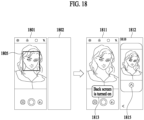
- the controller 1203 may further display predetermined content in the first area.
- the predetermined content may include, for example, a text "back screen is turned on.”
- the controller 1203 may further display the predetermined content in the second area.
- the content displayed in the second area may include a text "front screen is locked.” A related example will be described with reference to FIG. 15 .
- FIG. 13 is a flowchart illustrating a method of controlling a mobile terminal according to an example embodiment of the present disclosure. Operations illustrated in FIG. 13 may be performed in different orders or irrespective of an order depending on cases. Hereinafter, redundant descriptions, which have been made above will be omitted.
- a mobile terminal may acquire an image through a camera. Specifically, the mobile terminal may drive the camera based on an execution of an application related to the camera and acquire an image through the camera.
- the image acquired through the camera may be an image of an area located to face a lens of the camera. When a person is included in the area, the image may include a person image.
- At least a portion of a display of the mobile terminal may be located at a first side (e.g., a front side) of the mobile terminal and another portion may be located at a second side (e.g., a rear side) of the mobile terminal.
- the display may be implemented as a flexible display that is rolled at a side surface of the mobile terminal to be located at the first side and the second side.
- the mobile terminal may display the acquired image in a first area and a second area.
- the first area may correspond to one area of the display located at the first side.
- the second area may correspond to one area of the display located at the second side.
- the first area may be larger than the second area.
- the image may be provided in a size appropriate for each area.
- a control icon of the application related to the camera may be displayed.
- a portion of the control icon displayed in the first area may be displayed and, in some cases, the control icon may not be displayed.
- the image displayed in the first area and the second area may be an image acquired through the camera in real time.
- an image corresponding to the input may be stored in the mobile terminal as a picture.
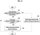
- FIG. 14 illustrates one operation of a method of controlling a mobile terminal in detail according to an example embodiment of the present disclosure.
- FIG. 14 illustrates operation 1301 of FIG. 13 in detail.
- the mobile terminal may verify whether information sensed through a sensor corresponds to a first condition.
- the sensor may include at least one sensor included in the mobile terminal.
- the sensor may include, for example, a pose sensor.
- a variety of known sensors may be used as the pose sensor, which is easy for those skilled in the art, and thus, a detailed description will be omitted.
- the information sensed through the sensor may include, for example, a sensor-sensed value.
- the sensor-sensed value may be represented by a number, but is not limited thereto.
- the mobile terminal may display the image acquired through the camera in the first area and the second area in operation 1402.
- the mobile terminal may display the image acquired through the camera in the first area and the second area.
- the predetermined information may include, for example, information indicating that a specific input is applied or information indicating that a pose of the mobile terminal corresponds to a predetermined pose, but is not limited thereto.
- the mobile terminal may display the image acquired through the camera in the first area and the second area.
- the first input may include, for example, an input applied to a first position (e.g., at least a portion of the first area) of the mobile terminal, an input of a specific type (e.g., a swipe input and a knock-on input), or an input in a specific form (e.g., a double-tap input, a long-press input, an input of moving in a predetermined direction).
- the mobile terminal may display the image acquired through the camera in the first area and the second area.
- a user of the mobile terminal and a model corresponding to a target for shooting may confirm the image.
- the model may actively use the camera, for example, change a pose while viewing the image.
- the user of the mobile terminal may smoothly perform communication about an appearance represented in the image. As such, a usability of the camera may be increased.
- the mobile terminal may verify whether the sensed information corresponds to the second condition in operation 1403.
- the second condition may be a condition differing from the aforementioned first condition.
- the second condition may include, for example, a case in which information sensed through the sensor does not correspond to predetermined information.
- the second condition may include a case in which the mobile terminal is at a pose turned 180° or a case in which an angle between a horizontal plane and a plane corresponding to the second area is less than or equal to a predetermined angle.
- the mobile terminal may display the image acquired through the camera in the second area in operation 1404.
- the displaying of the image in the first area may be omitted (or temporarily suspended).
- input sensing e.g., touch input sensing
- the mobile terminal may display the image acquired through the camera in the second area in operation 1404.
- a case in which the second condition is satisfied may be a case in which the user of the mobile terminal is to take a selfie using a camera mounted on the second side.
- the input sensing or the image display in the first area may be restricted while an image is displayed in the second area.
- the touch input sensing may be actively changed in response to a change of a gripping method of the mobile terminal so an unintended touch input is prevented, which may prevent a false operation.
- the third screen 1511 may be displayed in the first area and the fourth screen 1512 may be displayed in the second area.
- the first condition may include a case in which a presence of an object facing the second side is sensed.
- the first condition may include a case in which a touch input to the first icon 1505 is sensed in the mobile terminal.
- the first condition is not limited to the aforementioned example and may include a variety of conditions determined in advance.
- the third screen 1511 may be a screen including first content 1515 in addition to the first screen 1501.
- the first content 1515 may be content indicating that the fourth screen 1512 is displayed in the second area and include a text "back screen is turned on" as illustrated.
- a user viewing the first side e.g., the front side
- the fourth screen 1512 may include a second icon 1517 for providing a control icon and the image acquired through the camera.
- the control icon may be displayed in response to an input to the second icon 1517.
- a control icon 1525 may be displayed or provided.
- the control icon 1525 provided in response to the input to the second icon 1517 may be a portion of the control icon provided through the first screen 1501.
- a fifth screen 1521 may be displayed in the first area and a sixth screen 1522 may be displayed in the second area.
- the second condition may include a case in which a pose of the mobile terminal corresponds to a predetermined pose.
- the second condition may include a case in which a specific touch input (e.g., a swipe input in the first direction) is sensed in the mobile terminal.
- the second condition is not limited to the aforementioned example and may include a variety of conditions differing from the first condition.
- the fifth screen 1521 may be a screen with providing at least some restricted functions of the camera app.
- the fifth screen 1521 may be a screen in a state in which touch input sensing for the camera app through the fifth screen 1521 is restricted.
- the displaying of the control icon or the image acquired through the camera may be omitted (or suspended) and specific content may be displayed.
- the specific content may include a text "can use camera on back screen" as illustrated, but is not limited thereto.
- the sixth screen 1522 may include the control icon 1523 and the image acquired through the camera.
- the sixth screen 1522 may further include specific content as illustrated.
- the specific content may include, for example, a text "front screen is locked" but is not limited thereto.
- FIG. 16 illustrates another example of a screen displayed on mobile terminal according to an example embodiment of the present disclosure. Specifically, FIG. 16 illustrates a case in which an image acquired through a camera is displayed in a first area and a second area based on a user input, or an image acquired through a camera is displayed in the second area.
- a first screen 1601 may be displayed in a first area on a first side (e.g., a front side) of a mobile terminal and a second screen 1602 may be displayed in a second area on a second side (e.g., a rear side) of the mobile terminal.
- a first side e.g., a front side
- a second screen 1602 may be displayed in a second area on a second side (e.g., a rear side) of the mobile terminal.
- the icons for controlling the screen display may be displayed in a specific area 1603.
- the icons for controlling the screen display may be displayed on the first screen 1601 in response to a specific input being applied.
- the first icon 1605 may include an icon that instructs a screen to be displayed in the first area and the screen display to be omitted in the second area.
- the second icon 1607 may include an icon that instructs a screen to be displayed in each of the first area and the second area.
- the third icon 1609 may include an icon that instructs the screen display to be omitted in the first area and a screen to be displayed in the second area.
- the first screen 1601 and the second screen 1602 may be displayed on the mobile terminal. Specifically, when an input is applied to the first icon 1605, the first screen 1601 may be displayed in the first area of the mobile terminal and the second screen 1602 may be displayed in the second area.
- a third screen 1611 and a fourth screen 1612 may be displayed on the mobile terminal.
- the third screen 1611 may be displayed in the first area of the mobile terminal and the fourth screen 1612 may be displayed in the second area. Since the third screen 1611 may correspond to the third screen 1511 of FIG. 15 and the fourth screen 1612 may correspond to the fourth screen 1512 of FIG. 15 , a detailed description will be omitted.
- a fifth screen 1621 and a sixth screen 1622 may be displayed on the mobile terminal.
- the fifth screen 1621 may be displayed in the first area of the mobile terminal and the sixth screen 1622 may be displayed in the second area. Since the fifth screen 1621 may correspond to the fifth screen 1521 of FIG. 15 and the sixth screen 1622 may correspond to the sixth screen 1522 of FIG. 15 , a detailed description will be omitted.
- FIG. 17 illustrates another example of a screen displayed on a mobile terminal according to an example embodiment of the present disclosure. Specifically, FIG. 17 illustrates a case in which displaying of an image acquired through a camera is controlled based on an input applied to the mobile terminal.
- a first screen 1701 may be displayed in a first area on a first side of the mobile terminal and a second screen 1702 may be displayed in a second area on a second side of the mobile terminal.
- the first screen 1701 and the second screen 1702 may be displayed in response to a camera application being executed or a specific input being applied.
- embodiments are not limited thereto and the first screen 1701 and the second screen 1702 may be displayed when a predetermined condition is satisfied.
- the first screen 1701 and the second screen 1702 may be a screen with providing some restricted functions of the mobile terminal.
- the first screen 1701 and the second screen 1702 may be screens displayed in a state in which a function of the camera app is restricted. In this example, acquiring of an image through a camera or controlling of the camera may be suspended.
- the first screen 1701 may be an overlapping screen appearing on the first screen 1501 of FIG. 15 at a first transparency.
- the second screen 1702 may be an overlapping screen appearing on the second screen 1502, the fourth screen 1512, or the sixth screen 1522 of FIG. 15 at the first transparency.
- the first transparency may correspond to a predetermined value.
- the restricted function may be activated when a specific input is applied in a state in which the first screen 1701 and the second screen 1702 are displayed.
- the specific input may include, for example, a first input 1703 or a second input 1705.
- the first input 1703 may be an input applied to at least a portion of the first area.
- the second input 1705 may be an input applied to at least a portion of the second area.
- the first input 1703 may be a swipe input to the first area and the second input 1705 may be a swipe input to the second area.
- the first input 1703 may be a swipe input applied to the first area in a first direction and the second input 1705 may be a swipe input applied to the second area in the first direction.
- first input 1703 may be a swipe input applied to the first area in the first direction and the second input 1705 may be a swipe input applied to the second area in a second direction.
- Types of the first input 1703 and the second input 1705 are not limited to the aforementioned examples and thus, may be implemented in various forms.
- the first screen 1701 and the second screen 1702 may each provide content indicating that at least a portion of functions are restricted. For example, as illustrated, a text "to use both front and rear cameras, slide here to unlock” may be displayed on the first screen 1701. Also, a text “slide screen to unlock” may be displayed on the second screen 1702. However, embodiments are not limited thereto and, on the first screen 1701 or the second screen 1702, additional content (e.g., content indicating "can use camera on back screen”) may be further displayed or some contents may be omitted.
- additional content e.g., content indicating "can use camera on back screen
- FIGS. 18 and 19 illustrate a method of controlling a mobile terminal based on an image acquired by the mobile terminal according to an example embodiment of the present disclosure. Specifically, FIG. 18 illustrates a method of displaying an image based on whether a person image is included and FIG. 19 illustrates a method of displaying an image based on a proportion occupied by a person in a person image.
- a mobile terminal may acquire an image through a camera and display the acquired image through a first screen 1801 in a first area of a first side of the mobile terminal. Based on the displaying on the first screen 1801, the mobile terminal may display a second screen 1802 in a second area on a second side of the mobile terminal.
- the first screen 1801 may correspond to the first screen 1501 of FIG. 15 and the second screen 1802 may correspond to the second screen 1502 of FIG. 15 .
- the mobile terminal may verify whether the person image 1805 is included in the image acquired through the camera. For example, the mobile terminal may verify whether a feature point corresponding to the person image 1805 is included in an acquired image and verify whether the person image 1805 is included in the acquired image based on a verification result.
- the mobile terminal may display a first screen 1901 in the first area and display a second screen 1902 in the second area.
- the first screen 1901 may include an image 1905 acquired through the camera.
- the second screen 1902 may include a locked screen or an inactivated screen.
- FIG. 20 illustrates a method of controlling a mobile terminal based on an input applied to the mobile terminal according to an example embodiment of the present disclosure.
- a first screen 2001 including an image acquired through a camera and a control icon of a camera app may be displayed on a first side (e.g., a front side) of a mobile terminal in response to the camera app being executed.
- a user may use the mobile terminal by gripping the mobile terminal with a hand 2005.
- a touch input may be applied by the user to the first side (e.g., the front side) and a second side (e.g., a rear side) of the mobile terminal.
- touch inputs may be applied to lower portions of the first side and the second side of the mobile terminal.
- touch inputs may be applied to upper portions of the first side and the second side of the mobile terminal.
- a position (or area) in which the image 2007 is displayed may be designated for each position of the touch input in advance. For example, when a position of the touch input corresponds to a first position, a position in which the image 2007 is displayed may correspond to a second position.
- the mobile terminal may restrict (or deactivate) touch input sensing for the identified position. Through this, a situation in which a touch input is unintentionally applied may be prevented so a false operation of the mobile terminal is prevented.
- FIG. 21 illustrates a mobile terminal according to an example embodiment of the present disclosure. Specifically, FIG. 21 is a diagram for explaining an embodiment of the present disclosure applied in a case in which a mobile terminal is of an out-folding type.
- a mobile terminal may be folded such that a display is exposed externally.
- the display may be divided into one area and another area based on a rotation axis for folding the display.
- the one area may correspond to a first area and the other area may correspond to a second area.
- a first screen 2101 may be displayed in the first area and a second screen 2102 may be displayed in the second area.
- the mobile terminal may display a screen including a portion of control icons displayed on the first side, on the second side based on the size of the second side.
- the mobile terminal may display a portion of all icons provided by applications (e.g., a camera app) on the second side.
- the mobile terminal may display a screen including at least a portion of the image acquired through the camera, on the second side based on the size of the second side.
- the mobile terminal may provide images representing various filter-applied examples below the acquired image. If an input is applied to an icon 2305 instructing to change a layout, the mobile terminal may display the images of various filter-applied examples by enlarging the images as shown in the sixth screen 2302.
- an image may be provided in each of a first area and a second area so that an image acquired through a camera is viewed by both user of the mobile terminal performing the image capturing and model to be captured.
- communication between the user of the mobile terminal and the model to be captured may be smoothly performed.
- the image capturing may be easily performed, which may lead to an improvement in usability of the mobile terminal.
- a situation in which the user of the mobile terminal views a second side may be verified based on a sensed pose of the mobile terminal.
- a screen may be provided on the second side based on the verified situation, so that the user can more easily use the mobile terminal.
Landscapes
- Engineering & Computer Science (AREA)
- Theoretical Computer Science (AREA)
- Physics & Mathematics (AREA)
- General Engineering & Computer Science (AREA)
- Computer Hardware Design (AREA)
- Human Computer Interaction (AREA)
- General Physics & Mathematics (AREA)
- Signal Processing (AREA)
- Mathematical Physics (AREA)
- Computer Networks & Wireless Communication (AREA)
- Telephone Set Structure (AREA)
Applications Claiming Priority (1)
| Application Number | Priority Date | Filing Date | Title |
|---|---|---|---|
| PCT/KR2020/004404 WO2021201315A1 (ko) | 2020-03-31 | 2020-03-31 | 이미지를 표시하는 이동 단말기 및 그 제어 방법 |
Publications (3)
| Publication Number | Publication Date |
|---|---|
| EP4131909A1 true EP4131909A1 (de) | 2023-02-08 |
| EP4131909A4 EP4131909A4 (de) | 2023-12-27 |
| EP4131909B1 EP4131909B1 (de) | 2024-12-18 |
Family
ID=77855927
Family Applications (1)
| Application Number | Title | Priority Date | Filing Date |
|---|---|---|---|
| EP20929224.2A Active EP4131909B1 (de) | 2020-03-31 | 2020-03-31 | Mobiles endgerät zur anzeige eines bildes und steuerungsverfahren dafür |
Country Status (4)
| Country | Link |
|---|---|
| US (1) | US11625067B2 (de) |
| EP (1) | EP4131909B1 (de) |
| KR (1) | KR102711123B1 (de) |
| WO (1) | WO2021201315A1 (de) |
Families Citing this family (21)
| Publication number | Priority date | Publication date | Assignee | Title |
|---|---|---|---|---|
| USD975044S1 (en) * | 2020-02-24 | 2023-01-10 | Lg Electronics Inc. | Mobile phone |
| USD966247S1 (en) * | 2020-03-31 | 2022-10-11 | Lg Electronics Inc. | Mobile phone |
| USD966246S1 (en) * | 2020-03-31 | 2022-10-11 | Lg Electronics Inc. | Mobile phone |
| USD966248S1 (en) * | 2020-03-31 | 2022-10-11 | Lg Electronics Inc. | Mobile phone |
| USD977468S1 (en) * | 2020-03-31 | 2023-02-07 | Lg Electronics Inc. | Mobile phone |
| USD1001788S1 (en) * | 2020-04-02 | 2023-10-17 | Lg Electronics Inc. | Mobile phone |
| USD989055S1 (en) * | 2020-04-02 | 2023-06-13 | Lg Electronics Inc. | Mobile phone |
| USD978849S1 (en) * | 2020-04-06 | 2023-02-21 | Lg Electronics Inc. | Mobile phone |
| USD981996S1 (en) * | 2020-04-06 | 2023-03-28 | Lg Electronics Inc. | Mobile phone |
| USD981997S1 (en) * | 2020-04-06 | 2023-03-28 | Lg Electronics Inc. | Mobile phone |
| USD978848S1 (en) * | 2020-04-06 | 2023-02-21 | Lg Electronics Inc. | Mobile phone |
| USD981384S1 (en) * | 2020-04-06 | 2023-03-21 | Lg Electronics Inc. | Mobile phone |
| USD978123S1 (en) * | 2020-04-06 | 2023-02-14 | Lg Electronics Inc. | Mobile phone |
| USD974343S1 (en) * | 2020-04-06 | 2023-01-03 | Lg Electronics Inc. | Mobile phone |
| USD986846S1 (en) * | 2020-05-18 | 2023-05-23 | Lg Electronics Inc. | Mobile phone |
| CN111627340B (zh) * | 2020-06-30 | 2023-05-05 | 京东方科技集团股份有限公司 | 显示装置及电子设备 |
| CN116348942A (zh) * | 2020-10-12 | 2023-06-27 | 三星电子株式会社 | 包括柔性显示器的电子装置 |
| WO2022114848A1 (ko) | 2020-11-30 | 2022-06-02 | 삼성전자 주식회사 | 플렉서블 전자 장치 및 카메라 뷰 화면 운용 방법 |
| WO2022110117A1 (zh) * | 2020-11-30 | 2022-06-02 | 京东方科技集团股份有限公司 | 显示面板及其驱动方法、显示装置 |
| US11907516B2 (en) * | 2022-04-16 | 2024-02-20 | Samsung Electronics Co., Ltd. | Electronic device, method, and non-transitory computer readable storage medium for identifying set of information according to change in size of display area of flexible display |
| US12100323B1 (en) * | 2023-07-24 | 2024-09-24 | Motorola Mobility Llc | Managing concurrent use of front and back portions of an adaptive rollable display device based on imaging user(s) |
Family Cites Families (10)
| Publication number | Priority date | Publication date | Assignee | Title |
|---|---|---|---|---|
| CN103477304A (zh) * | 2011-02-10 | 2013-12-25 | 三星电子株式会社 | 包含触摸屏显示器的便携式设备以及控制它的方法 |
| KR102105958B1 (ko) | 2013-03-04 | 2020-04-29 | 엘지전자 주식회사 | 익스펜더블 디스플레이를 탑재한 포터블 디바이스의 2중 잠금 해제 장치 및 그 방법 |
| KR102131825B1 (ko) * | 2013-03-20 | 2020-07-09 | 엘지전자 주식회사 | 적응적 터치 센서티브 영역을 제공하는 폴더블 디스플레이 디바이스 및 그 제어 방법 |
| KR101752750B1 (ko) * | 2015-05-28 | 2017-07-11 | 한국과학기술연구원 | 확장 가능한 디스플레이를 갖는 디스플레이 장치, 그 제어 방법 및 그 방법을 수행하기 위한 기록 매체 |
| KR102415655B1 (ko) * | 2015-07-07 | 2022-07-04 | 엘지전자 주식회사 | 이동 단말기 |
| KR20170062121A (ko) * | 2015-11-27 | 2017-06-07 | 엘지전자 주식회사 | 이동단말기 및 그 제어방법 |
| KR102433269B1 (ko) | 2016-01-18 | 2022-08-17 | 삼성전자 주식회사 | 플렉서블 디스플레이 장치 및 디스플레이 제어 방법 |
| KR102480462B1 (ko) * | 2016-02-05 | 2022-12-23 | 삼성전자주식회사 | 복수의 디스플레이들을 포함하는 전자 장치 및 그 동작 방법 |
| KR102417002B1 (ko) * | 2017-06-28 | 2022-07-05 | 삼성전자 주식회사 | 두 개의 디스플레이를 구비하는 전자 장치 및 이의 화면 운용 방법 |
| KR102266152B1 (ko) * | 2018-02-22 | 2021-06-17 | 삼성전자주식회사 | 디스플레이 영역의 크기 변경이 가능한 플렉시블 디스플레이를 포함하는 전자 장치 및 그 제어 방법 |
-
2020
- 2020-03-31 EP EP20929224.2A patent/EP4131909B1/de active Active
- 2020-03-31 KR KR1020227033392A patent/KR102711123B1/ko active Active
- 2020-03-31 WO PCT/KR2020/004404 patent/WO2021201315A1/ko not_active Ceased
- 2020-07-23 US US16/937,341 patent/US11625067B2/en active Active
Also Published As
| Publication number | Publication date |
|---|---|
| US20210303027A1 (en) | 2021-09-30 |
| US11625067B2 (en) | 2023-04-11 |
| WO2021201315A1 (ko) | 2021-10-07 |
| KR102711123B1 (ko) | 2024-09-30 |
| EP4131909B1 (de) | 2024-12-18 |
| KR20220151174A (ko) | 2022-11-14 |
| EP4131909A4 (de) | 2023-12-27 |
Similar Documents
| Publication | Publication Date | Title |
|---|---|---|
| US11625067B2 (en) | Mobile terminal for displaying image and control method thereof | |
| US11169704B1 (en) | Mobile terminal for displaying content on flexible display and control method thereof | |
| US12200350B2 (en) | Image display device and method for controlling same | |
| KR102905075B1 (ko) | 이동 단말기 | |
| US11709594B2 (en) | Mobile terminal and control method therefor | |
| EP3940522B1 (de) | Mobiles endgerät | |
| EP3923114A1 (de) | Mobiles endgerät und steuerungsverfahren dafür | |
| EP3905021A1 (de) | Mobiles endgerät und steuerungsverfahren dafür | |
| US10506153B2 (en) | Device and method for processing image in electronic device | |
| EP3116215B1 (de) | Tragbares endgerät und verfahren zur steuerung davon | |
| EP4058868B1 (de) | Walzgesten und verhinderung von fehlberührungen an walzvorrichtungen | |
| KR102902110B1 (ko) | 이동 단말기 | |
| CN104049851B (zh) | 一种控制方法、装置和电子设备 | |
| US11756507B2 (en) | Mobile terminal for displaying content and control method thereof | |
| CN105159405A (zh) | 信息处理方法及电子设备 | |
| KR20140109722A (ko) | 이동 단말기 | |
| WO2015053188A1 (ja) | 表示装置及び画像変形方法 | |
| US11606502B2 (en) | Mobile terminal for capturing image and control method thereof | |
| KR20230051255A (ko) | 이동 단말기 및 그 제어 방법 | |
| EP3916533B1 (de) | Mobiles endgerät und steuerungsverfahren dafür | |
| CN113741778B (zh) | 设备控制方法、装置、存储介质及电子设备 | |
| US12386502B2 (en) | Application management apparatus and controlling method therefor | |
| KR101530517B1 (ko) | 촬영 기능을 수행하는 사용자 단말기 및 사용자 단말기의 촬영 아이콘 위치 조정 방법 | |
| KR20190074036A (ko) | 후면에 지문인식센서를 구비한 스마트폰의 제어방법 | |
| JP2017138889A (ja) | 携帯端末、制御方法、およびプログラム |
Legal Events
| Date | Code | Title | Description |
|---|---|---|---|
| STAA | Information on the status of an ep patent application or granted ep patent |
Free format text: STATUS: THE INTERNATIONAL PUBLICATION HAS BEEN MADE |
|
| PUAI | Public reference made under article 153(3) epc to a published international application that has entered the european phase |
Free format text: ORIGINAL CODE: 0009012 |
|
| STAA | Information on the status of an ep patent application or granted ep patent |
Free format text: STATUS: REQUEST FOR EXAMINATION WAS MADE |
|
| 17P | Request for examination filed |
Effective date: 20221031 |
|
| AK | Designated contracting states |
Kind code of ref document: A1 Designated state(s): AL AT BE BG CH CY CZ DE DK EE ES FI FR GB GR HR HU IE IS IT LI LT LU LV MC MK MT NL NO PL PT RO RS SE SI SK SM TR |
|
| DAV | Request for validation of the european patent (deleted) | ||
| DAX | Request for extension of the european patent (deleted) | ||
| A4 | Supplementary search report drawn up and despatched |
Effective date: 20231129 |
|
| RIC1 | Information provided on ipc code assigned before grant |
Ipc: G06F 1/16 20060101ALI20231123BHEP Ipc: H04M 1/72403 20210101ALI20231123BHEP Ipc: H04M 1/02 20060101ALI20231123BHEP Ipc: H04M 1/725 20210101AFI20231123BHEP |
|
| GRAP | Despatch of communication of intention to grant a patent |
Free format text: ORIGINAL CODE: EPIDOSNIGR1 |
|
| STAA | Information on the status of an ep patent application or granted ep patent |
Free format text: STATUS: GRANT OF PATENT IS INTENDED |
|
| RIC1 | Information provided on ipc code assigned before grant |
Ipc: G06F 1/16 20060101ALI20240628BHEP Ipc: H04M 1/72403 20210101ALI20240628BHEP Ipc: H04M 1/02 20060101ALI20240628BHEP Ipc: H04M 1/725 20210101AFI20240628BHEP |
|
| INTG | Intention to grant announced |
Effective date: 20240710 |
|
| GRAS | Grant fee paid |
Free format text: ORIGINAL CODE: EPIDOSNIGR3 |
|
| GRAA | (expected) grant |
Free format text: ORIGINAL CODE: 0009210 |
|
| STAA | Information on the status of an ep patent application or granted ep patent |
Free format text: STATUS: THE PATENT HAS BEEN GRANTED |
|
| AK | Designated contracting states |
Kind code of ref document: B1 Designated state(s): AL AT BE BG CH CY CZ DE DK EE ES FI FR GB GR HR HU IE IS IT LI LT LU LV MC MK MT NL NO PL PT RO RS SE SI SK SM TR |
|
| REG | Reference to a national code |
Ref country code: CH Ref legal event code: EP |
|
| REG | Reference to a national code |
Ref country code: DE Ref legal event code: R096 Ref document number: 602020043542 Country of ref document: DE |
|
| REG | Reference to a national code |
Ref country code: IE Ref legal event code: FG4D |
|
| REG | Reference to a national code |
Ref country code: LT Ref legal event code: MG9D |
|
| PG25 | Lapsed in a contracting state [announced via postgrant information from national office to epo] |
Ref country code: HR Free format text: LAPSE BECAUSE OF FAILURE TO SUBMIT A TRANSLATION OF THE DESCRIPTION OR TO PAY THE FEE WITHIN THE PRESCRIBED TIME-LIMIT Effective date: 20241218 |
|
| PG25 | Lapsed in a contracting state [announced via postgrant information from national office to epo] |
Ref country code: FI Free format text: LAPSE BECAUSE OF FAILURE TO SUBMIT A TRANSLATION OF THE DESCRIPTION OR TO PAY THE FEE WITHIN THE PRESCRIBED TIME-LIMIT Effective date: 20241218 |
|
| PG25 | Lapsed in a contracting state [announced via postgrant information from national office to epo] |
Ref country code: BG Free format text: LAPSE BECAUSE OF FAILURE TO SUBMIT A TRANSLATION OF THE DESCRIPTION OR TO PAY THE FEE WITHIN THE PRESCRIBED TIME-LIMIT Effective date: 20241218 |
|
| PG25 | Lapsed in a contracting state [announced via postgrant information from national office to epo] |
Ref country code: NO Free format text: LAPSE BECAUSE OF FAILURE TO SUBMIT A TRANSLATION OF THE DESCRIPTION OR TO PAY THE FEE WITHIN THE PRESCRIBED TIME-LIMIT Effective date: 20250318 |
|
| REG | Reference to a national code |
Ref country code: NL Ref legal event code: MP Effective date: 20241218 |
|
| PG25 | Lapsed in a contracting state [announced via postgrant information from national office to epo] |
Ref country code: GR Free format text: LAPSE BECAUSE OF FAILURE TO SUBMIT A TRANSLATION OF THE DESCRIPTION OR TO PAY THE FEE WITHIN THE PRESCRIBED TIME-LIMIT Effective date: 20250319 Ref country code: LV Free format text: LAPSE BECAUSE OF FAILURE TO SUBMIT A TRANSLATION OF THE DESCRIPTION OR TO PAY THE FEE WITHIN THE PRESCRIBED TIME-LIMIT Effective date: 20241218 |
|
| PG25 | Lapsed in a contracting state [announced via postgrant information from national office to epo] |
Ref country code: RS Free format text: LAPSE BECAUSE OF FAILURE TO SUBMIT A TRANSLATION OF THE DESCRIPTION OR TO PAY THE FEE WITHIN THE PRESCRIBED TIME-LIMIT Effective date: 20250318 |
|
| PG25 | Lapsed in a contracting state [announced via postgrant information from national office to epo] |
Ref country code: NL Free format text: LAPSE BECAUSE OF FAILURE TO SUBMIT A TRANSLATION OF THE DESCRIPTION OR TO PAY THE FEE WITHIN THE PRESCRIBED TIME-LIMIT Effective date: 20241218 |
|
| REG | Reference to a national code |
Ref country code: AT Ref legal event code: MK05 Ref document number: 1753191 Country of ref document: AT Kind code of ref document: T Effective date: 20241218 |
|
| PG25 | Lapsed in a contracting state [announced via postgrant information from national office to epo] |
Ref country code: SM Free format text: LAPSE BECAUSE OF FAILURE TO SUBMIT A TRANSLATION OF THE DESCRIPTION OR TO PAY THE FEE WITHIN THE PRESCRIBED TIME-LIMIT Effective date: 20241218 |
|
| PG25 | Lapsed in a contracting state [announced via postgrant information from national office to epo] |
Ref country code: PL Free format text: LAPSE BECAUSE OF FAILURE TO SUBMIT A TRANSLATION OF THE DESCRIPTION OR TO PAY THE FEE WITHIN THE PRESCRIBED TIME-LIMIT Effective date: 20241218 |
|
| PG25 | Lapsed in a contracting state [announced via postgrant information from national office to epo] |
Ref country code: ES Free format text: LAPSE BECAUSE OF FAILURE TO SUBMIT A TRANSLATION OF THE DESCRIPTION OR TO PAY THE FEE WITHIN THE PRESCRIBED TIME-LIMIT Effective date: 20241218 |
|
| PG25 | Lapsed in a contracting state [announced via postgrant information from national office to epo] |
Ref country code: IS Free format text: LAPSE BECAUSE OF FAILURE TO SUBMIT A TRANSLATION OF THE DESCRIPTION OR TO PAY THE FEE WITHIN THE PRESCRIBED TIME-LIMIT Effective date: 20250418 |
|
| PG25 | Lapsed in a contracting state [announced via postgrant information from national office to epo] |
Ref country code: PT Free format text: LAPSE BECAUSE OF FAILURE TO SUBMIT A TRANSLATION OF THE DESCRIPTION OR TO PAY THE FEE WITHIN THE PRESCRIBED TIME-LIMIT Effective date: 20250421 |
|
| PG25 | Lapsed in a contracting state [announced via postgrant information from national office to epo] |
Ref country code: EE Free format text: LAPSE BECAUSE OF FAILURE TO SUBMIT A TRANSLATION OF THE DESCRIPTION OR TO PAY THE FEE WITHIN THE PRESCRIBED TIME-LIMIT Effective date: 20241218 |
|
| PG25 | Lapsed in a contracting state [announced via postgrant information from national office to epo] |
Ref country code: RO Free format text: LAPSE BECAUSE OF FAILURE TO SUBMIT A TRANSLATION OF THE DESCRIPTION OR TO PAY THE FEE WITHIN THE PRESCRIBED TIME-LIMIT Effective date: 20241218 Ref country code: AT Free format text: LAPSE BECAUSE OF FAILURE TO SUBMIT A TRANSLATION OF THE DESCRIPTION OR TO PAY THE FEE WITHIN THE PRESCRIBED TIME-LIMIT Effective date: 20241218 |
|
| PG25 | Lapsed in a contracting state [announced via postgrant information from national office to epo] |
Ref country code: SK Free format text: LAPSE BECAUSE OF FAILURE TO SUBMIT A TRANSLATION OF THE DESCRIPTION OR TO PAY THE FEE WITHIN THE PRESCRIBED TIME-LIMIT Effective date: 20241218 |
|
| PG25 | Lapsed in a contracting state [announced via postgrant information from national office to epo] |
Ref country code: CZ Free format text: LAPSE BECAUSE OF FAILURE TO SUBMIT A TRANSLATION OF THE DESCRIPTION OR TO PAY THE FEE WITHIN THE PRESCRIBED TIME-LIMIT Effective date: 20241218 |
|
| PG25 | Lapsed in a contracting state [announced via postgrant information from national office to epo] |
Ref country code: IT Free format text: LAPSE BECAUSE OF FAILURE TO SUBMIT A TRANSLATION OF THE DESCRIPTION OR TO PAY THE FEE WITHIN THE PRESCRIBED TIME-LIMIT Effective date: 20241218 |
|
| PG25 | Lapsed in a contracting state [announced via postgrant information from national office to epo] |
Ref country code: SE Free format text: LAPSE BECAUSE OF FAILURE TO SUBMIT A TRANSLATION OF THE DESCRIPTION OR TO PAY THE FEE WITHIN THE PRESCRIBED TIME-LIMIT Effective date: 20241218 |
|
| REG | Reference to a national code |
Ref country code: DE Ref legal event code: R097 Ref document number: 602020043542 Country of ref document: DE |
|
| PG25 | Lapsed in a contracting state [announced via postgrant information from national office to epo] |
Ref country code: DK Free format text: LAPSE BECAUSE OF FAILURE TO SUBMIT A TRANSLATION OF THE DESCRIPTION OR TO PAY THE FEE WITHIN THE PRESCRIBED TIME-LIMIT Effective date: 20241218 |
|
| PG25 | Lapsed in a contracting state [announced via postgrant information from national office to epo] |
Ref country code: MC Free format text: LAPSE BECAUSE OF FAILURE TO SUBMIT A TRANSLATION OF THE DESCRIPTION OR TO PAY THE FEE WITHIN THE PRESCRIBED TIME-LIMIT Effective date: 20241218 |
|
| PLBE | No opposition filed within time limit |
Free format text: ORIGINAL CODE: 0009261 |
|
| REG | Reference to a national code |
Ref country code: CH Ref legal event code: H13 Free format text: ST27 STATUS EVENT CODE: U-0-0-H10-H13 (AS PROVIDED BY THE NATIONAL OFFICE) Effective date: 20251024 |
|
| STAA | Information on the status of an ep patent application or granted ep patent |
Free format text: STATUS: NO OPPOSITION FILED WITHIN TIME LIMIT |
|
| PG25 | Lapsed in a contracting state [announced via postgrant information from national office to epo] |
Ref country code: LU Free format text: LAPSE BECAUSE OF NON-PAYMENT OF DUE FEES Effective date: 20250331 |
|
| 26N | No opposition filed |
Effective date: 20250919 |
|
| GBPC | Gb: european patent ceased through non-payment of renewal fee |
Effective date: 20250331 |
|
| REG | Reference to a national code |
Ref country code: BE Ref legal event code: MM Effective date: 20250331 |
|
| PG25 | Lapsed in a contracting state [announced via postgrant information from national office to epo] |
Ref country code: GB Free format text: LAPSE BECAUSE OF NON-PAYMENT OF DUE FEES Effective date: 20250331 |
|
| PG25 | Lapsed in a contracting state [announced via postgrant information from national office to epo] |
Ref country code: BE Free format text: LAPSE BECAUSE OF NON-PAYMENT OF DUE FEES Effective date: 20250331 |
|
| PG25 | Lapsed in a contracting state [announced via postgrant information from national office to epo] |
Ref country code: CH Free format text: LAPSE BECAUSE OF NON-PAYMENT OF DUE FEES Effective date: 20250331 |
|
| PG25 | Lapsed in a contracting state [announced via postgrant information from national office to epo] |
Ref country code: IE Free format text: LAPSE BECAUSE OF NON-PAYMENT OF DUE FEES Effective date: 20250331 |
|
| PGFP | Annual fee paid to national office [announced via postgrant information from national office to epo] |
Ref country code: DE Payment date: 20260205 Year of fee payment: 7 |
|
| PGFP | Annual fee paid to national office [announced via postgrant information from national office to epo] |
Ref country code: FR Payment date: 20260209 Year of fee payment: 7 |