EP4131916A1 - Kamera und bilderfassungsverfahren - Google Patents
Kamera und bilderfassungsverfahren Download PDFInfo
- Publication number
- EP4131916A1 EP4131916A1 EP20933350.9A EP20933350A EP4131916A1 EP 4131916 A1 EP4131916 A1 EP 4131916A1 EP 20933350 A EP20933350 A EP 20933350A EP 4131916 A1 EP4131916 A1 EP 4131916A1
- Authority
- EP
- European Patent Office
- Prior art keywords
- light beam
- image
- channel
- brightness adjustment
- adjustment parameter
- Prior art date
- Legal status (The legal status is an assumption and is not a legal conclusion. Google has not performed a legal analysis and makes no representation as to the accuracy of the status listed.)
- Pending
Links
- 238000000034 method Methods 0.000 title claims abstract description 43
- 230000003287 optical effect Effects 0.000 claims abstract description 81
- 238000006243 chemical reaction Methods 0.000 claims description 57
- 238000007499 fusion processing Methods 0.000 claims description 25
- 239000012528 membrane Substances 0.000 claims description 25
- 238000001914 filtration Methods 0.000 claims description 6
- 238000012545 processing Methods 0.000 description 34
- 230000008569 process Effects 0.000 description 21
- 230000004927 fusion Effects 0.000 description 15
- 230000004044 response Effects 0.000 description 15
- 238000010586 diagram Methods 0.000 description 11
- 230000008859 change Effects 0.000 description 6
- 238000005516 engineering process Methods 0.000 description 6
- 239000013589 supplement Substances 0.000 description 6
- 239000003086 colorant Substances 0.000 description 5
- 230000000694 effects Effects 0.000 description 5
- 238000003384 imaging method Methods 0.000 description 5
- 238000004519 manufacturing process Methods 0.000 description 4
- 238000004590 computer program Methods 0.000 description 3
- 230000003321 amplification Effects 0.000 description 2
- 238000004458 analytical method Methods 0.000 description 2
- 238000003491 array Methods 0.000 description 2
- 238000004364 calculation method Methods 0.000 description 2
- 230000006872 improvement Effects 0.000 description 2
- 239000000463 material Substances 0.000 description 2
- 238000003199 nucleic acid amplification method Methods 0.000 description 2
- 230000005540 biological transmission Effects 0.000 description 1
- 238000013500 data storage Methods 0.000 description 1
- 238000011161 development Methods 0.000 description 1
- 230000004048 modification Effects 0.000 description 1
- 238000012986 modification Methods 0.000 description 1
- 238000012544 monitoring process Methods 0.000 description 1
- 239000013307 optical fiber Substances 0.000 description 1
- 230000000644 propagated effect Effects 0.000 description 1
- 230000005855 radiation Effects 0.000 description 1
- 238000002310 reflectometry Methods 0.000 description 1
- 239000004065 semiconductor Substances 0.000 description 1
- 239000007787 solid Substances 0.000 description 1
- 230000009469 supplementation Effects 0.000 description 1
- 230000001629 suppression Effects 0.000 description 1
- 238000002834 transmittance Methods 0.000 description 1
Images



Classifications
-
- H—ELECTRICITY
- H04—ELECTRIC COMMUNICATION TECHNIQUE
- H04N—PICTORIAL COMMUNICATION, e.g. TELEVISION
- H04N9/00—Details of colour television systems
- H04N9/77—Circuits for processing the brightness signal and the chrominance signal relative to each other, e.g. adjusting the phase of the brightness signal relative to the colour signal, correcting differential gain or differential phase
-
- H—ELECTRICITY
- H04—ELECTRIC COMMUNICATION TECHNIQUE
- H04N—PICTORIAL COMMUNICATION, e.g. TELEVISION
- H04N23/00—Cameras or camera modules comprising electronic image sensors; Control thereof
- H04N23/10—Cameras or camera modules comprising electronic image sensors; Control thereof for generating image signals from different wavelengths
- H04N23/11—Cameras or camera modules comprising electronic image sensors; Control thereof for generating image signals from different wavelengths for generating image signals from visible and infrared light wavelengths
-
- H—ELECTRICITY
- H04—ELECTRIC COMMUNICATION TECHNIQUE
- H04N—PICTORIAL COMMUNICATION, e.g. TELEVISION
- H04N23/00—Cameras or camera modules comprising electronic image sensors; Control thereof
- H04N23/10—Cameras or camera modules comprising electronic image sensors; Control thereof for generating image signals from different wavelengths
- H04N23/12—Cameras or camera modules comprising electronic image sensors; Control thereof for generating image signals from different wavelengths with one sensor only
-
- H—ELECTRICITY
- H04—ELECTRIC COMMUNICATION TECHNIQUE
- H04N—PICTORIAL COMMUNICATION, e.g. TELEVISION
- H04N23/00—Cameras or camera modules comprising electronic image sensors; Control thereof
- H04N23/50—Constructional details
- H04N23/55—Optical parts specially adapted for electronic image sensors; Mounting thereof
-
- H—ELECTRICITY
- H04—ELECTRIC COMMUNICATION TECHNIQUE
- H04N—PICTORIAL COMMUNICATION, e.g. TELEVISION
- H04N23/00—Cameras or camera modules comprising electronic image sensors; Control thereof
- H04N23/70—Circuitry for compensating brightness variation in the scene
- H04N23/71—Circuitry for evaluating the brightness variation
-
- H—ELECTRICITY
- H04—ELECTRIC COMMUNICATION TECHNIQUE
- H04N—PICTORIAL COMMUNICATION, e.g. TELEVISION
- H04N5/00—Details of television systems
- H04N5/222—Studio circuitry; Studio devices; Studio equipment
- H04N5/262—Studio circuits, e.g. for mixing, switching-over, change of character of image, other special effects ; Cameras specially adapted for the electronic generation of special effects
- H04N5/265—Mixing
Definitions
- This application relates to the field of image shooting technologies, and in particular, to a camera and an image obtaining method.
- the apparatus includes a lens, a light-splitting prism, two image sensors, and an image signal processing (image signal processing, ISP) element.
- the two image sensors are respectively located on two sides of the light-splitting prism, and the two image sensors are perpendicular to each other.
- a light beam passes through the lens and arrives at the light-splitting prism, and the light-splitting prism divides the light beam into an infrared light beam and a visible light beam that are perpendicular to each other.
- One of the two image sensors is configured to receive the infrared light beam and perform photoelectric conversion, and the other is configured to receive the visible light beam and perform photoelectric conversion.
- the ISP element performs signal processing on electrical signals that are obtained through photoelectric conversion performed by the two image sensors, and then a fusion chip fuses two images processed by the ISP element into one image, so that a high-quality image is obtained.
- Embodiments of this application provide a camera and an image obtaining method, to reduce costs of shooting an image in a low-illuminance scenario and improve a yield rate.
- a camera includes an optical module, a single image sensor, and an image processor electrically connected to the image processor.
- the image sensor includes at least one first channel and at least one second channel, each of the at least one first channel and the at least one second channel includes a plurality of pixels, and pixels of different channels are different. In addition, each channel is independently controlled.
- the optical module collects a first light beam, and obtains a second light beam including an infrared light beam and a visible light beam based on the first light beam, and sends the second light beam to the image sensor.
- the image sensor performs, based on a brightness adjustment parameter corresponding to the first channel, photoelectric conversion on the infrared light beam that is in the second light beam and that is irradiated to the first channel, to obtain a first electrical signal.
- the image sensor further performs, based on a brightness adjustment parameter corresponding to the second channel, photoelectric conversion on the visible light beam that is in the second light beam and that is irradiated to the second channel, to obtain a second electrical signal.
- a value of the brightness adjustment parameter corresponding to the first channel is different from a value of the brightness adjustment parameter corresponding to the second channel.
- the image sensor generates an initial image of a target object based on the first electrical signal and the second electrical signal, and sends a color image and a grayscale image to the image processor based on the initial image.
- the image processor After receiving the color image and the grayscale image, the image processor performs fusion processing on the color image and the grayscale image to obtain a fused image.
- the camera provided in this embodiment of this application can separately image an infrared light beam and a visible light beam by using the single image sensor, and does not need to use a light-splitting prism.
- the camera has a simple structure and is easy to process, which helps improve a yield rate and reduce production costs.
- the first channel and the second channel included in the image sensor are independently controlled, and have respective corresponding brightness adjustment parameters. Therefore, the first channel may perform, based on the brightness adjustment parameter corresponding to the first channel, photoelectric conversion on the infrared light beam irradiated on the first channel, to obtain the first electrical signal.
- the second channel may also perform, based on the brightness adjustment parameter corresponding to the second channel, photoelectric conversion on the visible light beam irradiated to the second channel, to obtain the second electrical signal.
- the initial image of the target object may be generated based on the first electrical signal and the second electrical signal, to send the color image and the grayscale image to the image processor based on the initial image. This ensures that the color image generated based on the visible light beam and the grayscale image generated based on the infrared light beam are pixel-level aligned.
- the optical module includes a band-pass optical filter.
- the band-pass optical filter is configured to filter the first light beam to obtain the infrared light beam and the visible light beam as the second light beam.
- the band-pass optical filter can pass only a light beam of an allowed band, only an infrared light beam and a visible light beam of the first light beam can pass through the band-pass optical filter. This prevents a light beam of another band from being irradiated to the image sensor, then prevents the light beam of another band from affecting subsequent photoelectric conversion and fusion processing processes, and ensures quality of an image.
- the infrared light beam includes a first infrared light beam in a band near 850 nm, and a second infrared light beam in a band near 750 nm.
- An infrared light beam allowed to pass through by the band-pass optical filter includes infrared light beams of two different bands. Compared with that of the first infrared light beam, the band of the second infrared light beam is closer to a band of the visible light beam, to implement a better light supplementation function on the visible light beam.
- the image sensor is further configured to perform, based on the brightness adjustment parameter corresponding to the first channel, photoelectric conversion on the visible light beam that is in the second light beam and that is irradiated to the first channel, to obtain a second electrical signal.
- the visible light beam in the second light beam may also be irradiated to the first channel, and the first channel may perform photoelectric conversion on the visible light beam irradiated to the first channel, to obtain the second electrical signal.
- the apparatus further includes a band-stop optical filter membrane.
- the band-stop optical filter membrane is disposed on a surface of the image sensor, and the band-stop optical filter membrane is configured to shield the infrared light beam in the second light beam, so that the visible light beam in the second light beam is irradiated to the second channel.
- the infrared light beam can be prevented from being irradiated to the second channel, and the infrared light beam is only allowed to pass through the first channel. Therefore, only a visible light beam in the second light beam can pass through the second channel, and the second channel performs photoelectric conversion on the visible light beam only according to a corresponding brightness adjustment parameter. Therefore, a color cast problem caused by impact of an infrared light beam on a visible light beam is avoided, and quality of an obtained image is ensured.
- the image processor is further configured to adjust, based on brightness information of the grayscale image, the brightness adjustment parameter corresponding to the first channel, and adjust, based on brightness information of the color image, the brightness adjustment parameter corresponding to the second channel.
- the image processor may determine improvements that need to be separately made to the brightness adjustment parameters corresponding to the first channel and the second channel, to adjust the brightness adjustment parameters corresponding to the first channel and the second channel. Therefore, the image sensor may subsequently perform photoelectric conversion on irradiated light beam by using adjusted brightness adjustment parameters corresponding to a plurality of channels, and the obtained first electrical signal and second electrical signal may be used to obtain an image with more uniform brightness and higher quality.
- the brightness adjustment parameter includes at least one of exposure duration and a gain.
- an image obtaining method includes: collecting a first light beam by using an optical module, and obtaining a second light beam based on the first light beam, where the second light beam includes a visible light beam and an infrared light beam; performing, by an image sensor based on a brightness adjustment parameter corresponding to a first channel of the image sensor, photoelectric conversion on the infrared light beam that is in the second light beam and that is irradiated to the first channel, to obtain a first electrical signal; performing, based on a brightness adjustment parameter corresponding to a second channel of the image sensor, photoelectric conversion on the visible light beam that is in the second light beam and that is irradiated to the second channel, to obtain a second electrical signal, where a value of the brightness adjustment parameter corresponding to the first channel is different from a value of the brightness adjustment parameter corresponding to the second channel; and generating an initial image of a target object based on the first electrical signal and the second electrical signal, and sending a color image and a gray
- the optical module includes a band-pass optical filter
- the obtaining a second light beam based on the first light beam includes: filtering the first light beam by the band-pass optical filter to obtain the infrared light beam and the visible light beam as the second light beam.
- the infrared light beam includes a first infrared light beam in a band near 850 nm, and a second infrared light beam in a band near 750 nm.
- the method further includes: performing, by using the image sensor based on the brightness adjustment parameter corresponding to the first channel, photoelectric conversion on the visible light beam that is in the second light beam and that is irradiated to the first channel, to obtain a second electrical signal.
- a band-stop optical filter membrane is disposed on a surface of the image sensor, and the infrared light beam in the second light beam is shielded by the band-stop optical filter membrane, so that the visible light beam in the second light beam is irradiated to the second channel, and the infrared light beam in the second light beam is prevented from being irradiated to the second channel.
- the method further includes: adjusting, based on brightness information of the grayscale image, the brightness adjustment parameter corresponding to the first channel, and adjusting, based on brightness information of the color image, the brightness adjustment parameter corresponding to the second channel.
- the brightness adjustment parameter includes at least one of exposure duration and a gain.
- the apparatus includes an optical module 101, a single image sensor (sensor) 102, and an image processor 103.
- the optical module 101 is configured to collect a first light beam, and send a second light beam to the image sensor 102 based on the first light beam.
- the second light beam includes a visible light beam and an infrared light beam.
- the first light beam is a light beam corresponding to a target object
- the target object is an object whose image is to be shot.
- the first light beam corresponding to the target object includes a light beam emitted by the target object.
- the first light beam corresponding to the target object includes a reflected light beam obtained by reflecting, by the target object, a light beam emitted by another light source.
- the optical module 101 includes one or more lens groups. After collecting the first light beam corresponding to the target object, the optical module 101 may change a light beam propagation direction of the first light beam by using the one or more lens groups, to obtain the second light beam.
- the second light beam includes the infrared light beam and the visible light beam.
- the optical module 101 and the image sensor 102 may be disposed coaxially, so that the second light beam sent by the optical module 101 can be directly irradiated to the image sensor 102. Alternatively, the optical module 101 and the image sensor 102 may not be disposed coaxially.
- an optical element configured to change a light beam propagation direction may be further disposed between the optical module 101 and the image sensor 102, to change a propagation direction of the second light beam sent by the optical module 101, so that the second light beam passing through the optical element can still be irradiated to the image sensor 102 when the optical module 101 and the image sensor 102 are not disposed coaxially.
- the optical element configured to change the light beam propagation direction may be a prism, and the optical element is not limited in this embodiment.
- the image sensor 102 includes at least one first channel and at least one second channel, each of the at least one first channel and the at least one second channel includes a plurality of pixels, pixels of different channels are different, and each channel is independently controlled. Because the second light beam sent by the optical module 101 can be sent to the image sensor 102, the image sensor 102 may be configured to perform, based on the first channel, photoelectric conversion on the infrared light beam that is in the second light beam and that is irradiated to the first channel, to obtain a first electrical signal, and perform, based on the second channel, photoelectric conversion on the visible light beam that is in the second light beam and that is irradiated to the second channel, to obtain a second electrical signal.
- the first channel and the second channel included in the image sensor 102 each correspond to a brightness adjustment parameter.
- the first channel and the second channel may be independently controlled based on respective corresponding brightness adjustment parameters.
- photoelectric conversion is performed, through the first channel, on the infrared light beam irradiated to the first channel, conversion is performed based on the brightness adjustment parameter corresponding to the first channel.
- photoelectric conversion is performed, through the second channel, on the visible light beam irradiated to the second channel, conversion is performed based on the brightness adjustment parameter corresponding to the second channel.
- a value of the brightness adjustment parameter corresponding to the first channel may be different from a value of the brightness adjustment parameter corresponding to the second channel.
- the first channel and the second channel can be controlled separately and independently. Therefore, when a brightness adjustment parameter is used, any light beam does not need to be accommodated, but brightness adjustment parameters appropriate for different light beams may be used for the light beams.
- An electrical signal obtained by performing photoelectric conversion based on the relatively appropriate brightness adjustment parameter helps obtain a relatively high-quality image in a subsequent fusion processing process.
- the image sensor 102 may include a pixel array.
- the pixel array includes a plurality of different pixels (pixel). Different pixels are combined to obtain a plurality of channels. Therefore, pixels of different channels are different.
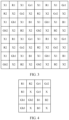
- the pixel array may include color pixels and X pixels. Refer to FIG. 2 .
- Color pixels may include red pixels (R1 and R2, where R represents red), green pixels (Gr1, Gr2, Gb 1, and Gb2, where both Gr and Gb represent green), and blue pixels (B 1 and B2, where B represents blue).
- X pixels are X1 and X2.
- the pixel array shown in FIG. 2 may be considered as a pixel array in an RGBX pattern (pattern). In the pixel array shown in FIG.
- X1 pixels form a first channel through which an infrared light beam (or a full-band light beam) passes
- four X2 pixels form another first channel through which an infrared light beam (or a full-band light beam) passes.
- R1, Gr1, Gb 1, and B1 form a second channel through which a visible light beam passes
- R2, Gr2, Gb2, and B2 form another second channel through which a visible light beam passes.
- the pixel array shown in FIG. 2 includes four channels in total, and the four channels include two first channels and two second channels. It should be noted that a minimum unit in an image is also referred to as a pixel.
- a pixel array includes but is not limited to the following several attributes, and the following several attributes of the pixel array are not limited in this embodiment.
- a first attribute is a quantity of a plurality of channels formed by pixels in a pixel array. In addition to the case in which there are four channels in FIG. 2 , there may alternatively be three, five, or more channels.
- a second attribute is a quantity of pixels in a pixel array.
- the quantity of pixels in the pixel array is not limited in this embodiment.
- the array including 16 pixels (4 ⁇ 4 pattern, pattern) shown in FIG. 2 is actually a minimum subarray in the pixel array, and the pixel array may be an array formed by a combination of one or more minimum subarrays.
- a case shown in FIG. 3 is a pixel array formed by a combination of four minimum subarrays.
- a third attribute is a quantity of first channels and a quantity of second channels in a plurality of channels formed by pixels.
- the four channels may alternatively include one first channel and three second channels, or three first channels and one channel.
- the four channels may alternatively include one first channel and three second channels, or three first channels and one channel.
- R1, Gr1, Gb1, and B1 form a 1 st second channel through which a visible light beam passes
- R2, Gr2, Gb2, and B2 form a 2 nd second channel through which a visible light beam passes
- R3, Gr3, Gb3, and B3 form a 3 rd second channel through which a visible light beam passes
- four X pixels form a first channel through which an infrared light beam passes.
- a fourth attribute is an arrangement order of pixels in a pixel array.
- R, Gr, Gb, and B pixels may be arranged in any order, and the R, Gr, Gb, and B pixels and X pixels may also be arranged in any order.
- the pixels included in the pixel array shown in FIG. 2 are the same as pixels included in a pixel array shown in FIG. 5 , but arrangement orders of the pixels in the two pixel arrays are different.
- a fifth attribute is a color pattern of color pixels in a pixel array.
- pixels forming the second channel may use different color patterns.
- the pixel arrays shown in FIG. 2 to FIG. 5 all use a red green blue (red green blue, RGB) color pattern.
- a pixel array shown in FIG. 6 may alternatively be obtained by using a red yellow blue (red yellow blue, RYB) color pattern, or a pixel array shown in FIG. 7 may be obtained by using a cyan magenta yellow (cyan magenta yellow, CMY) color pattern.
- each pixel in the pixel array corresponds to a horizontal switch and a vertical switch, horizontal switches corresponding to each row of pixels are controlled by using a horizontal register, and vertical switches corresponding to each column of pixels are controlled by using a vertical register.
- each pixel in the pixel array starts exposure, and the pixel is used to perform photoelectric conversion based on photons in the second light beam, to obtain an analog signal.
- the image sensor 102 further includes a time sequence control circuit, an analog signal processing element, and an analog-to-digital conversion element.
- the time sequence control circuit controls the horizontal register of each row and the vertical register of each column, so that the horizontal register of each row controls each horizontal switch of the row to be turned on, and the vertical register of each column controls each vertical switch of the column to be turned on.
- exposure of the pixel stops. Then, an analog signal obtained by performing photoelectric conversion based on the pixel between the start of exposure and the stop of exposure is read.
- the time sequence control circuit sends the read analog signal to the analog signal processing element, and the analog signal processing element may be configured to perform analog gain on the analog signal, to obtain an analog signal obtained after the analog gain.
- the analog signal obtained after the analog gain is sent to the analog-to-digital conversion element, and the analog-to-digital conversion element is configured to convert the analog signal obtained after the analog gain into a digital signal.
- the analog-to-digital conversion element may also perform digital gain on the digital signal obtained through conversion, to use a digital signal obtained after the digital gain as an electrical signal.
- the image sensor 102 performs, based on the brightness adjustment parameter corresponding to the first channel, photoelectric conversion on the infrared light beam that is in the second light beam and that is irradiated to the first channel, to obtain an electrical signal, and the obtained electrical signal is the first electrical signal.
- the image sensor 102 performs, based on the brightness adjustment parameter corresponding to the second channel, photoelectric conversion on the visible light beam that is in the second light beam and that is irradiated to the second channel, to obtain an electrical signal, and the obtained electrical signal is the second electrical signal.
- the image sensor 102 After obtaining the first electrical signal and the second electrical signal, the image sensor 102 further generates an initial image of the target object based on the first electrical signal and the second electrical signal. It should be noted that a quantity of pixels included in the initial image is consistent with a quantity of pixels included in the image sensor 102, and information about each pixel in the initial image is obtained by performing photoelectric conversion on a light beam by using one pixel in the image sensor 102. In other words, the pixels in the image sensor 102 are in a one-to-one correspondence with the pixels in the initial image. Because the color pixels and the X pixels in the image sensor 102 are usually arranged in an interleaved manner, color pixels and X pixels in the initial image are also arranged in an interleaved manner.
- the image sensor 102 further needs to send a color image and a grayscale image to the image processor 103 based on the initial image, to help the image processor 103 subsequently perform fusion processing.
- the color image is an image formed by the color pixels other than the X pixels in the initial image, and the color image is used to provide color information in the subsequent fusion processing.
- the grayscale image is an image formed by the X pixels in the initial image, and the grayscale image is used to provide brightness information in the subsequent fusion processing.
- an image that can provide brightness information in this embodiment is not limited to the grayscale image.
- the color image can also provide specific brightness information in the subsequent fusion processing.
- a process of obtaining the color image and the grayscale image based on the initial image may be locally performed by the image sensor 102, or the image sensor 102 may send the generated initial image to a digital signal processor (digital signal process, DSP), and the DSP performs the process of obtaining the color image and the grayscale image.
- DSP digital signal process
- the X pixels in the initial image may be removed while locations of the color pixels in the initial image remain unchanged
- the grayscale image is obtained based on the initial image
- the color pixels in the initial image may be removed while locations of the X pixels in the initial image remain unchanged.
- resolutions of both the color image and the grayscale image are the same as a resolution of the initial image.
- the resolution of the initial image is 10 ⁇ 10, that is, the initial image is an image including 10 pixels in each row and 10 pixels in each column, that is, 100 pixels in total
- the resolutions of the color image and the grayscale image are also 10 ⁇ 10.
- the color image includes only color pixels. Because the X pixels are removed, an original location of the X pixel is a blank location that does not include any pixel.
- the grayscale image includes only X pixels, and an original location of the color pixel is a blank location that does not include any pixel.
- the image sensor 102 is electrically connected to the image processor 103. Therefore, after obtaining the initial image, the image sensor 102 may send the obtained color image and grayscale image to the image processor 103 based on the initial image. If the color image and the grayscale image are obtained by splitting the initial image by the image sensor 102, the image sensor 102 directly sends the color image and the grayscale image to the image processor 103. After the image sensor 102 generates the initial image, if the image sensor 102 sends the initial image to the DSP, and the DSP splits the initial image to obtain a color image and a grayscale image, the DSP sends the color image and the grayscale image to the image processor 103.
- the image processor 103 is configured to: receive the color image and the grayscale image, and perform fusion processing on the color image and the grayscale image to obtain a fused image. Because the grayscale image can provide brightness information, the image processor 103 can better obtain color information provided by the color image, so that the obtained color information is relatively rich. Therefore, when the image processor element performs fusion processing based on the grayscale image and the color image, the obtained fused image has a relatively high signal-to-noise ratio and relatively good image quality.
- the image processor 103 may be a set of a plurality of processors including an image signal processor (image signal processing, ISP) and a fusion processor, or may be a single processor having both an ISP function and an image fusion function, to implement fusion processing on the color image and the grayscale image.
- ISP image signal processing
- the ISP is configured to perform interpolation processing on the color image and the grayscale image, to obtain a color image and a grayscale image that are obtained after the interpolation processing.
- the fusion processor is configured to perform fusion processing on the color image and the grayscale image that are obtained after the interpolation processing.
- two cases of the interpolation processing and fusion processing processes are separately described by using an example in which a color pattern used for a color image is an RGB pattern, that is, the color image includes red pixels, green pixels, and blue pixels.
- Case 1 When performing interpolation processing, the ISP first adjusts a color of any pixel in the color image and a grayscale image, to obtain a color image and a grayscale image that are obtained after the interpolation processing. Then, blank locations in the color image and the grayscale image that are obtained after the interpolation processing are supplemented, to obtain a supplemented color image and grayscale image. Then, the fusion processor performs fusion on the supplemented color image and grayscale image, to obtain a fused image.
- the ISP may adjust a color of the any pixel based on colors of other pixels around the any pixel.
- a red pixel in the color image is used as an example, and there are blue pixel and green pixel around the red pixel.
- the red pixel includes only red information.
- the ISP performs calculation based on the blue pixel and green pixel around the red pixel to obtain at least one piece of blue information and green information corresponding to the red pixel. Then, at least one piece of the blue information and the green information obtained through the calculation is superimposed on the red pixel. Therefore, the red pixel not only includes the red information, but also fuses the blue information and the green information, so that color information corresponding to the red pixel is richer.
- a grayscale value of the any X pixel is also adjusted based on grayscale values of other X pixels around the any X pixel, so that grayscale values corresponding to adjacent X pixels are close to each other, to ensure that brightness information provided by the adjacent X pixels is relatively consistent, and further ensure that a subsequently generated fused image has uniform brightness.
- the color image and the grayscale image that are obtained after the interpolation processing may be obtained by performing the foregoing color adjustment process.
- the color image and the grayscale image that are obtained after the interpolation processing include pixels obtained after the color adjustment and blank locations. Therefore, the ISP further supplements each blank location. For example, for any blank location in a color image or a grayscale image, the ISP determines, based on a color of each pixel around the blank location, a color corresponding to the blank location, to supplement the blank location. It can be learned that a supplemented color image and grayscale image no longer include the blank location. In the color image, because any color pixel around the blank location includes at least two colors, at least two colors correspond to the blank location, so that the blank location has relatively rich color information.
- colors of pixels in the color image and the grayscale image are first adjusted, and then blank locations are supplemented based on pixels whose colors are adjusted.
- the blank location may also be directly supplemented in a manner of adjusting a color of a pixel.
- the ISP directly determines a color of the any blank location based on a pixel, whose color is not adjusted, around the any blank location, to supplement the blank location.
- the fusion processor may perform fusion processing on corresponding pixels, to obtain a fused image. It may be understood that, for any pixel in the fused image, the pixel can provide both color information and brightness information.
- Case 2 The ISP adjusts a color of any pixel in the color image and a grayscale image, to obtain a color image and a grayscale image that are obtained after the interpolation processing. Then, the fusion processor first supplements blank locations in the color image and the grayscale image that are obtained after the interpolation processing, to obtain a supplemented color image and grayscale image, and then the fusion processor fuses the supplemented color image and the grayscale image, to obtain a fused image.
- the ISP adjusts a color of the any pixel based on a color of another pixel around the any pixel.
- a color adjustment process is the same as the color adjustment process in Case 1. It should be noted that the foregoing interpolation processing is performed only for a pixel that is in a color image and a grayscale image and that is not located in a blank location. For blank locations in the color image and the grayscale image, the ISP element does not perform any adjustment on a color of any blank location based on another pixel around the blank location. In other words, after the interpolation processing is performed, blank locations in the color image and the grayscale image that are obtained after the interpolation processing remain in a blank state.
- the ISP After performing the interpolation processing, the ISP sends the color image and the grayscale image that are obtained after the interpolation processing to the fusion processor, so that the fusion processor performs fusion processing.
- the fusion processor first supplements the blank locations in the color image and the grayscale image that are obtained after the interpolation processing, to obtain a supplemented color image and a grayscale image, and then performs fusion on the supplemented color image and the grayscale image.
- supplement and fusion processes refer to the descriptions in Case 1. Details are not described herein again.
- a camera provided in embodiments of this application can separately image an infrared light beam and a visible light beam by using the single image sensor, and does not need to use a light-splitting prism.
- the camera has a simple structure and is easy to process, which helps improve a yield rate and reduce production costs.
- the first channel and the second channel included in the image sensor are independently controlled, and have respective corresponding brightness adjustment parameters. Therefore, the first channel may perform, based on the brightness adjustment parameter corresponding to the first channel, photoelectric conversion on the infrared light beam irradiated on the first channel, to obtain the first electrical signal.
- the second channel may also perform, based on the brightness adjustment parameter corresponding to the second channel, photoelectric conversion on the visible light beam irradiated to the second channel, to obtain the second electrical signal.
- the initial image of the target object may be generated based on the first electrical signal and the second electrical signal, to send the color image and the grayscale image to the image processor based on the initial image. This ensures that the color image generated based on the visible light beam and the grayscale image generated based on the infrared light beam are pixel-level aligned.
- the apparatus may further include an encoding element 104, and the encoding element 104 is electrically connected to the image processor 103.
- the encoding element 104 may encode the fused image of the target object, or may continue to wait for a subsequent one or more frames of fused images and the fused image of the target object to form a video stream, and then encode the video stream.
- a function of encoding is to compress an image or a video stream, to reduce a quantity of bytes occupied by the image or the video stream, and facilitate storage and transmission of the image or the video stream.
- the optical module 101 includes a band-pass optical filter.
- the band-pass optical filter is configured to filter the first light beam to obtain the infrared light beam and the visible light beam as the second light beam.
- the bandpass optical filter is an optical filter that allows only a light beam of a first reference band to pass through.
- the band-pass optical filter is a two-pass optical filter by setting the first reference band as an infrared light beam band and a visible light beam band.
- the band-pass optical filter can filter the first light beam to obtain the infrared light beam and the visible light beam, so that the infrared light beam and the visible light beam serve as the second light beam.
- the infrared light beam obtained by filtering the first light beam by the band-pass optical filter may be an infrared light beam of a full infrared band, or may be an infrared light beam of a fixed band, for example, an infrared light beam in a band about 850 nm.
- a horizontal coordinate is a wavelength of a light beam
- a vertical coordinate is a transmittance rate of a light beam.
- the infrared light beam includes a first infrared light beam in a band near 850 nm and a second infrared light beam in a band near 850 nm. That is, the band-pass optical filter allows the visible light beam and the infrared light beams of two different bands to pass through, and the band-pass optical filter is a tri-pass optical filter. It should be noted that, for a target object made of some materials, reflectivity of a material of the target object for the first infrared light beam and the visible light beam is different. As a result, an imaging effect of the target object in the first infrared light beam is different from an imaging effect of the target object in the visible light beam.
- the band of the second infrared light beam is located between the band of the first infrared light beam and the band of the visible light beam, compared with that of the first infrared light beam, the band of the second infrared light beam is closer to the band of the visible light beam. Therefore, imaging the target object under the second infrared light beam can eliminate an imaging difference between the first infrared light beam and the visible light beam, thereby improving image quality of a subsequently obtained image.
- the first infrared light beam and the second infrared light beam shown in FIG. 10 are merely examples.
- the band of the first infrared light beam is near 850 nm and the band of the second infrared light beam is near 750 nm
- the band of the first infrared light beam and the band of the second infrared light beam may alternatively be any near-infrared band.
- the band of the first infrared light beam and the band of the second infrared light beam are not limited in embodiments of this application.
- the image sensor 102 is further configured to perform, based on the brightness adjustment parameter corresponding to the first channel, photoelectric conversion on the visible light beam that is in the second light beam and that is irradiated to the first channel, to obtain a second electrical signal.
- the first channel may not only be configured to allow the infrared light beam to pass through, but also be configured to allow the infrared light beam and the visible light beam to pass through.
- a band-stop optical filter membrane is disposed on a surface of the image sensor 102, and the band-stop optical filter membrane is configured to shielding the infrared light beam in the second light beam, so that the visible light beam in the second light beam is irradiated to the second channel, and the infrared light beam in the second light beam is prevented from being irradiated to the second channel.
- the band-stop optical filter membrane is an optical filter membrane configured to prevent a light beam of a second reference band from passing through. By setting the second reference band as a band of the infrared light beam, the band-stop optical filter membrane may shield the infrared light beam in the second light beam.
- the band-stop optical filter membrane may also be referred to as an infrared light beam suppression (suppress infrared radiation, SIR) optical filter membrane.
- FIG. 11 shows a response curve of a band-stop optical filter membrane. It can be seen that the band-stop optical filter membrane can shield an infrared light beam in a band between 600 nm and 900 nm.
- the band-stop optical filter membrane can shield an infrared light beam in a band between 600 nm and 900 nm.
- the infrared light beam in the second light beam may be prevented from being irradiated to the second channel. This avoids impact of the infrared light beam in the second channel on the visible light beam, for example, a color cast problem of the visible light beam caused by the infrared light beam.
- the brightness adjustment parameter includes at least one of exposure duration and a gain.
- the exposure duration affects a quantity of photons received by each pixel in a channel.
- longer exposure duration indicates a larger quantity of photons received by each pixel in the channel, and a higher signal-to-noise ratio and higher definition of a subsequently obtained fused image.
- a value of the brightness adjustment parameter corresponding to the first channel is different from a value of the brightness adjustment parameter corresponding to the second channel may mean that a type of the brightness adjustment parameter corresponding to the first channel is different from a type of the brightness adjustment parameter corresponding to the second channel.
- the brightness adjustment parameter corresponding to the first channel is exposure duration
- the brightness adjustment parameter corresponding to the second channel is a gain
- the brightness adjustment parameter corresponding to the first channel is a gain
- the brightness adjustment parameter corresponding to the second channel is exposure duration.
- the brightness adjustment parameter corresponding to the first channel is exposure duration or a gain
- the brightness adjustment parameter corresponding to the second channel is exposure duration and a gain.
- the brightness adjustment parameter corresponding to the first channel is exposure duration and a gain
- the brightness adjustment parameter corresponding to the second channel is exposure duration or a gain.
- a value of the brightness adjustment parameter corresponding to the first channel is different from a value of the brightness adjustment parameter corresponding to the second channel may alternatively mean that a type of the brightness adjustment parameter corresponding to the first channel is the same as a type of the brightness adjustment parameter corresponding to the second channel, but the values are different.
- both the brightness adjustment parameter corresponding to the first channel and the brightness adjustment parameter corresponding to the second channel are exposure duration.
- the exposure duration corresponding to the first channel may be 10 milliseconds
- the exposure duration corresponding to the second channel may be duration other than 10 milliseconds, for example, 15 milliseconds.
- the camera receives less visible light, but sufficient infrared light.
- exposure duration of a selected color channel (the second channel) is longer than exposure duration of a black-and-white channel (the first channel)
- the color channel can be fully exposed without causing overexposure of the black-and-white channel. Therefore, an imaging effect of the camera in a low-illuminance environment is improved.
- a gain of the color channel may also be set to be greater than a gain of the black-and-white channel.
- the gain may include at least one of an analog gain and a digital gain.
- the analog gain indicates amplification of an analog signal
- the digital gain indicates amplification of a digital signal. It should be noted that, in a process of gaining a signal, noise included in the signal is also amplified, to affect quality of an image. Therefore, the gain is often used when the signal is weak and the exposure duration cannot continue to increase.
- the image processor 103 is further configured to adjust, based on brightness information of the grayscale image, the brightness adjustment parameter corresponding to the first channel, and adjust, based on brightness information of the color image, the brightness adjustment parameter corresponding to the second channel.
- the brightness adjustment parameter corresponding to the second channel is to be adjusted. Because the second channel is a channel allowing a visible light beam to pass through, an image generated based on the second electrical signal obtained through conversion in the second channel is a color image. In response to a fact that the brightness information of the color image meets a requirement, it indicates that the brightness adjustment parameter corresponding to the second channel is applicable to the current ambient brightness. Therefore, the second channel may continue to use the currently corresponding brightness adjustment parameter to perform photoelectric conversion.
- the image processor 103 may send a signal to the time sequence control circuit in the image sensor 102, so that the time sequence control circuit adjusts time for turning on the horizontal switch and the vertical switch by the horizontal register and the vertical register, to change exposure duration of each pixel in the channel that needs to be adjusted.
- the signal sent by the image processor 103 to the time sequence control circuit in the image sensor 102 may be a register value corresponding to the horizontal register and a register value corresponding to the vertical register.
- the horizontal register and the vertical register respectively adjust, based on the respective register values corresponding to the horizontal register and the vertical register, the time for turning on the horizontal switch and the vertical switch.
- the image processor 103 may send a signal to the analog signal processing element in the image sensor 102, so that the analog signal processing element adjusts an analog gain multiple for the analog signal.
- the image processor 103 may send a signal to the analog-to-digital conversion element in the image sensor 102, so that the analog-to-digital conversion element adjusts a digital gain multiple for the digital signal.
- an embodiment provides an image obtaining method. Refer to FIG. 12 , and the method includes the following steps.
- Step 1201 Collect a first light beam by using an optical module, and obtain a second light beam based on the first light beam, where the second light beam includes a visible light beam and an infrared light beam.
- a target object whose image is to be shot may reflect a light beam or directly emit a light beam.
- the reflected light beam or the directly emitted light beam may be used as the first light beam by using the optical module 101.
- the second light beam including the visible light beam and the infrared light beam is obtained based on the first light beam.
- the first light beam may be directly used as the second light beam.
- the second light beam needs to be obtained by filtering the first light beam.
- the step of obtaining a second light beam based on the first light beam includes: filtering the first light beam to obtain an infrared light beam and a visible light beam as the second light beam.
- the foregoing filtering process may be implemented by using the band-pass optical filter in the optical module 101.
- the infrared light beam includes a first infrared light beam in a band near 850 nm and a second infrared light beam in a band near 750 nm.
- the bands of the visible light beam, the second infrared light beam, and the first infrared light beam increase successively.
- Light compensation is performed on the visible light beam by using two infrared light beams of different bands, so that a light compensation effect is relatively good and definition of a subsequently obtained image is ensured.
- Step 1202 Perform, by an image sensor based on a brightness adjustment parameter corresponding to a first channel of the image sensor, photoelectric conversion on the infrared light beam that is in the second light beam and that is irradiated to the first channel, to obtain a first electrical signal; and perform, based on a brightness adjustment parameter corresponding to a second channel of the image sensor, photoelectric conversion on the visible light beam that is in the second light beam and that is irradiated to the second channel, to obtain a second electrical signal, where a value of the brightness adjustment parameter corresponding to the first channel is different from a value of the brightness adjustment parameter corresponding to the second channel.
- Both the first channel and the second channel are channels that are included in the image sensor and that can be independently controlled, each channel corresponds to a brightness adjustment parameter, and brightness adjustment parameters corresponding to different channels may be different.
- each channel includes a plurality of pixels, and pixels of different channels are different.
- a value of the brightness adjustment parameter corresponding to the first channel and a value of the brightness adjustment parameter corresponding to the second channel may also be a same value, and are not limited to different values.
- the brightness adjustment parameter corresponding to the first channel and the brightness adjustment parameter corresponding to the second channel each include at least one of exposure duration and a gain.
- the exposure duration affects a quantity of photons received by each pixel in a channel.
- longer exposure duration indicates a larger quantity of photons received by each pixel, a higher signal-to-noise ratio of a subsequently obtained image, and a clearer image.
- Gains include an analog gain and a digital gain. The essence of the two types of gains is to amplify signals.
- the brightness adjustment parameter is exposure duration.
- exposure duration used by the first channel that is configured to allow the infrared light beam to pass through is relatively short. Otherwise, an overexposure phenomenon occurs on the first channel.
- the second channel configured to allow the visible light beam to pass through because illuminance is relatively low and a quantity of photons included in the light is relatively small, relatively long exposure duration is applicable.
- the second channel configured to allow the visible light beam to pass through needs to accommodate the first channel configured to allow the infrared light beam to pass through, and both the first channel and the second channel need to use relatively short exposure duration to avoid overexposure of the first channel configured to allow the infrared light beam to pass through.
- the relatively short exposure duration causes a relatively small quantity of photons obtained through the second channel configured to allow the visible light beam to pass through, and relatively poor quality of a subsequently obtained image.
- both the first channel and the second channel may use brightness adjustment parameter information applicable to the channels.
- the low light scene in the foregoing example is still used as an example.
- the brightness adjustment parameter corresponding to the first channel configured to allow the infrared light beam to pass through may be relatively short exposure duration, to avoid overexposure
- the brightness adjustment parameter corresponding to the second channel configured to allow the visible light beam to pass through may be relatively long exposure duration, to ensure that a sufficient quantity of photons can be obtained.
- a high-quality color image with uniform brightness and a relatively high signal-to-noise ratio can be obtained in the low light scene.
- different first channels configured to allow infrared light beams to pass through may also use different brightness adjustment parameters
- different second channels configured to allow visible light beams to pass through may also use different brightness adjustment parameters.
- a quantity of the first channels configured to allow the infrared light beams to pass through is more than two
- the more than two first channels may respectively use different brightness adjustment parameters.
- one first channel configured to allow the infrared light beam to pass through uses relatively short exposure duration
- the other first channel configured to allow the infrared light beam to pass through uses relatively long exposure duration.
- the two first channels may alternatively respectively use different gains. In this way, both a target object at a relatively bright close place and a target object at a relatively dark remote place can obtain sufficient brightness, and brightness of the two target objects can be consistent with each other, so that an image with a relatively high signal-to-noise ratio and uniform brightness is obtained.
- a same brightness adjustment parameter may also be used for each channel.
- a brightness adjustment parameter corresponding to each channel may be relatively long exposure duration.
- the brightness adjustment parameter corresponding to each channel may be relatively short exposure duration.
- the method further includes: performing, by using the image sensor based on the brightness adjustment parameter corresponding to the first channel, photoelectric conversion on the visible light beam that is in the second light beam and that is irradiated to the first channel, to obtain a second electrical signal.
- the first channel may be configured to perform photoelectric conversion only on the infrared light beam, or may be configured to perform photoelectric conversion on both the infrared light beam and the visible light beam.
- a band-stop optical filter membrane is disposed on a surface of the image sensor.
- the performing, based on a brightness adjustment parameter corresponding to a second channel of the image sensor, photoelectric conversion on the visible light beam that is in the second light beam and that is irradiated to the second channel, to obtain a second electrical signal includes: shielding the infrared light beam in the second light beam by the band-stop optical filter membrane, so that the visible light beam in the second light beam is irradiated to the second channel, and the infrared light beam in the second light beam is prevented from being irradiated to the second channel.
- the band-stop optical filter membrane When the second light beam is propagated to the band-stop optical filter membrane, only the visible light beam in the second light beam can pass through the band-stop optical filter membrane and be irradiated to the second channel, and the infrared light beam in the second light beam is shielded by the band-stop optical filter membrane and cannot be irradiated to the second channel. In this way, the performing, based on the brightness adjustment parameter corresponding to the second channel, photoelectric conversion on only the visible light beam that is in the second light beam and that is irradiated to the second channel, to obtain the second electrical signal is implemented.
- Step 1203 Generate an initial image of the target object based on the first electrical signal and the second electrical signal, and send a color image and a grayscale image to an image processor based on the initial image.
- the image sensor generates the initial image of the target object based on the first electrical signal and the second electrical signal. Because the first electrical signal is a signal obtained by performing photoelectric conversion on the infrared light beam, and the second electrical signal is a signal obtained by performing photoelectric conversion on the visible light beam, the initial image generated based on the first electrical signal and the second electrical signal includes both brightness information provided by the infrared light beam and color information provided by the visible light beam. Certainly, information that can be provided by the visible light beam is not limited to color information. For example, the visible light beam can also provide specific brightness information.
- a color image used to reflect color information and a grayscale image used to reflect brightness information may be further obtained based on the initial image.
- a process of obtaining the color image and the grayscale image may be locally executed by the image sensor, or may be executed by a DSP other than the image sensor.
- An execution body is not limited in this embodiment. Regardless of which execution body is used to obtain the color image and the grayscale image, the obtained color image and the grayscale image may be further sent to the image processor, so that the image processor performs fusion processing.
- Step 1204 Receive the color image and the grayscale image by the image processor, and perform fusion processing on the color image and the grayscale image to obtain a fused image.
- the image processor first performs interpolation processing on the color image and the grayscale image to obtain a color image and a grayscale image that are obtained through the interpolation processing, and then performs fusion on the color image and the grayscale image that are obtained through the interpolation processing, to obtain a fused image of the target object.
- the fused image is an image with a relatively high signal-to-noise ratio and uniform brightness.
- the method further includes: adjusting, based on brightness information of the grayscale image, the brightness adjustment parameter corresponding to the first channel, and adjusting, based on brightness information of the color image, the brightness adjustment parameter corresponding to the second channel.
- the image processor may analyze the brightness information of the grayscale image and the brightness information of the color image, to adjust the brightness adjustment parameters of the first channel and the second channel based on analysis results. For example, when brightness indicated by the brightness information of the color image is relatively low, the image processor may increase exposure duration corresponding to the second channel, to obtain a larger quantity of photons by using the second channel, and improve brightness and a signal-to-noise ratio of the image. For another example, when overexposure occurs on the grayscale image, the image processor may shorten the exposure duration corresponding to the first channel, to obtain a grayscale image with normal exposure.
- a process in which the image processor adjusts the brightness adjustment parameter corresponding to each channel may be iteratively performed for multiple times in a process of obtaining the fused image.
- An occasion for adjusting the brightness adjustment parameter is not limited in this embodiment.
- the image processor may perform analysis based on the last obtained frame of image in the reference quantity of frames of images, to adjust a brightness adjustment parameter corresponding to each channel once.
- the last obtained frame of image may be analyzed at intervals of reference duration, to adjust a brightness adjustment parameter corresponding to each channel once.
- the camera provided in embodiments of this application can separately image an infrared light beam and a visible light beam by using a single image sensor, and does not need to use a light-splitting prism.
- the first channel and the second channel included in the image sensor may be independently controlled, and have respective corresponding brightness adjustment parameters. Therefore, in the first channel, photoelectric conversion may be performed, based on the brightness adjustment parameter corresponding to the first channel, on the infrared light beam irradiated on the first channel, to obtain the first electrical signal.
- photoelectric conversion may be performed, based on the brightness adjustment parameter corresponding to the second channel, on the visible light beam irradiated to the second channel, to obtain the second electrical signal; and in the second channels configured to allow the visible light beams to pass through, photoelectric conversion may be performed, based on the respective corresponding brightness adjustment parameters, on the visible light beam irradiated to the second channel, to obtain the second electrical signals.
- the initial image of the target object may be generated based on the first electrical signal and the second electrical signal, to send the color image and the grayscale image to the image processor based on the initial image.
- All or some of the foregoing embodiments may be implemented by using software, hardware, firmware, or any combination thereof.
- the software is used to implement the embodiments, all or some of the embodiments may be implemented in a form of a computer program product.
- the computer program product includes one or more computer instructions.
- the computer may be a general-purpose computer, a dedicated computer, a computer network, or another programmable apparatus.
- the computer instructions may be stored in a computer-readable storage medium or may be transmitted from a computer-readable storage medium to another computer-readable storage medium.
- the computer instructions may be transmitted from a website, computer, server, or data center to another website, computer, server, or data center in a wired (for example, a coaxial cable, an optical fiber, or a digital subscriber line) or wireless (for example, infrared, radio, or microwave) manner.
- the computer-readable storage medium may be any usable medium accessible by the computer, or a data storage device, such as a server or a data center, integrating one or more usable media.
- the usable medium may be a magnetic medium (for example, a floppy disk, a hard disk, or a magnetic tape), an optical medium (for example, a DVD), or a semiconductor medium (for example, a solid-state drive Solid State Disk).
Landscapes
- Engineering & Computer Science (AREA)
- Multimedia (AREA)
- Signal Processing (AREA)
- Studio Devices (AREA)
- Color Television Image Signal Generators (AREA)
Applications Claiming Priority (1)
| Application Number | Priority Date | Filing Date | Title |
|---|---|---|---|
| PCT/CN2020/087878 WO2021217521A1 (zh) | 2020-04-29 | 2020-04-29 | 摄像机及获取图像的方法 |
Publications (2)
| Publication Number | Publication Date |
|---|---|
| EP4131916A1 true EP4131916A1 (de) | 2023-02-08 |
| EP4131916A4 EP4131916A4 (de) | 2023-05-17 |
Family
ID=78331588
Family Applications (1)
| Application Number | Title | Priority Date | Filing Date |
|---|---|---|---|
| EP20933350.9A Pending EP4131916A4 (de) | 2020-04-29 | 2020-04-29 | Kamera und bilderfassungsverfahren |
Country Status (4)
| Country | Link |
|---|---|
| US (1) | US12108197B2 (de) |
| EP (1) | EP4131916A4 (de) |
| CN (1) | CN113940052B (de) |
| WO (1) | WO2021217521A1 (de) |
Families Citing this family (4)
| Publication number | Priority date | Publication date | Assignee | Title |
|---|---|---|---|---|
| KR20240081893A (ko) * | 2022-12-01 | 2024-06-10 | 삼성전자주식회사 | 이미지 센싱 장치 및 이미지 신호 처리 방법 |
| CN116758447B (zh) * | 2023-04-26 | 2026-02-10 | 中国能源建设集团广东省电力设计研究院有限公司 | 一种基于视频融合技术的变电站设备故障分析系统 |
| TWI873867B (zh) * | 2023-09-22 | 2025-02-21 | 虹光精密工業股份有限公司 | 產生含有透明度及可見光資訊的影像檔的掃描裝置 |
| CN117201693B (zh) * | 2023-11-01 | 2024-01-16 | 长春汽车工业高等专科学校 | 一种物联网图像压缩方法、装置、终端设备及介质 |
Family Cites Families (13)
| Publication number | Priority date | Publication date | Assignee | Title |
|---|---|---|---|---|
| US8755597B1 (en) * | 2011-02-24 | 2014-06-17 | Exelis, Inc. | Smart fusion of visible and infrared image data |
| KR101695252B1 (ko) * | 2012-06-07 | 2017-01-13 | 한화테크윈 주식회사 | 멀티 대역 필터 어레이 기반 카메라 시스템 및 그의 영상 처리 방법 |
| WO2013183886A1 (en) * | 2012-06-07 | 2013-12-12 | Samsung Techwin Co., Ltd | Camera system with multi-spectral filter array and image processing method thereof |
| KR101858646B1 (ko) * | 2012-12-14 | 2018-05-17 | 한화에어로스페이스 주식회사 | 영상 융합 장치 및 방법 |
| JP6264233B2 (ja) * | 2014-09-02 | 2018-01-24 | 株式会社Jvcケンウッド | 撮像装置、撮像装置の制御方法及び制御プログラム |
| CN107438170B (zh) * | 2016-05-25 | 2020-01-17 | 杭州海康威视数字技术股份有限公司 | 一种图像透雾方法及实现图像透雾的图像采集设备 |
| CN108419062B (zh) * | 2017-02-10 | 2020-10-02 | 杭州海康威视数字技术股份有限公司 | 图像融合设备和图像融合方法 |
| CN108419061B (zh) * | 2017-02-10 | 2020-10-02 | 杭州海康威视数字技术股份有限公司 | 基于多光谱的图像融合设备、方法及图像传感器 |
| CN109688317A (zh) * | 2017-10-18 | 2019-04-26 | 杭州海康威视数字技术股份有限公司 | 一种摄像机以及图像生成方法 |
| CN109951646B (zh) * | 2017-12-20 | 2021-01-15 | 杭州海康威视数字技术股份有限公司 | 图像融合方法、装置、电子设备及计算机可读存储介质 |
| CN108965654B (zh) * | 2018-02-11 | 2020-12-25 | 浙江宇视科技有限公司 | 基于单传感器的双光谱摄像机系统和图像处理方法 |
| JP7171254B2 (ja) * | 2018-06-13 | 2022-11-15 | キヤノン株式会社 | 画像処理装置、撮像装置、および画像処理方法 |
| CN110798623A (zh) * | 2019-10-15 | 2020-02-14 | 华为技术有限公司 | 单目摄像机、图像处理系统以及图像处理方法 |
-
2020
- 2020-04-29 EP EP20933350.9A patent/EP4131916A4/de active Pending
- 2020-04-29 CN CN202080001758.0A patent/CN113940052B/zh active Active
- 2020-04-29 WO PCT/CN2020/087878 patent/WO2021217521A1/zh not_active Ceased
-
2022
- 2022-10-26 US US17/974,302 patent/US12108197B2/en active Active
Also Published As
| Publication number | Publication date |
|---|---|
| EP4131916A4 (de) | 2023-05-17 |
| US20230049248A1 (en) | 2023-02-16 |
| CN113940052A (zh) | 2022-01-14 |
| CN113940052B (zh) | 2023-01-20 |
| US12108197B2 (en) | 2024-10-01 |
| WO2021217521A1 (zh) | 2021-11-04 |
Similar Documents
| Publication | Publication Date | Title |
|---|---|---|
| US12108197B2 (en) | Cameras and image obtaining methods based on controlling brightness adjustment parameters | |
| US10412314B2 (en) | Systems and methods for photometric normalization in array cameras | |
| EP3582494B1 (de) | Vorrichtung und verfahren zur fusion von mehrfachspekturmsbasierten bildern, und bildsensor | |
| US8125543B2 (en) | Solid-state imaging device and imaging apparatus with color correction based on light sensitivity detection | |
| CN103327342B (zh) | 具有透明滤波器像素的成像系统 | |
| US10931893B2 (en) | Image sensor, image processing apparatus and method, and program | |
| US7860307B2 (en) | Color matching method, and image capturing device and electronic apparatus using the same | |
| US20190378258A1 (en) | Image Fusion Apparatus and Image Fusion Method | |
| EP3902242B1 (de) | Bildsensor und signalverarbeitungsverfahren | |
| US20220182562A1 (en) | Imaging apparatus and method, and image processing apparatus and method | |
| US11647302B2 (en) | Method of calibrating image sensor and device for calibrating image sensor | |
| US11460666B2 (en) | Imaging apparatus and method, and image processing apparatus and method | |
| US20120274799A1 (en) | Calibrating image sensors | |
| US8023016B2 (en) | Imaging device and manufacturing method thereof | |
| US20180152683A1 (en) | Image processing method, imaging apparatus, and method performed thereby | |
| US8929682B2 (en) | Calibrating image sensors | |
| TW202348017A (zh) | 影像感測電路和影像感測裝置 | |
| WO2025218599A1 (zh) | 摄像头模组、电子设备、拍摄方法及装置 | |
| US9813687B1 (en) | Image-capturing device, image-processing device, image-processing method, and image-processing program | |
| JP2008113236A (ja) | 撮像装置におけるシェーディング補正方法と装置 | |
| JP7147841B2 (ja) | 撮像装置および方法、画像処理装置および方法、並びに、撮像素子 | |
| US10937230B2 (en) | Image processing | |
| JP4323043B2 (ja) | 固体撮像装置および光学フィルタ | |
| WO2015008383A1 (ja) | 撮像装置 | |
| US20190364200A1 (en) | Image capturing apparatus, image processing apparatus, and method |
Legal Events
| Date | Code | Title | Description |
|---|---|---|---|
| STAA | Information on the status of an ep patent application or granted ep patent |
Free format text: STATUS: THE INTERNATIONAL PUBLICATION HAS BEEN MADE |
|
| PUAI | Public reference made under article 153(3) epc to a published international application that has entered the european phase |
Free format text: ORIGINAL CODE: 0009012 |
|
| STAA | Information on the status of an ep patent application or granted ep patent |
Free format text: STATUS: REQUEST FOR EXAMINATION WAS MADE |
|
| 17P | Request for examination filed |
Effective date: 20221104 |
|
| AK | Designated contracting states |
Kind code of ref document: A1 Designated state(s): AL AT BE BG CH CY CZ DE DK EE ES FI FR GB GR HR HU IE IS IT LI LT LU LV MC MK MT NL NO PL PT RO RS SE SI SK SM TR |
|
| REG | Reference to a national code |
Ref country code: DE Ref legal event code: R079 Free format text: PREVIOUS MAIN CLASS: H04N0005225000 Ipc: H04N0023110000 |
|
| A4 | Supplementary search report drawn up and despatched |
Effective date: 20230417 |
|
| RIC1 | Information provided on ipc code assigned before grant |
Ipc: H04N 23/60 20230101ALI20230411BHEP Ipc: H04N 23/55 20230101ALI20230411BHEP Ipc: H04N 23/12 20230101ALI20230411BHEP Ipc: H04N 23/11 20230101AFI20230411BHEP |
|
| DAV | Request for validation of the european patent (deleted) | ||
| DAX | Request for extension of the european patent (deleted) | ||
| STAA | Information on the status of an ep patent application or granted ep patent |
Free format text: STATUS: EXAMINATION IS IN PROGRESS |
|
| 17Q | First examination report despatched |
Effective date: 20241218 |