EP4131933A1 - Procédé et dispositif de génération d'images - Google Patents
Procédé et dispositif de génération d'images Download PDFInfo
- Publication number
- EP4131933A1 EP4131933A1 EP21796787.6A EP21796787A EP4131933A1 EP 4131933 A1 EP4131933 A1 EP 4131933A1 EP 21796787 A EP21796787 A EP 21796787A EP 4131933 A1 EP4131933 A1 EP 4131933A1
- Authority
- EP
- European Patent Office
- Prior art keywords
- model
- image
- photographed object
- images
- ambient light
- Prior art date
- Legal status (The legal status is an assumption and is not a legal conclusion. Google has not performed a legal analysis and makes no representation as to the accuracy of the status listed.)
- Pending
Links
Images


Classifications
-
- G—PHYSICS
- G06—COMPUTING OR CALCULATING; COUNTING
- G06T—IMAGE DATA PROCESSING OR GENERATION, IN GENERAL
- G06T17/00—Three-dimensional [3D] modelling for computer graphics
-
- G—PHYSICS
- G06—COMPUTING OR CALCULATING; COUNTING
- G06T—IMAGE DATA PROCESSING OR GENERATION, IN GENERAL
- G06T11/00—Two-dimensional [2D] image generation
-
- G—PHYSICS
- G06—COMPUTING OR CALCULATING; COUNTING
- G06T—IMAGE DATA PROCESSING OR GENERATION, IN GENERAL
- G06T15/00—Three-dimensional [3D] image rendering
-
- G—PHYSICS
- G06—COMPUTING OR CALCULATING; COUNTING
- G06T—IMAGE DATA PROCESSING OR GENERATION, IN GENERAL
- G06T15/00—Three-dimensional [3D] image rendering
- G06T15/50—Lighting effects
- G06T15/506—Illumination models
-
- G—PHYSICS
- G06—COMPUTING OR CALCULATING; COUNTING
- G06T—IMAGE DATA PROCESSING OR GENERATION, IN GENERAL
- G06T19/00—Manipulating three-dimensional [3D] models or images for computer graphics
- G06T19/20—Editing of three-dimensional [3D] images, e.g. changing shapes or colours, aligning objects or positioning parts
-
- G—PHYSICS
- G06—COMPUTING OR CALCULATING; COUNTING
- G06T—IMAGE DATA PROCESSING OR GENERATION, IN GENERAL
- G06T7/00—Image analysis
- G06T7/50—Depth or shape recovery
-
- H—ELECTRICITY
- H04—ELECTRIC COMMUNICATION TECHNIQUE
- H04N—PICTORIAL COMMUNICATION, e.g. TELEVISION
- H04N5/00—Details of television systems
- H04N5/222—Studio circuitry; Studio devices; Studio equipment
- H04N5/262—Studio circuits, e.g. for mixing, switching-over, change of character of image, other special effects ; Cameras specially adapted for the electronic generation of special effects
- H04N5/265—Mixing
-
- G—PHYSICS
- G06—COMPUTING OR CALCULATING; COUNTING
- G06T—IMAGE DATA PROCESSING OR GENERATION, IN GENERAL
- G06T19/00—Manipulating three-dimensional [3D] models or images for computer graphics
- G06T19/003—Navigation within 3D models or images
-
- G—PHYSICS
- G06—COMPUTING OR CALCULATING; COUNTING
- G06T—IMAGE DATA PROCESSING OR GENERATION, IN GENERAL
- G06T2200/00—Indexing scheme for image data processing or generation, in general
- G06T2200/04—Indexing scheme for image data processing or generation, in general involving 3D image data
-
- G—PHYSICS
- G06—COMPUTING OR CALCULATING; COUNTING
- G06T—IMAGE DATA PROCESSING OR GENERATION, IN GENERAL
- G06T2207/00—Indexing scheme for image analysis or image enhancement
- G06T2207/20—Special algorithmic details
- G06T2207/20212—Image combination
- G06T2207/20221—Image fusion; Image merging
-
- G—PHYSICS
- G06—COMPUTING OR CALCULATING; COUNTING
- G06T—IMAGE DATA PROCESSING OR GENERATION, IN GENERAL
- G06T2207/00—Indexing scheme for image analysis or image enhancement
- G06T2207/30—Subject of image; Context of image processing
- G06T2207/30196—Human being; Person
- G06T2207/30201—Face
-
- G—PHYSICS
- G06—COMPUTING OR CALCULATING; COUNTING
- G06T—IMAGE DATA PROCESSING OR GENERATION, IN GENERAL
- G06T2219/00—Indexing scheme for manipulating 3D models or images for computer graphics
- G06T2219/20—Indexing scheme for editing of 3D models
- G06T2219/2012—Colour editing, changing, or manipulating; Use of colour codes
Definitions
- This application relates to the field of terminal device technologies, and in particular, to an image generation method and apparatus.
- a plurality of photographing apparatuses may be disposed on a terminal device.
- the plurality of photographing apparatuses may include a front-facing camera, and a user may take a selfie by using the front-facing camera.
- a front-facing camera may include a front-facing camera, and a user may take a selfie by using the front-facing camera.
- a three-dimensional sense and skin details of an image obtained by taking a selfie are usually missing, and there is more noise. Consequently, user experience is relatively poor.
- light filling is usually performed by using a display of a terminal device or a built-in illuminator.
- the terminal device may detect ambient light luminance of a photographing environment.
- the display of the terminal device or the built-in illuminator may be enabled to fill light, to improve a photographing effect of an image.
- a face can only receive light partially, and the luminance is limited.
- the three-dimensional sense and the skin details of the image obtained by taking a selfie are still missing, and the selfie effect is still poor.
- light filling may be further performed by using an external fill light device.
- the selfie effect is relatively good, but the fill light device needs to be set by the user, and is inconvenient to carry. Consequently, user experience is relatively poor. Based on this, how to simply and efficiently eliminate impact on skin details and a three-dimensional sense in a selfie image due to insufficient light becomes a technical problem to be urgently resolved by persons skilled in the art.
- This application provides an image generation method and apparatus, to resolve a problem of how to simply and efficiently eliminate impact on skin details and a three-dimensional sense in a selfie image due to insufficient light.
- this application provides an image generation method.
- the method includes: obtaining a first image of a photographed object and a first ambient light angle, where the first image is a three-dimensional image of the photographed object, and the first ambient light angle is used to indicate a relative location relationship between an illumination light source in a photographing environment and the photographed object when the first image is photographed; obtaining a first 3D model, where the first 3D model is a 3D model that is of the photographed object and that is generated through fusion based on depth information of the photographed object, a plurality of second images of the photographed object, and first lighting information, the plurality of second images are a plurality of two-dimensional images obtained by photographing the photographed object from a plurality of angles of the photographed object, the first lighting information includes a first illumination angle and a first light intensity, the first illumination angle is equal to the first ambient light angle, and luminance corresponding to the first light intensity is greater than or equal to a preset luminance threshold; and generating a third image of the photographed object through fusion
- the first image of the photographed object and the first ambient light angle corresponding to the first image may be obtained.
- the first 3D model generated through fusion based on the depth information of the photographed object, the plurality of second images of the photographed object, and lighting information indicating that the photographed object is lighted from the first ambient light angle by using a lighting source with sufficient luminance may be obtained.
- the third image of the photographed object may be generated based on the first image and the first 3D model.
- the terminal device may fuse an actually photographed three-dimensional image with a 3D model generated based on the depth information of the photographed object, the plurality of second images of the photographed object, and the lighting information indicating that the photographed object is lighted from the first ambient light angle by using the lighting source with sufficient luminance, so that an actually obtained selfie image has a better three-dimensional sense and detail effects, no three-dimensional sense and skin details are missing, and user experience is better.
- the obtaining a first 3D model includes: obtaining a preset second 3D model, where the second 3D model is a 3D model that is of the photographed object and that is generated through fusion based on the depth information and the plurality of second images; obtaining the first lighting information; and generating the first 3D model through fusion based on the first lighting information and the second 3D model.
- the preset second 3D model and the first lighting information may be obtained, and then the first 3D model is generated through fusion based on the first lighting information and the second 3D model.
- the obtained first 3D model is more accurate, and a three-dimensional sense and skin details of an image generated through subsequent photographing are richer, so that user experience is better.
- the method further includes: obtaining the depth information; obtaining the plurality of second images; and generating the second 3D model through fusion based on the depth information and the plurality of second images.
- the second 3D model of the photographed object is first generated based on the depth information of the photographed object and two-dimensional information that is of the photographed object and that is obtained from the plurality of angles, and then the first 3D model is generated based on the lighting information corresponding to the first ambient light angle and the second 3D model.
- the obtained first 3D model is more accurate, and the three-dimensional sense and the skin details of the image generated through subsequent photographing are richer, so that user experience is better.
- the obtaining a first 3D model includes: obtaining the first 3D model from a plurality of preset third 3D models.
- the plurality of third 3D models are 3D models that are of a plurality of the photographed objects and that are generated based on the depth information, the plurality of second images, and a plurality of pieces of second lighting information. Each piece of the second lighting information includes a different second illumination angle.
- the first 3D model is a third 3D model corresponding to the second illumination angle that is the same as the first ambient light angle.
- the first 3D model may be obtained from the plurality of preset third 3D models based on an angle matching manner.
- the first 3D model may be simply and quickly obtained, so that an image whose three-dimensional sense and skin details are richer is quickly obtained, and applicability is better.
- the obtaining a first image of a photographed object and a first ambient light angle includes: obtaining ambient light luminance of the photographed object; and if the ambient light luminance is less than the preset luminance threshold, obtaining the first image of the photographed object and the first ambient light angle.
- the ambient light luminance of the photographed object is first obtained. Then, when the ambient light luminance is less than the preset luminance threshold, the first image of the photographed object and the first ambient light angle are obtained.
- the image is obtained by using the technical solution provided in this application only when the ambient light luminance is less than the preset luminance threshold. This can not only ensure that a three-dimensional sense and details of the photographed image in a low light environment are not missing, but also avoid a waste of resources.
- the method further includes: calibrating key points on the first 3D model.
- the generating a third image of the photographed object through fusion based on the first image and the first 3D model includes: performing matching of the key points on the first image and the first 3D model; and generating the third image through fusion based on the first image and the first 3D model after matching.
- an actually photographed first image and the first 3D model are fused into an actually required image, to obtain the image whose three-dimensional sense and details are richer, so that user experience is better.
- this application provides an image generation apparatus.
- the apparatus includes: a first obtaining module, configured to obtain a first image of a photographed object and a first ambient light angle, where the first image is a three-dimensional image of the photographed object, and the first ambient light angle is used to indicate a relative location relationship between an illumination light source in a photographing environment and the photographed object when the first image is photographed; a second obtaining module, configured to obtain a first 3D model, where the first 3D model is a 3D model that is of the photographed object and that is generated through fusion based on depth information of the photographed object, a plurality of second images of the photographed object, and first lighting information, the plurality of second images are a plurality of two-dimensional images obtained by photographing the photographed object from a plurality of angles of the photographed object, the first lighting information includes a first illumination angle and a first light intensity, the first illumination angle is equal to the first ambient light angle, and luminance corresponding to the first light intensity is greater than or equal to a preset luminance
- the apparatus in this implementation may obtain the first image of the photographed object and the first ambient light angle corresponding to the first image, may obtain the first 3D model generated through fusion based on the depth information of the photographed object, the plurality of second images of the photographed object, and lighting information indicating that the photographed object is lighted from the first ambient light angle by using a lighting source with sufficient luminance, and then may generate the third image of the photographed object based on the first image and the first 3D model.
- the apparatus may fuse an actually photographed three-dimensional image with a 3D model generated based on the depth information of the photographed object, the plurality of second images of the photographed object, and the lighting information indicating that the photographed object is lighted from the first ambient light angle by using the lighting source with sufficient luminance, so that an actually obtained selfie image has a better three-dimensional sense and detail effects, no three-dimensional sense and skin details are missing, and user experience is better.
- the second obtaining module is specifically configured to: obtain a preset second 3D model, where the second 3D model is a 3D model that is of the photographed object and that is generated through fusion based on the depth information and the plurality of second images; obtain the first lighting information; and generate the first 3D model through fusion based on the first lighting information and the second 3D model.
- the apparatus in this implementation may obtain the preset second 3D model and the first lighting information, and then generate the first 3D model through fusion based on the first lighting information and the second 3D model.
- the obtained first 3D model is more accurate, and a three-dimensional sense and skin details of an image generated through subsequent photographing are richer, so that user experience is better.
- the fusion module is further configured to: obtain the depth information; obtain the plurality of second images; and generate the second 3D model through fusion based on the depth information and the plurality of second images.
- the apparatus in this implementation first generates the second 3D model of the photographed object based on the depth information of the photographed object and two-dimensional information that is of the photographed object and that is obtained from the plurality of angles, and then generates the first 3D model based on the lighting information corresponding to the first ambient light angle and the second 3D model.
- the obtained first 3D model is more accurate, and the three-dimensional sense and the skin details of the image generated through subsequent photographing are richer, so that user experience is better.
- the second obtaining module is specifically configured to obtain the first 3D model from a plurality of preset third 3D models.
- the plurality of third 3D models are 3D models that are of a plurality of the photographed objects and that are generated based on the depth information, the plurality of second images, and a plurality of pieces of second lighting information. Each piece of the second lighting information includes a different second illumination angle.
- the first 3D model is a third 3D model corresponding to the second illumination angle that is the same as the first ambient light angle.
- the apparatus in this implementation may obtain the first 3D model from the plurality of preset third 3D models based on an angle matching manner.
- the first 3D model may be simply and quickly obtained, so that an image whose three-dimensional sense and skin details are richer is quickly obtained, and applicability is better.
- the first obtaining module is specifically configured to: obtain ambient light luminance of the photographed object; and if the ambient light luminance is less than the preset luminance threshold, obtain the first image of the photographed object and the first ambient light angle.
- the apparatus in this implementation first obtains the ambient light luminance of the photographed object, and then obtains the first image of the photographed object and the first ambient light angle when the ambient light luminance is less than the preset luminance threshold.
- the apparatus obtains the image by using the technical solution provided in this application only when the ambient light luminance is less than the preset luminance threshold. This can not only ensure that a three-dimensional sense and details of the photographed image in a low light environment are not missing, but also avoid a waste of resources.
- the apparatus further includes: a calibration module, configured to calibrate key points on the first 3D model.
- the fusion module is specifically configured to: perform matching of the key points on the first image and the first 3D model; and generate the third image through fusion based on the first image and the first 3D model after matching.
- the apparatus in this implementation fuses an actually photographed first image and the first 3D model into an actually required image with reference to a key point matching technology, to obtain the image whose three-dimensional sense and details are richer, so that user experience is better.
- an embodiment of this application provides an apparatus.
- the apparatus includes a processor, and when the processor executes a computer program or instructions in a memory, the method according to the first aspect is performed.
- an embodiment of this application provides an apparatus.
- the apparatus includes a processor and a memory.
- the memory is configured to store a computer program or instructions
- the processor is configured to execute the computer program or the instructions stored in the memory, to enable the apparatus to perform the corresponding method according to the first aspect.
- an embodiment of this application provides an apparatus.
- the apparatus includes a processor, a memory, and a transceiver.
- the transceiver is configured to receive a signal or send a signal.
- the memory is configured to store a computer program or instructions.
- the processor is configured to invoke the computer program or the instructions from the memory to perform the method according to the first aspect.
- an embodiment of this application provides an apparatus.
- the apparatus includes a processor and an interface circuit.
- the interface circuit is configured to: receive a computer program or instructions and transmit the computer program or the instructions to the processor.
- the processor runs the computer program or the instructions to perform the corresponding method according to the first aspect.
- an embodiment of this application provides a computer storage medium.
- the computer storage medium is configured to store a computer program or instructions, and when the computer program or the instructions are executed, the method according to the first aspect is implemented.
- an embodiment of this application provides a computer program product including a computer program or instructions. When the computer program or the instructions are executed, the method according to the first aspect is implemented.
- this application provides an image generation method and apparatus.
- the first image of the photographed object and the first ambient light angle corresponding to the first image may be obtained.
- the first 3D model generated based on the depth information of the photographed object, the plurality of second images of the photographed object, and lighting information indicating that the photographed object is lighted from the first ambient light angle by using a lighting source with sufficient luminance may be obtained.
- the third image of the photographed object may be generated based on the first image and the first 3D model.
- the terminal device may fuse an actually photographed three-dimensional image with a 3D model generated based on the depth information of the photographed object, the plurality of second images of the photographed object, and the lighting information indicating that the photographed object is lighted from the first ambient light angle by using the lighting source with sufficient luminance, so that an actually obtained selfie image has a better three-dimensional sense and detail effects, no three-dimensional sense and skin details are missing, and user experience is better.
- A/B may represent A or B.
- a term “and/or” in this specification describes only an association relationship between associated objects and indicates that there may be three relationships.
- a and/or B may represent the following three cases: Only A exists, both A and B exist, and only B exists.
- at least one means one or more, and "a plurality of means two or more. Terms such as “first” and “second” do not limit a quantity and an execution sequence, and the terms such as “first” and “second” do not indicate a definite difference.
- a front-facing camera is usually disposed on a terminal device, and a user may take a selfie by using the front-facing camera.
- the user may take a selfie on any body part of the user, for example, a face, a neck, or an arm.
- an illuminator may be disposed inside the terminal device.
- the terminal device detects that ambient light luminance in a photographing environment is less than a preset luminance threshold, the illuminator may be enabled to fill light, or a display of the terminal device may be enabled to fill light.
- the internal illuminator or the display is used to fill light, the face can only receive light partially, and light is still insufficient. As a result, the three-dimensional sense and the skin details are still missing in an obtained selfie image.
- a fill light device may be further disposed outside the terminal device.
- an external fill light device may be installed on the terminal device.
- the user may manually enable the external fill light device to fill light. This improves a photographing effect of a selfie image and eliminates loss of the three-dimensional sense and the skin details in the image.
- the user needs to additionally carry the fill light device, which increases a burden of the user, and in another aspect, the user needs to continuously manually enable or disable the fill light device, resulting in inconvenient use and poor user experience.
- the technical solutions provided in embodiments of this application may be applied to a terminal device.
- the terminal device may be user equipment (user equipment, UE).
- the UE may be a mobile phone (mobile phone), a tablet computer (portable android device, Pad), a personal digital assistant (personal digital assistant, PDA), or the like.
- At least one photographing apparatus may be disposed on the terminal device.
- the at least one photographing apparatus may be configured to photograph a three-dimensional image, or may be configured to photograph a two-dimensional image.
- the at least one photographing apparatus may be a depth camera, a structured light camera, or the like.
- the at least one photographing apparatus may include a front-facing camera, and a user may use the front-facing camera to take a selfie.
- the terminal device may further include more or fewer components.
- the terminal device may further include a processor, a memory, a transceiver, a display, and the like. This is not limited in this application.
- FIG. 1 is a schematic flowchart of an implementation of an image generation method according to this application. The method includes the following steps.
- Step S101 Obtain a first image of a photographed object and a first ambient light angle.
- the photographed object is a person, a part of a human body, an object, or the like that are to be photographed.
- the photographed object may be a face, a neck, an arm, or the like.
- the image generation method provided in this application is not limited to a selfie application scenario, and is also applicable to another photographing scenario of any person or object. This is not limited in this application.
- the following describes in detail embodiments of the technical solutions provided in this application by using an example in which the photographed object is a face during selfie-taking.
- the first image is a three-dimensional image of the photographed object.
- the first image may be obtained by using a front-facing camera of the terminal device.
- a two-dimensional image generated from the selfie of the user may be obtained, depth information of the photographed object is also obtained, and then the first image is generated based on the two-dimensional image and the depth information.
- the first ambient light angle is used to indicate a relative location relationship between an illumination light source in a photographing environment and the photographed object when the first image is photographed.
- the first image may be analyzed by using a structured light technology, to obtain the first ambient light angle, that is, the relative location relationship between the illumination light source in the photographing environment and the photographed object when the photographed first image is obtained through analysis by using the structured light technology.
- the following three-dimensional coordinate system may be established in a system of the terminal device.
- a front of the face is a positive direction of a Z-axis
- a top of the face is a positive direction of a Y-axis
- a line between two ears is a direction of an X-axis
- a positive direction of the X-axis is from a left ear to a right ear.
- the first ambient light angle may be obtained by deflecting 30 degrees from the positive direction of the Y-axis to the positive direction of the X-axis, indicating that the illumination light source is located in a direction that is on a right ear side of the face and that deviates from the right ear by 30 degrees.
- the first ambient light angle may be obtained by first deflecting 30 degrees from the positive direction of the Y-axis to the positive direction of the X-axis, and then deflecting 20 degrees to the positive direction of the Z-axis, indicating that the illumination light source is located in a direction that deflects 30 degrees from the top of the face to the right ear side, and then deflects 20 degrees to the front of the face.
- the first ambient light angle may also be obtained otherwise. Other examples are not enumerated one by one herein.
- ambient light luminance of the photographed object that is, luminance of the illumination light source in the photographing environment
- the terminal device obtains the first image of the photographed object and the first ambient light angle, and performs subsequent steps in this solution, so that an image in which no three-dimensional sense and details are missing can be obtained more flexibly and efficiently, and user experience is better.
- the preset luminance threshold may be set based on a requirement in an actual application scenario.
- Step S102 Obtain a first 3D model.
- the first 3D model is a 3D model that is of the photographed object and that is generated through fusion based on the depth information of the photographed object, a plurality of second images of the photographed object, and first lighting information.
- FIG. 2 is a schematic flowchart of an implementation of a method for obtaining the first 3D model according to this application. It can be learned with reference to FIG. 2 that the method may include the following steps.
- Step S201 Obtain the depth information of the photographed object.
- the depth information of the photographed object refers to information about a visual depth of the photographed object, for example, a height at which a nose tip on a face protrudes from the face, a height at which a forehead on a face protrudes from the face, or a height at which a lip bead of a mouth on a face protrudes from the face.
- the terminal device may perform three-dimensional scanning on the photographed object by using a photographing apparatus disposed on the terminal device, for example, a front-facing camera, to obtain the depth information of the photographed object.
- a photographing apparatus disposed on the terminal device, for example, a front-facing camera
- Step S202 Obtain the plurality of second images of the photographed object.
- the plurality of second images are a plurality of two-dimensional images obtained by photographing the photographed object from a plurality of angles of the photographed object.
- That the plurality of two-dimensional images are obtained by photographing the photographed object from a plurality of angles of the photographed object means that the photographed object is photographed by changing a relative location relationship between the photographing apparatus and the photographed object for a plurality of times, to obtain one two-dimensional image after photographing for each time, and obtain the plurality of two-dimensional images after photographing for a plurality of times.
- the photographed object is a face during selfie-taking.
- the face may be separately photographed from a plurality of angles such as the front of the face, both sides of the face, the top of the face, and the bottom of the face, to obtain a plurality of two-dimensional images of the face.
- step S202 there may be a plurality of implementations of obtaining the plurality of second images of the photographed object.
- the photographed object may be photographed in advance from a plurality of angles of the photographed object.
- a relative position between the photographing apparatus of the terminal device and the photographed object is changed for a plurality of times, one second image is obtained by photographing after the relative position is changed for each time, the plurality of second images are obtained after the relative position is changed for a plurality of times, and then the plurality of obtained second images are stored in the terminal device.
- the plurality of prestored second images may be directly read from the terminal device, for example, a plurality of two-dimensional images of the face may be obtained by taking a selfie in advance from the front and the top of the face, in any angle deflected from the front of the face to the left of the face, in any angle deflected from the front of the face to the right of the face, in any angle deflected from the front of the face to the top of the face, and in any angle deflected from the front of the face to the bottom of the face. Then, the plurality of two-dimensional images of the face are stored in the terminal device as the second images. When the step S202 is performed, the plurality of prestored two-dimensional images of the face may be directly read from the terminal device.
- prompt information may be first output.
- the prompt information is used to prompt the user to photograph the photographed object from the plurality of angles of the photographed object by using the photographing apparatus of the terminal device, to obtain the plurality of two-dimensional images of the photographed object. Then, the plurality of two-dimensional images obtained by photographing the photographed object from the plurality of angles of the photographed object by the user by using the photographing apparatus of the terminal device are determined as the second images, to obtain the plurality of second images.
- the prompt information may be text information, or may be voice information. This is not limited in this application.
- prompt information may be first output to prompt the user to photograph the photographed object from the plurality of angles of the photographed object by using the photographing apparatus of the terminal device, to obtain the plurality of second images of the photographed object.
- the plurality of second images obtained for the first time may be stored in the terminal device.
- the plurality of prestored second images are directly read from the terminal device.
- Step S203 Generate a second 3D model through fusion based on the depth information and the plurality of second images.
- the terminal device may generate the second 3D model through fusion based on the depth information and the plurality of second images by using a fusion processing technology.
- Step S204 Obtain the first lighting information.
- the first lighting information refers to information indicating that a to-be-lighted object is lighted from a first illumination angle by using a lighting source.
- the lighting source may be a physical light source, or may be a virtual light source set based on a 3D lighting technology.
- the to-be-lighted object may be a photographed object, for example, a face, or may be a virtual object, for example, the second 3D model.
- the first lighting information may include the first illumination angle and a first light intensity, and may further include a first color temperature and the like.
- the first illumination angle is equal to the first ambient light angle.
- Luminance corresponding to the first light intensity is greater than or equal to the preset luminance threshold. This can compensate for a disadvantage of insufficient luminance of the illumination light source in a low light environment, and avoid a case in which the three-dimensional sense and details are missing in an image obtained by photographing.
- the first color temperature is a color temperature of the lighting source, and may be equal to a color temperature of the illumination light source in the photographing environment.
- second lighting information indicating simulating lighting of the second 3D model from each second illumination angle may be obtained in advance through calculation based on a plurality of second illumination angles by using the 3D lighting technology, to obtain a plurality of pieces of second lighting information.
- Each piece of second lighting information corresponds to a different second illumination angle.
- each piece of second lighting information and a second illumination angle corresponding to each piece of second lighting information are correspondingly stored in the terminal device.
- the step S204 when the step S204 is performed, the second lighting information corresponding to the second illumination angle that is the same as the first ambient light angle may be read from the plurality of pieces of prestored second lighting information, and the second lighting information is determined as the first lighting information.
- the first ambient light angle may be determined as the first illumination angle.
- Lighting information indicating simulating lighting of the second 3D model from the first illumination angle is obtained through calculation by using the 3D lighting technology, and the lighting information is determined as the first lighting information.
- the user may be prompted to light the photographed object from the plurality of second illumination angles by using an external lighting source in advance.
- the photographing apparatus is used to obtain the second lighting information indicating lighting from each second illumination angle, to obtain a plurality of pieces of second lighting information.
- Each piece of second lighting information corresponds to a different second illumination angle.
- each piece of second lighting information and a second illumination angle corresponding to each piece of second lighting information are correspondingly stored in the terminal device.
- the second lighting information corresponding to the second illumination angle that is the same as the first ambient light angle may be read from the plurality of pieces of prestored second lighting information, and the second lighting information is determined as the first lighting information.
- Luminance of the external lighting source is greater than or equal to the preset luminance threshold. This can compensate for a disadvantage of insufficient luminance of the illumination light source in a low light environment, and avoid a case in which the three-dimensional sense and details are missing in an image obtained by photographing.
- Step S205 Generate the first 3D model through fusion based on the first lighting information and the second 3D model.
- the first 3D model may be generated through fusion based on the first lighting information and the second 3D model with reference to the 3D lighting technology.
- the second 3D model may be generated in advance according to the method shown in the step S201 to the step S203 in the embodiment shown in FIG. 2 , and the second 3D model is stored in the terminal device. Then, each time the first 3D model is obtained according to the method shown in FIG. 2 in this application, the step S201 to the step S203 are not performed, but the prestored second 3D model is directly read from the terminal device. In this way, the first 3D model can be obtained more quickly and conveniently, and user experience is better.
- the second 3D model may be generated according to the method shown in the step S201 to the step S203 in the embodiment shown in FIG. 2 , and then the second 3D model is stored in the terminal device. Then, each time the first 3D model is obtained according to the method shown in FIG. 2 in this application, the step S201 to the step S203 are not performed, but the stored second 3D model is directly read from the terminal device.
- FIG. 3 is a schematic flowchart of another implementation of a method for obtaining the first 3D model according to this application. It can be learned with reference to FIG. 3 that the method may include the following steps.
- Step S301 Obtain the depth information of the photographed object.
- Step S302 Obtain the plurality of second images of the photographed object.
- Step S303 Generate a second 3D model through fusion based on the depth information and the plurality of second images.
- step S301 to the step S303 refer to the implementations of the step S201 to the step S203 in the embodiment shown in FIG. 2 . Details are not described herein again.
- Step S304 Obtain a plurality of pieces of second lighting information.
- the plurality of pieces of second lighting information refers to a plurality of pieces of lighting information obtained by lighting a to-be-lighted object from a plurality of second illumination angles by using a lighting source. Each piece of second lighting information corresponds to a different second illumination angle.
- Each piece of second lighting information may include a second illumination angle, a second light intensity, and a second color temperature.
- Luminance corresponding to the second light intensity is greater than or equal to the preset luminance threshold. This can compensate for a disadvantage of insufficient luminance of the illumination light source in a low light environment, and avoid a case in which the three-dimensional sense and details are missing in an image obtained by photographing.
- the second color temperature is equal to a color temperature of the illumination light source in a photographing environment.
- second lighting information indicating simulating lighting of the second 3D model from each second illumination angle may be obtained in advance through calculation based on the plurality of second illumination angles by using the 3D lighting technology, to obtain the plurality of pieces of second lighting information.
- Each piece of second lighting information corresponds to a second illumination angle.
- each piece of second lighting information and a second illumination angle corresponding to each piece of second lighting information are correspondingly stored in the terminal device.
- the step S304 is performed, the plurality of pieces of prestored second lighting information may be directly read from the terminal device.
- the user may be prompted to light the photographed object from the plurality of second illumination angles by using an external lighting source in advance.
- the photographing apparatus is used to obtain lighting information indicating lighting from each second illumination angle.
- the lighting information used as the second lighting information and the second illumination angle corresponding to the second lighting information are correspondingly stored in the terminal device.
- the step S304 the plurality of pieces of prestored second lighting information may be directly read from the terminal device.
- second lighting information indicating simulating lighting of the second 3D model from each second illumination angle may be obtained through calculation based on the plurality of second illumination angles by using a 3D lighting technology, to obtain the plurality of pieces of second lighting information.
- Step S305 Generate a plurality of third 3D models through fusion based on the plurality of pieces of second lighting information and the second 3D model.
- a third 3D model may be generated through fusion based on each piece of second lighting information and the second 3D model with reference to the 3D lighting technology.
- Each piece of second lighting information corresponds to a different second illumination angle.
- each third 3D model also corresponds to a different second illumination angle.
- Step S306 Obtain the first 3D model from the plurality of third 3D models.
- a third 3D model corresponding to the second illumination angle that is the same as the first ambient light angle may be selected from the plurality of obtained third 3D models, and the third 3D model is determined as the first 3D model.
- the second 3D model may be generated in advance according to the method shown in the step S301 to the step S303 in the embodiment shown in FIG. 3 , and the second 3D model is stored in the terminal device. Then, each time the first 3D model is obtained according to the method shown in FIG. 3 in this application, the step S301 to the step S303 are not performed, but the prestored second 3D model is directly read from the terminal device. In this way, the first 3D model can be obtained more quickly and conveniently, and user experience is better.
- the second 3D model may be generated according to the method shown in the step S301 to the step S303 in the embodiment shown in FIG. 3 , and then the second 3D model is stored in the terminal device. Then, each time the first 3D model is obtained according to the method shown in FIG. 3 in this application, the step S301 to the step S303 are not performed, but the stored second 3D model is directly read from the terminal device.
- the plurality of third 3D models may be generated in advance according to the method shown in the step S301 to the step S305 in the embodiment shown in FIG. 3 , and each third 3D model and the second illumination angle corresponding to each third 3D model are correspondingly stored in the terminal device. Then, each time the first 3D model is obtained according to the method shown in FIG. 3 in this application, the step S301 to the step S305 are not performed, but the plurality of prestored third 3D models are directly read from the terminal device. In this way, the first 3D model can be obtained more quickly and conveniently, and user experience is better.
- the plurality of third 3D models may be generated according to the method shown in the step S301 to the step S305 in the embodiment shown in FIG. 3 , and then each third 3D model and the second illumination angle corresponding to each third 3D model are correspondingly stored in the terminal device. Then, each time the first 3D model is obtained according to the method shown in FIG. 3 in this application, the step S301 to the step S305 are not performed, but the plurality of stored third 3D models are directly read from the terminal device.
- FIG. 4 is a schematic flowchart of still another implementation of a method for obtaining the first 3D model according to this application. It can be learned with reference to FIG. 4 that the method may include the following steps.
- Step S401 Obtain the depth information of the photographed object.
- Step S402 Obtain the plurality of second images of the photographed object.
- step S401 and the step S402 refer to the implementations of the step S201 and the step S202 in the embodiment shown in FIG. 2 . Details are not described herein again.
- Step S403 Obtain the first lighting information.
- step S403 refers to the implementations of the step S204 in the embodiment shown in FIG. 2 . Details are not described herein again.
- Step S404 Generate the first 3D model through fusion based on the depth information, the plurality of second images, and the first lighting information.
- the first 3D model may be generated through fusion based on the depth information, the plurality of second images, and the first lighting information with reference to the 3D lighting technology and a fusion processing technology.
- Step S103 Generate a third image of the photographed object through fusion based on the first image and the first 3D model.
- the third image of the photographed object may be generated through fusion based on the first image and the first 3D model.
- the third image is a three-dimensional image.
- a two-dimensional image corresponding to the third image may be used as a photographed image actually used by the user, and the two-dimensional image corresponding to the third image may be displayed on a display of the terminal device.
- the method shown in FIG. 1 in this application may not be used to obtain the two-dimensional image, and a two-dimensional image photographed by the user may be directly displayed on the display.
- the method shown in FIG. 1 in this application may be used to first generate the third image, and then the two-dimensional image corresponding to the third image is displayed on the display. This is not limited in this application.
- key points may be further calibrated on the first 3D model, the second 3D model, and the third 3D model of the photographed object.
- key points such as eyes, a nose, and a mouth may be calibrated on a face model.
- the key points may be further calibrated on the first image. In this way, before the third image is generated through fusion, matching of the key points may be first performed on the first image and the first 3D model, and then the third image of the photographed object is generated through fusion based on the first image and the first 3D model after matching.
- the first image of the photographed object and the first ambient light angle corresponding to the first image may be obtained.
- the first 3D model generated based on the depth information of the photographed object, the plurality of second images of the photographed object, and lighting information indicating that the photographed object is lighted from the first ambient light angle by using a lighting source with sufficient luminance may be obtained.
- the third image of the photographed object may be generated based on the first image and the first 3D model.
- the terminal device may fuse an actually photographed three-dimensional image with a 3D model generated based on the depth information of the photographed object, the plurality of second images of the photographed object, and the lighting information indicating that the photographed object is lighted from the first ambient light angle by using the lighting source with sufficient luminance, so that an actually obtained selfie image has better three-dimensional sense and detail effects, no three-dimensional sense and skin details are missing, and user experience is better.
- the methods and operations implemented by the terminal device may alternatively be implemented by a component (for example, a chip or a circuit) that can be used in the terminal device.
- each of network elements such as the terminal device includes a corresponding hardware structure and/or software module for performing each function.
- this application may be implemented by hardware or a combination of hardware and computer software. Whether a function is performed by hardware or hardware driven by computer software depends on particular applications and design constraints of the technical solutions. Persons skilled in the art may use different methods to implement the described functions for each particular application, but it should not be considered that the implementation goes beyond the scope of this application.
- the terminal device may be divided into function modules based on the foregoing method examples.
- each function module may be obtained through division based on a corresponding function, or two or more functions may be integrated into one processing module.
- the integrated module may be implemented in a form of hardware, or may be implemented in a form of a software function module.
- module division is an example, and is merely logical function division. In an actual implementation, another division manner may be used. An example in which each function module is obtained through division based on each corresponding function is used below for description.
- FIG. 5 is a block diagram of a structure of an implementation of an image generation apparatus according to this application.
- the apparatus 500 may include a first obtaining module 501, a second obtaining module 502, and a fusion module 503.
- the apparatus 500 may be configured to perform an action performed by the terminal device in the foregoing method embodiments.
- the first obtaining module 501 is configured to obtain a first image of a photographed object and a first ambient light angle.
- the first image is a three-dimensional image of the photographed object.
- the first ambient light angle is used to indicate a relative location relationship between an illumination light source in a photographing environment and the photographed object when the first image is photographed.
- the second obtaining module 502 is configured to obtain a first 3D model.
- the first 3D model is a 3D model that is of the photographed object and that is generated through fusion based on depth information of the photographed object, a plurality of second images of the photographed object, and first lighting information.
- the plurality of second images are a plurality of two-dimensional images obtained by photographing the photographed object from a plurality of angles of the photographed object.
- the first lighting information includes a first illumination angle and a first light intensity, the first illumination angle is equal to the first ambient light angle, and luminance corresponding to the first light intensity is greater than or equal to a preset luminance threshold.
- the fusion module 503 is configured to generate a third image of the photographed object through fusion based on the first image and the first 3D model.
- the second obtaining module 502 is specifically configured to: obtain a preset second 3D model, where the second 3D model is a 3D model that is of the photographed object and that is generated through fusion based on the depth information and the plurality of second images; obtain the first lighting information; and generate the first 3D model through fusion based on the first lighting information and the second 3D model.
- the fusion module 503 is further configured to: obtain the depth information; obtain the plurality of second images; and generate the second 3D model through fusion based on the depth information and the plurality of second images.
- the second obtaining module 502 is specifically configured to obtain the first 3D model from a plurality of preset third 3D models.
- the plurality of third 3D models are 3D models that are of a plurality of the photographed objects and that are generated based on the depth information, the plurality of second images, and a plurality of pieces of second lighting information. Each piece of the second lighting information includes a different second illumination angle.
- the first 3D model is a third 3D model corresponding to the second illumination angle that is the same as the first ambient light angle.
- the first obtaining module 501 is specifically configured to: obtain ambient light luminance of the photographed object; and if the ambient light luminance is less than the preset luminance threshold, obtain the first image of the photographed object and the first ambient light angle.
- the apparatus 500 may further include: a calibration module, configured to calibrate key points on the first 3D model.
- the fusion module 503 is specifically configured to: perform matching of the key points on the first image and the first 3D model; and generate the third image through fusion based on the first image and the first 3D model after matching.
- the apparatus 500 may implement steps or procedures corresponding to those performed by the terminal device in the method shown in FIG. 1, FIG. 2 , FIG. 3 , or FIG. 4 according to embodiments of this application.
- the apparatus 500 may include modules configured to perform the method performed by the terminal device in the method shown in FIG. 1, FIG. 2 , FIG. 3 , or FIG. 4 .
- the modules in the apparatus 500 and the foregoing other operations and/or functions are separately used to implement corresponding steps of the method shown in FIG. 1, FIG. 2 , FIG. 3 , or FIG. 4 .
- the first obtaining module 501 in the apparatus 500 may be configured to perform the step S101 in the method shown in FIG.
- the second obtaining module 502 may be configured to perform the step S102 in the method shown in FIG. 1
- the fusion module 503 may be configured to perform the step S103 in the method shown in FIG. 1
- the second obtaining module 502 in the apparatus 500 may be further configured to perform the step S201 to the step S205 in the method shown in FIG. 2
- the second obtaining module 502 in the apparatus 500 may be further configured to perform the step S301 to the step S306 in the method shown in FIG. 3
- the second obtaining module 502 in the apparatus 500 may be further configured to perform the step S401 to the step S404 in the method shown in FIG. 4 .
- the apparatus 500 may be a terminal device.
- the terminal device may perform functions of the terminal device in the foregoing method embodiments, or implement steps or procedures performed by the terminal device in the foregoing method embodiments.
- the terminal device may include a processor and a transceiver.
- the terminal device may further include a memory.
- the processor, the transceiver, and the memory may communicate with each other through an internal connection path, and transfer a control signal and/or a data signal.
- the memory is configured to store a computer program or instructions, and the processor is configured to: invoke the computer program or the instructions from the memory and run the computer program or the instructions, to control the transceiver to receive and/or send a signal.
- the terminal device may further include an antenna, configured to send, by using a radio signal, uplink data or uplink control signaling output by the transceiver.
- the processor and the memory may be integrated into a processing apparatus, and the processor is configured to execute the computer program or the instructions stored in the memory to implement the foregoing functions.
- the memory may be integrated into the processor, or independent of the processor.
- the processor may correspond to the fusion module in FIG. 5 .
- the transceiver may also be referred to as a transceiver unit.
- the transceiver may include a receiver (or referred to as a receiver machine or a receiver circuit) and/or a transmitter (or referred to as a transmitter machine or a transmitter circuit).
- the receiver is configured to receive a signal
- the transmitter is configured to send a signal.
- the terminal device can implement processes related to the terminal device in the foregoing method embodiments. Operations and/or functions of the modules in the terminal device are intended to implement the corresponding procedures in the foregoing method embodiments. For details, refer to the descriptions in the foregoing method embodiments. To avoid repetition, detailed descriptions are properly omitted herein.
- the terminal device may further include a power supply, configured to supply power to various components or circuits in the terminal device.
- the terminal device may further include one or more of an input unit, a display unit, an audio circuit, a camera, a sensor, and the like, and the audio circuit may further include a speaker, a microphone, and the like.
- An embodiment of this application further provides a processing apparatus, including a processor and an interface.
- the processor may be configured to perform the method in the foregoing method embodiments.
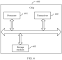
- FIG. 6 is a block diagram of a structure of an implementation of a chip according to this application.
- the chip shown in FIG. 6 may be a general-purpose processor, or may be a dedicated processor.
- a chip 600 includes a processor 601.
- the processor 601 may be configured to support the apparatus shown in FIG. 5 in performing the technical solution shown in FIG. 1, FIG. 2 , FIG. 3 , or FIG. 4 .
- the chip 600 may further include a transceiver 602.
- the transceiver 602 is configured to accept control of the processor 601, and is configured to support the apparatus shown in FIG. 5 in performing the technical solution shown in FIG. 1, FIG. 2 , FIG. 3 , or FIG. 4 .
- the chip 600 shown in FIG. 6 may further include a storage medium 603.
- the chip shown in FIG. 6 may be implemented by using the following circuit or device: one or more field programmable gate arrays (field programmable gate arrays, FPGAs), a programmable logic device (programmable logic device, PLD), an application-specific integrated circuit (application-specific integrated circuit, ASIC), or a system on chip (system on chip, SoC), a central processing unit (central processing unit, CPU), a network processor (network processor, NP), a digital signal processor (digital signal processor, DSP), a micro controller unit (micro controller unit, MCU), a controller, a state machine, gate logic, a discrete hardware component, any other suitable circuit, or any combination of circuits that can perform various functions described in this application.
- field programmable gate arrays field programmable gate arrays
- PLD programmable logic device
- ASIC application-specific integrated circuit
- SoC system on chip
- CPU central processing unit
- CPU central processing unit
- network processor network processor
- DSP digital signal processor
- micro controller unit micro controller unit
- steps in the foregoing methods can be implemented by using a hardware integrated logical circuit in the processor, or by using instructions in a form of software.
- the steps in the method disclosed with reference to embodiments of this application may be directly performed by a hardware processor, or may be performed by using a combination of hardware in the processor and a software module.
- a software module may be located in a mature storage medium in the art, such as a random access memory, a flash memory, a read-only memory, a programmable read-only memory, an electrically erasable programmable memory, or a register.
- the storage medium is located in the memory, and a processor reads information in the memory and completes the steps in the foregoing methods in combination with hardware of the processor. To avoid repetition, details are not described herein again.
- the processor in embodiments of this application may be an integrated circuit chip, and has a signal processing capability.
- steps in the foregoing method embodiments can be implemented by using a hardware integrated logical circuit in the processor, or by using instructions in a form of software.
- the processor may be a general purpose processor, a digital signal processor (DSP), an application-specific integrated circuit (ASIC), a field programmable gate array (FPGA) or another programmable logic device, a discrete gate or a transistor logic device, or a discrete hardware component.
- the processor may implement or perform the methods, steps, and logical block diagrams that are disclosed in embodiments of this application.
- the general-purpose processor may be a microprocessor, or the processor may be any conventional processor or the like.
- a software module may be located in a mature storage medium in the art, such as a random access memory, a flash memory, a read-only memory, a programmable read-only memory, an electrically erasable programmable memory, or a register.
- the storage medium is located in the memory, and a processor reads information in the memory and completes the steps in the foregoing methods in combination with hardware of the processor.
- the memory in embodiments of this application may be a volatile memory or a nonvolatile memory, or may include both a volatile memory and a nonvolatile memory.
- the nonvolatile memory may be a read-only memory (read-only memory, ROM), a programmable read-only memory (programmable ROM, PROM), an erasable programmable read-only memory (erasable PROM, EPROM), an electrically erasable programmable read-only memory (electrically EPROM, EEPROM), or a flash memory.
- the volatile memory may be a random access memory (random access memory, RAM), used as an external cache.
- RAM static random access memory
- SRAM static random access memory
- DRAM dynamic random access memory
- SDRAM synchronous dynamic random access memory
- double data rate SDRAM double data rate SDRAM
- ESDRAM enhanced synchronous dynamic random access memory
- synchlink dynamic random access memory synchlink DRAM, SLDRAM
- direct rambus RAM direct rambus RAM
- an embodiment of this application further provides a computer program product.
- the computer program product includes a computer program or instructions.
- the computer program or the instructions are run on a computer, the computer is enabled to perform the method in any one of embodiments shown in FIG. 1, FIG. 2 , FIG. 3 , or FIG. 4 .
- an embodiment of this application further provides a computer storage medium.
- the computer storage medium stores a computer program or instructions.
- the computer program or the instructions are run on a computer, the computer is enabled to perform the method in any one of embodiments shown in FIG. 1, FIG. 2 , FIG. 3 , or FIG. 4 .
- All or some of the foregoing embodiments may be implemented by using software, hardware, firmware, or any combination thereof.
- software is used to implement embodiments, all or some of embodiments may be implemented in a form of a computer program product.
- the computer program product includes one or more computer programs or instructions. When the computer program or the instructions are loaded and executed on the computer, the procedures or functions according to embodiments of this application are all or partially generated.
- the computer may be a general-purpose computer, a dedicated computer, a computer network, or other programmable apparatuses.
- the computer program or instructions may be stored in a computer-readable storage medium or may be transmitted from a computer-readable storage medium to another computer-readable storage medium.
- the computer program or instructions may be transmitted from a website, computer, server, or data center to another website, computer, server, or data center in a wired (for example, a coaxial cable, an optical fiber, or a digital subscriber line (digital subscriber line, DSL)) or wireless (for example, infrared, radio, or microwave) manner.
- the computer-readable storage medium may be any usable medium accessible by the computer, or a data storage device, for example, a server or a data center, integrating one or more usable media.
- the usable medium may be a magnetic medium (for example, a floppy disk, a hard disk, or a magnetic tape), an optical medium (for example, a high-density digital video disc (digital video disc, DVD)), a semiconductor medium (for example, a solid-state drive (solid state disc, SSD)), or the like.
- a magnetic medium for example, a floppy disk, a hard disk, or a magnetic tape
- an optical medium for example, a high-density digital video disc (digital video disc, DVD)
- a semiconductor medium for example, a solid-state drive (solid state disc, SSD)
- a component may be, but is not limited to, a process that runs on a processor, a processor, an object, an executable file, an execution thread, a program, and/or a computer.
- a computing device and an application that runs on the computing device may be components.
- One or more components may reside within a process and/or a thread of execution, and a component may be located on one computer and/or distributed between two or more computers.
- these components may be executed from various computer-readable media that store various data structures.
- the components may communicate by using a local and/or remote process and according to, for example, a signal having one or more data packets (for example, data from two components interacting with another component in a local system, a distributed system, and/or across a network such as the Internet interacting with other systems by using the signal).
- a signal having one or more data packets (for example, data from two components interacting with another component in a local system, a distributed system, and/or across a network such as the Internet interacting with other systems by using the signal).
- the disclosed system, apparatus, and method may be implemented in other manners.
- the described apparatus embodiment is merely an example.
- division into the modules is merely logical function division and may be other division in an actual implementation.
- a plurality of modules or components may be combined or integrated into another system, or some features may be ignored or not performed.
- the displayed or discussed mutual couplings or direct couplings or communication connections may be implemented through some interfaces.
- the indirect couplings or communication connections between the apparatuses or units may be implemented in electronic, mechanical, or other forms.
- modules described as separate parts may or may not be physically separate, and parts displayed as modules may or may not be physical units, may be located in one position, or may be distributed on a plurality of network units. Some or all of the units may be selected based on actual requirements to achieve the objectives of the solutions in embodiments.
- function modules in embodiments of this application may be integrated into one processing unit, each of the modules may exist alone physically, or two or more modules are integrated into one unit.
- the functions When the functions are implemented in the form of a software function unit and sold or used as an independent product, the functions may be stored in a computer-readable storage medium.
- the computer software product is stored in a storage medium, and includes several instructions for instructing a computer device (which may be a personal computer, a server, a network device) to perform all or some of the steps of the methods described in embodiments of this application.
- the foregoing storage medium includes any medium that can store program code, such as a USB flash drive, a removable hard disk, a read-only memory (read-only memory, ROM), a random access memory (random access memory, RAM), a magnetic disk, or an optical disc.
- program code such as a USB flash drive, a removable hard disk, a read-only memory (read-only memory, ROM), a random access memory (random access memory, RAM), a magnetic disk, or an optical disc.
- the image generation apparatus, the terminal device, the computer storage medium, the computer program product, and the chip provided in embodiments of this application are all configured to perform the methods provided above. Therefore, for beneficial effects that can be achieved by the image generation apparatus, the terminal device, the computer storage medium, the computer program product, and the chip, refer to the beneficial effects corresponding to the methods provided above. Details are not described herein again.
- Embodiments in this specification are all described in a progressive manner, for same or similar parts in embodiments, refer to these embodiments, and each embodiment focuses on a difference from other embodiments.
- embodiments of the image generation apparatus, the terminal device, the computer storage medium, the computer program product, and the chip are basically similar to the method embodiments, and therefore are described briefly. For related parts, refer to descriptions in the method embodiments.
Landscapes
- Engineering & Computer Science (AREA)
- Physics & Mathematics (AREA)
- General Physics & Mathematics (AREA)
- Theoretical Computer Science (AREA)
- Computer Graphics (AREA)
- Software Systems (AREA)
- Geometry (AREA)
- Computer Hardware Design (AREA)
- General Engineering & Computer Science (AREA)
- Multimedia (AREA)
- Signal Processing (AREA)
- Architecture (AREA)
- Computer Vision & Pattern Recognition (AREA)
- Radar, Positioning & Navigation (AREA)
- Remote Sensing (AREA)
- Processing Or Creating Images (AREA)
- Studio Devices (AREA)
Applications Claiming Priority (2)
| Application Number | Priority Date | Filing Date | Title |
|---|---|---|---|
| CN202010364283.3A CN111556255B (zh) | 2020-04-30 | 2020-04-30 | 图像生成方法及装置 |
| PCT/CN2021/087574 WO2021218649A1 (fr) | 2020-04-30 | 2021-04-15 | Procédé et dispositif de génération d'images |
Publications (2)
| Publication Number | Publication Date |
|---|---|
| EP4131933A1 true EP4131933A1 (fr) | 2023-02-08 |
| EP4131933A4 EP4131933A4 (fr) | 2023-10-25 |
Family
ID=72004301
Family Applications (1)
| Application Number | Title | Priority Date | Filing Date |
|---|---|---|---|
| EP21796787.6A Pending EP4131933A4 (fr) | 2020-04-30 | 2021-04-15 | Procédé et dispositif de génération d'images |
Country Status (4)
| Country | Link |
|---|---|
| US (1) | US12211144B2 (fr) |
| EP (1) | EP4131933A4 (fr) |
| CN (1) | CN111556255B (fr) |
| WO (1) | WO2021218649A1 (fr) |
Families Citing this family (5)
| Publication number | Priority date | Publication date | Assignee | Title |
|---|---|---|---|---|
| CN111556255B (zh) * | 2020-04-30 | 2021-10-01 | 华为技术有限公司 | 图像生成方法及装置 |
| CN112788244B (zh) * | 2021-02-09 | 2022-08-09 | 维沃移动通信(杭州)有限公司 | 拍摄方法、拍摄装置和电子设备 |
| CN112967201B (zh) * | 2021-03-05 | 2024-06-25 | 厦门美图之家科技有限公司 | 图像光照调节方法、装置、电子设备及存储介质 |
| CN117835066A (zh) * | 2022-09-27 | 2024-04-05 | 北京字跳网络技术有限公司 | 融合图像深度的双摄曝光参数的调整方法和装置 |
| CN118591043B (zh) * | 2024-07-29 | 2025-01-14 | 深圳市兆祺科技有限公司 | 一种led灯具的亮灯控制方法及装置 |
Family Cites Families (22)
| Publication number | Priority date | Publication date | Assignee | Title |
|---|---|---|---|---|
| US8686981B2 (en) * | 2010-07-26 | 2014-04-01 | Apple Inc. | Display brightness control based on ambient light angles |
| US11632520B2 (en) * | 2011-11-14 | 2023-04-18 | Aaron Chien | LED light has built-in camera-assembly to capture colorful digital-data under dark environment |
| CN104994371B (zh) * | 2015-06-25 | 2017-03-01 | 苏州佳世达光电有限公司 | 影像获取装置及影像调整方法 |
| US10102654B1 (en) | 2015-07-28 | 2018-10-16 | Cascade Technologies, Inc. | System and method for a scalable interactive image-based visualization environment of computational model surfaces |
| CN107438165A (zh) * | 2016-05-25 | 2017-12-05 | 鸿富锦精密电子(郑州)有限公司 | 具有自拍辅助功能的电子装置及自拍辅助方法 |
| CN106910247B (zh) * | 2017-03-20 | 2020-10-02 | 厦门黑镜科技有限公司 | 用于生成三维头像模型的方法和装置 |
| IT201700033593A1 (it) * | 2017-03-27 | 2018-09-27 | 3Dflow Srl | Metodo di generazione di un modello 3D basato su elaborazione Structure from Motion e stereo fotometrico di immagini 2D sparse |
| US10210664B1 (en) | 2017-05-03 | 2019-02-19 | A9.Com, Inc. | Capture and apply light information for augmented reality |
| CN109242947B (zh) | 2017-07-11 | 2023-07-21 | 中慧医学成像有限公司 | 三维超声图像显示方法 |
| CN107506714B (zh) * | 2017-08-16 | 2021-04-02 | 成都品果科技有限公司 | 一种人脸图像重光照的方法 |
| KR102370763B1 (ko) * | 2017-09-26 | 2022-03-04 | 삼성전자주식회사 | 외부 광에 기반하여 카메라를 제어하는 전자 장치 및 제어 방법 |
| CN107566751B (zh) | 2017-09-30 | 2019-11-26 | 北京金山安全软件有限公司 | 图像处理方法、装置、电子设备及介质 |
| CN107580209B (zh) * | 2017-10-24 | 2020-04-21 | 维沃移动通信有限公司 | 一种移动终端的拍照成像方法及装置 |
| US10643375B2 (en) * | 2018-02-26 | 2020-05-05 | Qualcomm Incorporated | Dynamic lighting for objects in images |
| CN108537870B (zh) * | 2018-04-16 | 2019-09-03 | 太平洋未来科技(深圳)有限公司 | 图像处理方法、装置及电子设备 |
| CN108573480B (zh) * | 2018-04-20 | 2020-02-11 | 太平洋未来科技(深圳)有限公司 | 基于图像处理的环境光补偿方法、装置及电子设备 |
| CN108682050B (zh) | 2018-08-16 | 2020-03-24 | Oppo广东移动通信有限公司 | 基于三维模型的美颜方法和装置 |
| CN109304866A (zh) * | 2018-09-11 | 2019-02-05 | 魏帅 | 使用3d摄像头自助拍照打印3d人像的一体设备及方法 |
| CN109325437B (zh) * | 2018-09-17 | 2021-06-22 | 北京旷视科技有限公司 | 图像处理方法、装置和系统 |
| CN109447931B (zh) * | 2018-10-26 | 2022-03-15 | 深圳市商汤科技有限公司 | 图像处理方法及装置 |
| CN113206921B (zh) * | 2020-01-31 | 2024-02-27 | 株式会社美迪特 | 外部光干扰去除方法 |
| CN111556255B (zh) | 2020-04-30 | 2021-10-01 | 华为技术有限公司 | 图像生成方法及装置 |
-
2020
- 2020-04-30 CN CN202010364283.3A patent/CN111556255B/zh active Active
-
2021
- 2021-04-15 WO PCT/CN2021/087574 patent/WO2021218649A1/fr not_active Ceased
- 2021-04-15 US US17/922,246 patent/US12211144B2/en active Active
- 2021-04-15 EP EP21796787.6A patent/EP4131933A4/fr active Pending
Also Published As
| Publication number | Publication date |
|---|---|
| EP4131933A4 (fr) | 2023-10-25 |
| CN111556255A (zh) | 2020-08-18 |
| CN111556255B (zh) | 2021-10-01 |
| US12211144B2 (en) | 2025-01-28 |
| US20230177768A1 (en) | 2023-06-08 |
| WO2021218649A1 (fr) | 2021-11-04 |
Similar Documents
| Publication | Publication Date | Title |
|---|---|---|
| US12211144B2 (en) | Image generation method and apparatus | |
| US11436779B2 (en) | Image processing method, electronic device, and storage medium | |
| US10067562B2 (en) | Display apparatus and image correction method thereof | |
| US20190244369A1 (en) | Display device and method for image processing | |
| US11263483B2 (en) | Method and apparatus for recognizing image and storage medium | |
| CN110780742B (zh) | 眼球追踪处理方法及相关装置 | |
| US10848669B2 (en) | Electronic device and method for displaying 360-degree image in the electronic device | |
| US20220351469A1 (en) | Simulation Object Identity Recognition Method, Related Apparatus, and System | |
| US20150243063A1 (en) | Method and apparatus for displaying biometric information | |
| WO2018121385A1 (fr) | Procédé et appareil de traitement d'informations, et support de stockage informatique | |
| US20200402321A1 (en) | Method, electronic device and storage medium for image generation | |
| WO2022021631A1 (fr) | Procédé de commande d'interaction, dispositif terminal, et support de stockage | |
| CN114255204A (zh) | 弱视训练方法、装置、设备及存储介质 | |
| CN108632543A (zh) | 图像显示方法、装置、存储介质及电子设备 | |
| CN109379539A (zh) | 一种屏幕补光方法及终端 | |
| CN105867858A (zh) | 控制方法、控制装置及电子装置 | |
| US9536133B2 (en) | Display apparatus and control method for adjusting the eyes of a photographed user | |
| US20240207021A1 (en) | Wireless scanning system and method for paring wireless scanning system | |
| CN114758601A (zh) | 屏幕显示颜色调整方法及电子设备 | |
| CN114168096B (zh) | 输出画面的显示方法、系统、移动终端以及存储介质 | |
| US8755819B1 (en) | Device location determination using images | |
| CN109345623B (zh) | 模型校验方法及服务器、计算机存储介质 | |
| KR20160008357A (ko) | 영상 통화 방법 및 장치 | |
| US12542978B2 (en) | Image light supplementation method and electronic device | |
| US20250374003A1 (en) | Electronic apparatus and controlling method thereof |
Legal Events
| Date | Code | Title | Description |
|---|---|---|---|
| STAA | Information on the status of an ep patent application or granted ep patent |
Free format text: STATUS: THE INTERNATIONAL PUBLICATION HAS BEEN MADE |
|
| PUAI | Public reference made under article 153(3) epc to a published international application that has entered the european phase |
Free format text: ORIGINAL CODE: 0009012 |
|
| STAA | Information on the status of an ep patent application or granted ep patent |
Free format text: STATUS: REQUEST FOR EXAMINATION WAS MADE |
|
| 17P | Request for examination filed |
Effective date: 20221031 |
|
| AK | Designated contracting states |
Kind code of ref document: A1 Designated state(s): AL AT BE BG CH CY CZ DE DK EE ES FI FR GB GR HR HU IE IS IT LI LT LU LV MC MK MT NL NO PL PT RO RS SE SI SK SM TR |
|
| DAV | Request for validation of the european patent (deleted) | ||
| DAX | Request for extension of the european patent (deleted) | ||
| REG | Reference to a national code |
Ref country code: DE Ref legal event code: R079 Free format text: PREVIOUS MAIN CLASS: H04N0005265000 Ipc: G06T0015500000 |
|
| A4 | Supplementary search report drawn up and despatched |
Effective date: 20230927 |
|
| RIC1 | Information provided on ipc code assigned before grant |
Ipc: G06T 19/20 20110101ALI20230921BHEP Ipc: G06T 17/00 20060101ALI20230921BHEP Ipc: G06T 15/50 20110101AFI20230921BHEP |