EP4131944A1 - Dispositif de commande d'affichage, procédé de commande d'affichage et programme - Google Patents
Dispositif de commande d'affichage, procédé de commande d'affichage et programme Download PDFInfo
- Publication number
- EP4131944A1 EP4131944A1 EP20928004.9A EP20928004A EP4131944A1 EP 4131944 A1 EP4131944 A1 EP 4131944A1 EP 20928004 A EP20928004 A EP 20928004A EP 4131944 A1 EP4131944 A1 EP 4131944A1
- Authority
- EP
- European Patent Office
- Prior art keywords
- image data
- display
- extracted
- image
- vehicle
- Prior art date
- Legal status (The legal status is an assumption and is not a legal conclusion. Google has not performed a legal analysis and makes no representation as to the accuracy of the status listed.)
- Pending
Links
- 238000000034 method Methods 0.000 title claims description 60
- 238000001514 detection method Methods 0.000 claims abstract description 51
- 230000008859 change Effects 0.000 claims description 38
- 230000004044 response Effects 0.000 claims description 6
- 230000008569 process Effects 0.000 description 51
- 238000010586 diagram Methods 0.000 description 12
- 238000006243 chemical reaction Methods 0.000 description 9
- 238000004891 communication Methods 0.000 description 6
- 239000000284 extract Substances 0.000 description 6
- 230000001133 acceleration Effects 0.000 description 5
- 230000006835 compression Effects 0.000 description 2
- 238000007906 compression Methods 0.000 description 2
- 230000000694 effects Effects 0.000 description 2
- 238000005401 electroluminescence Methods 0.000 description 2
- 230000006870 function Effects 0.000 description 2
- 230000008901 benefit Effects 0.000 description 1
- 239000000470 constituent Substances 0.000 description 1
- 238000003384 imaging method Methods 0.000 description 1
- 239000004973 liquid crystal related substance Substances 0.000 description 1
- 230000003287 optical effect Effects 0.000 description 1
- 239000013307 optical fiber Substances 0.000 description 1
- 239000004065 semiconductor Substances 0.000 description 1
Images


Classifications
-
- H—ELECTRICITY
- H04—ELECTRIC COMMUNICATION TECHNIQUE
- H04N—PICTORIAL COMMUNICATION, e.g. TELEVISION
- H04N7/00—Television systems
- H04N7/18—Closed-circuit television [CCTV] systems, i.e. systems in which the video signal is not broadcast
- H04N7/181—Closed-circuit television [CCTV] systems, i.e. systems in which the video signal is not broadcast for receiving images from a plurality of remote sources
-
- B—PERFORMING OPERATIONS; TRANSPORTING
- B60—VEHICLES IN GENERAL
- B60R—VEHICLES, VEHICLE FITTINGS, OR VEHICLE PARTS, NOT OTHERWISE PROVIDED FOR
- B60R1/00—Optical viewing arrangements; Real-time viewing arrangements for drivers or passengers using optical image capturing systems, e.g. cameras or video systems specially adapted for use in or on vehicles
- B60R1/20—Real-time viewing arrangements for drivers or passengers using optical image capturing systems, e.g. cameras or video systems specially adapted for use in or on vehicles
- B60R1/22—Real-time viewing arrangements for drivers or passengers using optical image capturing systems, e.g. cameras or video systems specially adapted for use in or on vehicles for viewing an area outside the vehicle, e.g. the exterior of the vehicle
- B60R1/23—Real-time viewing arrangements for drivers or passengers using optical image capturing systems, e.g. cameras or video systems specially adapted for use in or on vehicles for viewing an area outside the vehicle, e.g. the exterior of the vehicle with a predetermined field of view
- B60R1/26—Real-time viewing arrangements for drivers or passengers using optical image capturing systems, e.g. cameras or video systems specially adapted for use in or on vehicles for viewing an area outside the vehicle, e.g. the exterior of the vehicle with a predetermined field of view to the rear of the vehicle
-
- B—PERFORMING OPERATIONS; TRANSPORTING
- B60—VEHICLES IN GENERAL
- B60R—VEHICLES, VEHICLE FITTINGS, OR VEHICLE PARTS, NOT OTHERWISE PROVIDED FOR
- B60R1/00—Optical viewing arrangements; Real-time viewing arrangements for drivers or passengers using optical image capturing systems, e.g. cameras or video systems specially adapted for use in or on vehicles
- B60R1/20—Real-time viewing arrangements for drivers or passengers using optical image capturing systems, e.g. cameras or video systems specially adapted for use in or on vehicles
- B60R1/22—Real-time viewing arrangements for drivers or passengers using optical image capturing systems, e.g. cameras or video systems specially adapted for use in or on vehicles for viewing an area outside the vehicle, e.g. the exterior of the vehicle
- B60R1/28—Real-time viewing arrangements for drivers or passengers using optical image capturing systems, e.g. cameras or video systems specially adapted for use in or on vehicles for viewing an area outside the vehicle, e.g. the exterior of the vehicle with an adjustable field of view
-
- G—PHYSICS
- G09—EDUCATION; CRYPTOGRAPHY; DISPLAY; ADVERTISING; SEALS
- G09G—ARRANGEMENTS OR CIRCUITS FOR CONTROL OF INDICATING DEVICES USING STATIC MEANS TO PRESENT VARIABLE INFORMATION
- G09G5/00—Control arrangements or circuits for visual indicators common to cathode-ray tube indicators and other visual indicators
- G09G5/36—Control arrangements or circuits for visual indicators common to cathode-ray tube indicators and other visual indicators characterised by the display of a graphic pattern, e.g. using an all-points-addressable [APA] memory
- G09G5/39—Control of the bit-mapped memory
- G09G5/391—Resolution modifying circuits, e.g. variable screen formats
-
- H—ELECTRICITY
- H04—ELECTRIC COMMUNICATION TECHNIQUE
- H04N—PICTORIAL COMMUNICATION, e.g. TELEVISION
- H04N23/00—Cameras or camera modules comprising electronic image sensors; Control thereof
- H04N23/60—Control of cameras or camera modules
-
- H—ELECTRICITY
- H04—ELECTRIC COMMUNICATION TECHNIQUE
- H04N—PICTORIAL COMMUNICATION, e.g. TELEVISION
- H04N23/00—Cameras or camera modules comprising electronic image sensors; Control thereof
- H04N23/90—Arrangement of cameras or camera modules, e.g. multiple cameras in TV studios or sports stadiums
-
- H—ELECTRICITY
- H04—ELECTRIC COMMUNICATION TECHNIQUE
- H04N—PICTORIAL COMMUNICATION, e.g. TELEVISION
- H04N5/00—Details of television systems
- H04N5/222—Studio circuitry; Studio devices; Studio equipment
- H04N5/262—Studio circuits, e.g. for mixing, switching-over, change of character of image, other special effects ; Cameras specially adapted for the electronic generation of special effects
- H04N5/2628—Alteration of picture size, shape, position or orientation, e.g. zooming, rotation, rolling, perspective, translation
-
- B—PERFORMING OPERATIONS; TRANSPORTING
- B60—VEHICLES IN GENERAL
- B60R—VEHICLES, VEHICLE FITTINGS, OR VEHICLE PARTS, NOT OTHERWISE PROVIDED FOR
- B60R2300/00—Details of viewing arrangements using cameras and displays, specially adapted for use in a vehicle
- B60R2300/30—Details of viewing arrangements using cameras and displays, specially adapted for use in a vehicle characterised by the type of image processing
- B60R2300/306—Details of viewing arrangements using cameras and displays, specially adapted for use in a vehicle characterised by the type of image processing using a re-scaling of images
-
- B—PERFORMING OPERATIONS; TRANSPORTING
- B60—VEHICLES IN GENERAL
- B60R—VEHICLES, VEHICLE FITTINGS, OR VEHICLE PARTS, NOT OTHERWISE PROVIDED FOR
- B60R2300/00—Details of viewing arrangements using cameras and displays, specially adapted for use in a vehicle
- B60R2300/30—Details of viewing arrangements using cameras and displays, specially adapted for use in a vehicle characterised by the type of image processing
- B60R2300/307—Details of viewing arrangements using cameras and displays, specially adapted for use in a vehicle characterised by the type of image processing virtually distinguishing relevant parts of a scene from the background of the scene
-
- B—PERFORMING OPERATIONS; TRANSPORTING
- B60—VEHICLES IN GENERAL
- B60R—VEHICLES, VEHICLE FITTINGS, OR VEHICLE PARTS, NOT OTHERWISE PROVIDED FOR
- B60R2300/00—Details of viewing arrangements using cameras and displays, specially adapted for use in a vehicle
- B60R2300/70—Details of viewing arrangements using cameras and displays, specially adapted for use in a vehicle characterised by an event-triggered choice to display a specific image among a selection of captured images
Definitions
- the present invention relates to a display control apparatus, a display control method, and a program.
- Patent Literature 1 images from rear and side regions of a vehicle body are displayed in two parts of a monitor screen while using mutually-different compression rates, and the compression rates are varied in accordance with vehicle information.
- Patent Literature 1 Japanese Unexamined Patent Application Publication No. 2016-048839
- the present embodiments are to provide a display control apparatus and the like capable of suitably displaying images captured by one or more cameras.
- a display control apparatus includes a captured data acquisition unit, a motion state detection unit, an extracted image data generation unit, a display image data generation unit, and an output unit.
- the captured data acquisition unit is configured to acquire captured data obtained by a camera capturing scenery outside a vehicle.
- the motion state detection unit is configured to detect a motion state of the vehicle.
- the extracted image data generation unit is configured to generate an extracted image from an image related to the captured data by using an angle of view set in accordance with the motion state.
- the display image data generation unit is configured to generate display image data related to a display image having a preset image size, from extracted image data.
- the output unit is configured to output the display image data to a display unit having the image size.
- a display control method includes a captured data acquisition step, a motion state detection step, an extracted image data generation step, a display image data generation step, and an output step.
- the captured data acquisition step is configured to acquire captured data obtained by a camera capturing scenery outside a vehicle.
- the motion state detection step is configured to detect a motion state of the vehicle.
- the extracted image data generation step is configured to generate an extracted image from an image related to the captured data by using an angle of view set in accordance with the motion state.
- the display image data generation step is configured to generate display image data related to a display image having a preset image size, from extracted image data.
- the output step is configured to output the display image data to a display unit having the image size.
- a program is for causing a computer to implement a display control method, the display control method including a captured data acquisition step, a motion state detection step, an extracted image data generation step, a display image data generation step, and an output step.
- the captured data acquisition step is configured to acquire captured data obtained by a camera capturing scenery outside a vehicle.
- the motion state detection step is configured to detect a motion state of the vehicle.
- the extracted image data generation step is configured to generate an extracted image from an image related to the captured data by using an angle of view set in accordance with the motion state.
- the display image data generation step is configured to generate display image data related to a display image having a preset image size, from extracted image data.
- the output step is configured to output the display image data to a display unit having the image size.
- the display control apparatus and the like capable of suitably displaying the images captured by the camera.
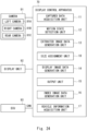
- FIG. 1 is a block diagram of the display control apparatus according to the first embodiment.
- a display control apparatus 10 shown in Fig. 1 is connected to a camera 91 and to a display unit 92.
- the display control apparatus 10, the camera 91, and the display unit 92 are installed in a vehicle.
- the camera 91 is installed in an arbitrary position of the vehicle and captures scenery outside the vehicle so as to generate captured data which is data of captured images.
- the camera 91 generates captured data having 30 frames per second (30 fps), for example, and supplies the generated captured data to the display control apparatus 10 every 1/30 of a second.
- the captured data may be generated by using a format of H.264 or H.265, for example.
- the camera 91 may include a plurality of cameras.
- the camera 91 in the present embodiment includes a left camera 91A, a right camera 91B, and a rear camera 91C.
- the left camera 91A, the right camera 91B, and the rear camera 91C are each an imaging apparatus including an objective lens, an image pickup element, an Analog-to-Digital (A-D) conversion element, and the like.
- the left camera 91A, the right camera 91B, and the rear camera 91C each generate captured data and supply the generated captured data to the display control apparatus 10.
- the display unit 92 is a display unit provided so as to be able to present information to a driver and includes a display part such as a liquid crystal panel or an organic electroluminescence (EL) panel, for example.
- the display unit 92 is installed in such a position (e.g., on a dashboard) that the driver is able to visually recognize the display part.
- the display unit 92 receives image data from the display control apparatus 10 and displays images related to the received image data on the display part.
- the display control apparatus 10 includes a computation apparatus such as a Central Processing Unit (CPU) or a Micro Controller Unit (MCU), for example. Further, in addition to the computation apparatus, the display control apparatus 10 includes, at least, a control board structured with a non-volatile or volatile memory such as a flash memory or a Dynamic Random Access Memory (DRAM) and one or more other electrical circuits.
- the display control apparatus 10 has a program installed in any of these elements such as the computation apparatus and realizes the functions described below by using a combination of software or hardware.
- the display control apparatus 10 processes the image data related to the images captured by the camera 91 and outputs prescribed image data having been processed to the display unit 92.
- the display control apparatus 10 includes, as primary constituent elements thereof, a captured data acquisition unit 11, a motion state detection unit 12, an extracted image data generation unit 13, a display image data generation unit 14, and an output unit 15. These elements included in the display control apparatus 10 are communicably connected together by a communication bus.
- the captured data acquisition unit 11 acquires the captured data generated as a result of the camera 91 capturing the scenery outside the vehicle.
- the captured data acquisition unit 11 supplies the acquired captured data to the extracted image data generation unit 13 via the communication bus.
- the motion state detection unit 12 detects a motion state of the vehicle and generates motion state information corresponding to the motion state.
- the "motion state of the vehicle” denotes a state of motion related to traveling of the vehicle.
- the motion state of the vehicle may be, for example, a traveling direction of the vehicle or a traveling speed of the vehicle.
- the motion state detection unit 12 may analyze images related to the captured data acquired by the captured data acquisition unit 11, so as to detect the motion state of the vehicle based on changes in the position of an object included in the analyzed images.
- the motion state detection unit 12 supplies the motion state information generated in the manner described above, to the extracted image data generation unit 13.
- the motion state detection unit 12 may connect to an acceleration sensor (not shown), for example, so as to detect the motion state of the vehicle based on changes in acceleration obtained from the acceleration sensor.
- the motion state detection unit 12 may connect to a positioning information reception unit (not shown) that receives positioning information for positioning the location of the host vehicle from a satellite positioning system such as a Global Navigation Satellite System (GNSS), so as to detect the motion state of the vehicle based on changes in position information obtained from the positioning information reception unit.
- GNSS Global Navigation Satellite System
- the extracted image data generation unit 13 receives the captured data from the captured data acquisition unit 11. Further, the extracted image data generation unit 13 receives the motion state information from the motion state detection unit 12 and determines an angle of view used for generating an extracted image based on the received motion state information. More specifically, the extracted image data generation unit 13 according to the present embodiment sets the angle of view corresponding to a traveling speed of the vehicle. For example, the extracted image data generation unit 13 sets a first angle of view corresponding to the traveling speed at a first speed so as to be narrower than a second angle of view corresponding to a second speed lower than the first speed.
- the extracted image data generation unit 13 extracts, from the captured data, an image having the angle of view determined as described above and generates extracted image data related to an image of an extracted region (an extracted image). In this manner, the extracted image data generation unit 13 has generated the extracted image from the captured data by using the angle of view set in accordance with the motion state of the vehicle. The extracted image data generation unit 13 supplies the generated extracted image data to the display image data generation unit 14.
- the display image data generation unit 14 receives the extracted image data from the extracted image data generation unit 13 and generates display image data by using the received extracted image data.
- the display image data is image data to be output to the display unit 92 and corresponds to an image size of the display part included in the display unit 92.
- the "image size of the display part" denotes the image size of the region.
- the display image data generation unit 14 generates the display image data obtained by converting the extracted image so as to have the preset image size. Examples of processes that can be performed by the display image data generation unit 14 on the extracted image include enlarging, reducing, expanding, compressing, noise removal, and tone correction.
- the display image data generation unit 14 supplies the generated display image to the output unit 15.
- a specific aspect of the method for enlarging or reducing the image may be expanding or compressing the image.
- expanding the image denotes stretching the image along one prescribed direction. In that situation, for the pixels in the stretching direction, the intervals between the pixels are widened, and the pixels therebetween are interpolated.
- compressing the image denotes shrinking the image along one prescribed direction. In that situation, for the pixels in the shrinking direction, the intervals between the pixels are shortened, and pixels are interpolated as appropriate.
- the output unit 15 is an interface for communicably connecting the display control apparatus 10 and the display unit 92 to each other.
- the output unit 15 outputs the display image to the display unit 92 having the preset image size.
- FIG. 2 is a top view showing the captured ranges of the cameras on the vehicle having the display control apparatus according to the first embodiment installed therein.
- a vehicle 90 in Fig. 2 is an automobile and serves as an embodiment of a mobile body.
- the vehicle 90 has the three cameras explained with reference to Fig. 1 , namely, the left camera 91A, the right camera 91B, and the rear camera 91C.
- the left camera 91A is installed on the left face of the vehicle 90 and captures scenery on the left side of the vehicle 90.
- a capture angle of view A10 in the horizontal direction indicated by the two-dot chain line is 180 degrees.
- images captured by the left camera 91A include the scenery at the angle of view of 180 degrees on the left side of the vehicle 90.
- the right camera 91B is installed on the right face of the vehicle 90 and captures scenery on the right side of the vehicle 90.
- a capture angle of view B10 in the horizontal direction is 180 degrees.
- the rear camera 91C is installed on the rear face of the vehicle 90 and captures scenery on the rear side of the vehicle 90.
- a capture angle of view C10 in the horizontal direction is 180 degrees.
- an angle of view in the horizontal direction or a horizontal angle of view may simply be referred to as an "angle of view”.
- the solid lines extending radially from the left camera 91A toward the left rear of the vehicle 90 indicate an angle of view A11 and an angle of view A12 wider than the angle of view A11 of an extracted image extracted from the captured images of the left camera 91A.
- the extracted image data generation unit 13 sets the first angle of view corresponding to the traveling speed at the first speed to the angle of view A 11 and sets the second angle of view corresponding to the second speed lower than the first speed to the angle of view A12.
- the solid line extending radially from the right camera 91B toward the right rear of the vehicle 90 indicates an angle of view B11 of an extracted image extracted from the captured images of the right camera 91B.
- the solid line extending radially from the rear camera 91C toward the rear of the vehicle 90 indicates an angle of view C11 of an extracted image extracted from the captured images of the rear camera 91C.
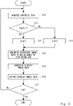
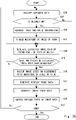
- Fig. 3 is a flowchart of the display control apparatus 10 according to the first embodiment.
- the flowchart shown in Fig. 3 indicates processes performed on the left camera 91A by the display control apparatus 10 installed in the vehicle 90 shown in Fig. 2 .
- the flowchart in Fig. 3 is started, for example, when a primary system of the vehicle 90 starts up.
- the captured data acquisition unit 11 of the display control apparatus 10 acquires the captured data from the left camera 91A (step S10). After that, as a motion state of the vehicle 90, the motion state detection unit 12 of the display control apparatus 10 determines whether or not a traveling speed V of the vehicle 90 is equal to or higher than a threshold value Vth (step S 11). When it is determined that the traveling speed V of the vehicle 90 is equal to or higher than the threshold value Vth (step S11: Yes), the display control apparatus 10 proceeds to step S12. On the contrary, when it is not determined that the traveling speed V of the vehicle 90 is equal to or higher than the threshold value Vth (step S11: No), the display control apparatus 10 proceeds to step S13.
- step S12 the extracted image data generation unit 13 of the display control apparatus 10 sets an angle of view A of the extracted image to the angle of view A11 (step S12). After that, the display control apparatus 10 proceeds to step S14.
- step S13 the extracted image data generation unit 13 of the display control apparatus 10 sets the angle of view A of the extracted image to the angle of view A12 (step S13). After that, the display control apparatus 10 proceeds to step S14.
- the threshold value Vth serves as a condition used by the extracted image data generation unit 13 for setting the angle of view. Further, depending on weather statuses, the threshold value Vth may arbitrarily be changed through a terminal apparatus (not shown) connected to the display control apparatus 10.
- step S14 the extracted image data generation unit 13 of the display control apparatus 10 generates extracted image data by using the set angle of view (step S14).
- the extracted image data generation unit 13 when the traveling speed V of the vehicle is equal to or higher than the threshold value Vth, the extracted image data generation unit 13 generates the extracted image data related to the extracted image having the angle of view A11.
- the extracted image data generation unit 13 when the traveling speed V of the vehicle is not equal to or higher than the threshold value Vth, the extracted image data generation unit 13 generates the extracted image data related to the extracted image having the angle of view A12 that is wider than the angle of view A11.
- the extracted image data generation unit 13 supplies the generated extracted image data to the display image data generation unit 14.
- the display image data generation unit 14 of the display control apparatus 10 generates display image data from the extracted image data received from the extracted image data generation unit 13 (step S15) and supplies the generated display image data to the output unit 15. More specifically, when the traveling speed is equal to or higher than the threshold value Vth, the display image data is generated while keeping the image size thereof. On the contrary, when the traveling speed is not equal to or higher than the threshold value Vth, the display image data is generated by compressing the image thereof.
- the output unit 15 of the display control apparatus 10 outputs the display image data received from the display image data generation unit 14 to the display unit 92 (step S16).
- the display control apparatus 10 determines whether or not the series of processes is to be ended (step S17). Examples of situations where the series of processes is ended include when the system is stopped and when the processes are ended according to an operation performed by the driver. When it is not determined that the series of processes is to be ended (step S17: No), the display control apparatus 10 returns to step S10 and continues the processes. When it is determined that the series of processes is to be ended (step S17: Yes), the display control apparatus 10 ends the processes.
- the display control apparatus 10 sets the angle of view of the extracted image in accordance with the traveling speed of the vehicle 90.
- the processes for the left camera 91A were used as an example.
- the processes described above are applicable to processes of the right camera 91B or the rear camera 91C.
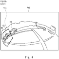
- FIG. 4 is a drawing showing a first example of the images captured by the left camera 91A.
- An image P10 shown in Fig. 4 is obtained as a result of the left camera 91A capturing scenery on the left side of the vehicle 90.
- the right side of the image P10 shows scenery on the left front of the vehicle 90, whereas the left side of the image P10 shows scenery on the left rear of the vehicle 90.
- On the right side of the image P10 a truck and a motorcycle are captured. In other words, on the left front of the vehicle 90, the truck and the motorcycle are present.
- a border T11 of the extracted image is indicated by a bold two-dot chain line.
- the extracted image corresponds to the region enclosed by the border T11.
- the border T11 represents the extracted image related to the angle of view A11 described above.
- the extracted image data generation unit 13 sets the angle of view A11 because the traveling speed V of the vehicle 90 is equal to or higher than Vth and further extracts the region indicated by the border T11.
- the region enclosed by the border T11 contains the other vehicles H1 and H2. Accordingly, the extracted image contains the other vehicles H1 and H2.
- the border T11 shown in Fig. 4 is distorted so as to correspond to the lens distortion which the image P10 has.
- the display image data generation unit 14 processes the extracted image so that the border T11 becomes rectangular, while the image size becomes equal to an image size of a display image (explained later).
- Fig. 5 is a drawing showing a first example of the display image displayed on the display unit according to the first embodiment.
- Fig. 5 shows a display image P100.
- the display image P100 includes a left display image P11, a rear display image P12, and a right display image P13.
- the left display image P11 is an image generated from the captured data of the left camera 91A.
- the rear display image P12 is an image generated from the captured data of the rear camera 91C.
- the right display image P13 is an image generated from the captured data of the right camera 91B.
- the display image P100 displays the images arranged side by side resulting from the extracted image data generation unit 13 extracting data, as appropriate, from the pieces of captured data respectively generated by the left camera 91A, the right camera 91B, and the rear camera 91C and further the display image data generation unit 14 processing the data as the display images.
- the left display image P11 is displayed in a region having a width W11.
- the rear display image P12 is displayed in another region having a width W12.
- the right display image P13 is displayed in yet another region having a width W13.
- the left display image P11 shown in Fig. 5 was generated from the extracted image data extracted by the border T11 shown in Fig. 4 . Accordingly, the left display image P11 contains the other vehicles H1 and H2. As shown in the drawing, from the extracted image data having the lens distortion, the display image data generation unit 14 has generated the left display image P11 as an image having substantially no distortion. As described herein, the display image data generation unit 14 generates and displays the left display image P11, the rear display image P12, and the right display image P13 included in the display image P100, as the images in the state of having substantially no distortion, from the respective pieces of captured data.
- FIG. 6 is a drawing showing a second example of the images captured by the left camera.
- the image P10 shown in Fig. 6 is obtained as a result of the left camera 91A capturing scenery on the left side of the vehicle 90.
- a border T12 related to an extracted image is different from the border T11 shown in Fig. 4 .
- the border T12 On the left side of the image P10 shown in Fig. 6 , the border T12 is indicated by a bold two-dot chain line.
- the border T12 represents the extracted image related to the angle of view A12 described above.
- the extracted image data generation unit 13 sets the angle of view A12 because the traveling speed V of the vehicle 90 is lower than Vth and further extracts the region indicated by the border T12.
- the angle of view A12 is wider than the angle of view A11. Accordingly, the region enclosed by the border T12 contains the other vehicle H3, in addition to the other vehicles H1 and H2.
- the extracted image contains the other vehicles H1 to H3.
- the display image data generation unit 14 processes the extracted image so that the border T12 becomes rectangular, while the image size becomes equal to an image size of a display image (explained later).
- Fig. 7 is a drawing showing a second example of the display image displayed on the display unit according to the first embodiment.
- Fig. 7 shows a display image P101.
- the display image P101 is different from the image P100 shown in Fig. 5 for including a left display image P14 in place of the left display image P11.
- differences from the image P100 will primarily be explained.
- the left display image P14 shown in Fig. 7 was generated from the extracted image data extracted by the border T12 shown in Fig. 6 . Accordingly, the left display image P14 contains the other vehicle H3 in addition to the other vehicles H1 and H2. Further, the width W11 with which the left display image P14 is displayed is the same as the width W11 of the left display image P11 shown in Fig. 5 . In other words, the left display image P14 displays the image related to the angle of view A12 wider than the angle of view A11, while using the same width as the image related to the angle of view A11. Accordingly, when the left display image P11 is compared with the left display image P14, the width of the left display image P14 is relatively shrunk along the left-and-right direction.
- the display control apparatus 10 is capable of displaying the image of the wider range, without the need to enlarge the area of the display part. Consequently, the display control apparatus 10 is able to suitably assist driving of the user.
- the captured data of the left camera 91A was used as an example.
- the configuration described above is also applicable to the right camera 91B and the rear camera 91C.
- the display control apparatus 10 according to the present embodiment includes the abovementioned three types of cameras as the camera 91, the number of cameras may be one or more.
- the camera 91 in the above example includes a fisheye lens, the image related to the captured data has the lens distortion.
- possible examples of the images captured by the camera 91 are not limited to those described above, and the images do not necessarily have to have distortion.
- the abovementioned relationship between the traveling speed V of the vehicle and the angle of view A is merely an example. As long as the angle of view related to the extracted image data is set in accordance with the motion state of the vehicle, possible relationships between the traveling speed V and the angle of view A are not limited to the relationship described above.
- the display image data generation unit 14 may display the extracted image related to the extracted image data after rotating the image by 90 degrees with respect to the display part. For example, converting the extracted image into a display image as the left display image P14 without rotation will be referred to as a first conversion. In contrast, converting the extracted image into a display image as the left display image P14 with the rotation of 90 degrees will be referred to as a second conversion. In that situation, when the distortion of the image related to the first conversion is larger than the distortion of the image related to the second conversion, the display image data generation unit 14 may generate the display image by converting the extracted image with the second conversion. With this configuration, the display control apparatus 10 is able to display the image that is less distorted and has a suitable angle of view.
- the display control apparatus 10 By displaying the image shrunk along the left-and-right direction, the display control apparatus 10 according to the first embodiment is configured to display the image having a wider angle of view than in the situations without the shrinkage. Consequently, according to the first embodiment, it is possible to provide the display control apparatus and the like capable of suitably displaying the images captured by the cameras.
- FIG. 8 is a block diagram of the display control apparatus according to the second embodiment.
- a display control apparatus 20 shown in Fig. 8 includes an index image data generation unit 16.
- the index image data generation unit 16 acquires a distortion state of a display image generated by the display image data generation unit 14 and further generates an index image corresponding to the acquired distortion state.
- the "index image data” denotes data of the "index image” indicating a distorted state of the display image included in the display image data.
- the index image is configured so as to be able to be compared with an image in the situation where the display image data generation unit 14 has generated the image without any distortion.
- the index image data generation unit 16 generates the index image data including the index image for expressing the distortion of the display image. Further, the index image data generation unit 16 supplies the generated index image data to the display image data generation unit 14. Further, the display image data generation unit 14 generates display image data in which the index image data received from the index image data generation unit 16 is superimposed.
- FIG. 9 is a drawing showing an example of a display image according to the second embodiment.
- An image P102 shown in Fig. 9 is obtained by superimposing index images onto the image P101 shown in Fig. 7 .
- an index image G14 is superimposed.
- an index image G12 is superimposed.
- an index image G13 is superimposed.
- the index image G12 and the index image G13 each have a circular shape. It means that the rear display image P12 related to the index image G12 is not distorted and that the rear display image P13 related to the index image G13 is not distorted.
- the index image G14 has a vertically elongated oval shape of which the dimension in the up-and-down direction is relatively long, while the dimension in the left-and-right direction is relatively short. Further, the dimension of the oval in the up-and-down direction is equal to that of each of the index images G12 and G13.
- the index image G14 has a shape relatively shrunk along the left-and-right direction, as compared to the index image G12 and the index image G13. It is thus indicated that the left display image P14 related to the index image G14 is relatively shrunk along the left-and-right direction. From this display, the user who views the index images is able to intuitively understand how the display image related to the index image is distorted.
- the second embodiment has thus been explained.
- the actual distortion may be multiplied by a preset coefficient that has been set so that the index image has a distortion with the same tendency as that of the distortion of the display image and of a different degree.
- the display control apparatus 20 is able to generate the index image data so that the user is able to understand the distortion state more intuitively.
- the index image is superimposed on the display image in the above example, the index image does not necessarily have to be superimposed inside the display image. For example, when the display image is smaller than the image size of the display part so that there is another display region, the index image may be displayed in the other display region.
- the second embodiment has thus been explained.
- the display control apparatus 20 according to the second embodiment displays the image shrunk along the left-and-right direction and further displays the index image indicating that the display image is shrunk and is in the distorted state. Consequently, according to the second embodiment, it is possible to provide the display control apparatus and the like capable of suitably displaying the images captured by the cameras.
- a display control apparatus according to the third embodiment is different from the apparatus according to the second embodiment for further including a vehicle information acquisition unit.
- Fig. 10 is a block diagram of the display control apparatus according to the third embodiment.
- a display control apparatus 30 shown in Fig. 10 is different from the apparatuses in the first and the second embodiments for including a vehicle information acquisition unit 17. Further, the display control apparatus 30 is connected to an Electronic Control Unit (ECU) 93 of the vehicle 90 via an in-vehicle communication bus such as a Controller Area Network (CAN).
- ECU Electronic Control Unit
- CAN Controller Area Network
- the vehicle information acquisition unit 17 communicably connects to the ECU 93 included in the vehicle 90 via the CAN serving as the in-vehicle communication bus and acquires vehicle information from the ECU 93.
- the vehicle information is information related to a driven state of the vehicle and may indicate, for example, an accelerator opening degree, a steering-wheel steer angle, an operation state of a turn signal indicator (hereinafter, "blinker"), a shift lever position, and/or the like. Further, the vehicle information may be a combination of the motion state and a traveling speed of the vehicle 90.
- the vehicle information acquisition unit 17 supplies the acquired vehicle information to the motion state detection unit 12.
- the motion state detection unit 12 receives the vehicle information from the vehicle information acquisition unit 17 and detects a motion state by using the received vehicle information. For example, when it is indicated from the vehicle information acquisition unit 17 that the blinker for the left (hereinafter, "left blinker") is on, the motion state detection unit 12 detects that the vehicle 90 is to move to the left. Further, for example, when the left blinker is on while the traveling speed of the vehicle is a cruising speed such as 50 kilometers per hour, the motion state detection unit 12 detects that the vehicle 90 is to change lanes to the left. In yet another example, when the left blinker is on while the traveling speed of the vehicle is approximately 10 kilometers per hour, the motion state detection unit 12 detects that the vehicle 90 has a high possibility of turning left. The motion state detection unit 12 detects the motion state of the vehicle 90 in this manner and further generates motion state information based on the detected motion state. After that, the motion state detection unit 12 supplies the generated motion state information to the extracted image data generation unit 13.
- the motion state detection unit 12 supplies the generated motion state
- Fig. 11 is a top view showing the captured ranges of the cameras on the vehicle having the display control apparatus according to the third embodiment installed therein.
- the top view of the vehicle 90 shown in Fig. 11 is different from that in Fig. 2 for further having an angle of view A13 of the left camera 91A.
- the solid lines extending radially from the left camera 91A toward the left rear of the vehicle 90 indicate the angle of view A11, the angle of view A12 wider than the angle of view A11, and the angle of view A13 wider than the angle of view A12 of an extracted image extracted from the captured images of the left camera 91A.
- the extracted image data generation unit 13 sets the angle of view related to the extracted image to the angle of view A11.
- the extracted image data generation unit 13 sets the angle of view related to the extracted image to the angle of view A12.
- the extracted image data generation unit 13 sets the angle of view related to the extracted image to the angle of view A13.
- Fig. 12 is a flowchart of the display control apparatus according to the third embodiment.
- the flowchart shown in Fig. 12 is different from the flowchart shown in Fig. 3 for the processes performed between step S10 and step S14.
- the captured data acquisition unit 11 of the display control apparatus 10 acquires the captured data from the left camera 91A (step S10). Subsequently, as a motion state of the vehicle 90, the motion state detection unit 12 of the display control apparatus 10 determines whether or not the left blinker of the vehicle 90 is on (step S21). When it is not determined that the left blinker of the vehicle 90 is on (step S21: No), the display control apparatus 10 proceeds to step S22. On the contrary, when it is determined that the left blinker of the vehicle 90 is on (step S21: Yes), the display control apparatus 10 proceeds to step S23.
- step S22 the extracted image data generation unit 13 of the display control apparatus 10 sets the angle of view A of the extracted image to the angle of view A11 (step S22). After that, the display control apparatus 10 proceeds to step S14.
- step S23 the motion state detection unit 12 determines whether or not the traveling speed V of the vehicle 90 is equal to or higher than the threshold value Vth (step S23).
- step S23: Yes the display control apparatus 10 proceeds to step S24.
- step S23: No the display control apparatus 10 proceeds to step S25.
- step S24 the extracted image data generation unit 13 of the display control apparatus 10 sets the angle of view A of the extracted image to the angle of view A12 (step S24). After that, the display control apparatus 10 proceeds to step S14.
- step S25 the extracted image data generation unit 13 of the display control apparatus 10 sets the angle of view A of the extracted image to the angle of view A13 (step S25). After that, the display control apparatus 10 proceeds to step S14.
- step S14 and the steps thereafter are the same as those in the flowchart shown in Fig. 3 , the explanations thereof will be omitted.
- the display control apparatus 30 has set the angle of view of the extracted image in accordance with the state of the blinker of the vehicle 90 and the traveling speed of the vehicle 90.
- the processes for the left camera 91A were used as an example.
- the processes described above are also applicable to processes for the right camera 91B or the rear camera 91C.
- the relationship between the angle of view set by the extracted image data generation unit 13 and the motion state is merely an example used for explaining the present embodiment.
- the display control apparatus 30 may perform processes different from those described above.
- the display control apparatus 30 does not necessarily have to include the index image data generation unit 16, similarly to the first embodiment.
- the motion state detection unit 12 may utilize changes in acceleration acquired from an acceleration sensor and/or changes in position information of the host vehicle acquired from a satellite positioning system.
- the third embodiment has thus been explained.
- the display control apparatus 30 according to the third embodiment is capable of setting the angle of view of the extracted image in accordance with the driven state of the vehicle 90. Further, the display control apparatus 30 according to the third embodiment displays the image shrunk along the left-and-right direction and displays the index image indicating that the display image is shrunk and is in the distorted state. Consequently, according to the third embodiment, it is possible to provide the display control apparatus and the like capable of suitably displaying the images captured by the cameras.
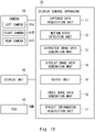
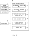
- FIG. 13 is a block diagram of a display control apparatus 40 according to the fourth embodiment.
- the motion state of the vehicle includes a change in the traveling direction of the vehicle
- the motion state information includes traveling direction change information indicating the change in the traveling direction of the vehicle.
- the traveling direction change information includes predicted traveling direction information indicating a traveling direction (a predicted traveling direction) into which the vehicle is predicted to make a change.
- the predicted traveling direction may include a traveling direction into which the vehicle 90 is currently making a change.
- the motion state detection unit 12 may detect a motion state by estimating the predicted traveling direction of the vehicle, based on the position information acquired from the positioning information reception unit and map information.
- the motion state detection unit 12 according to the fourth embodiment supplies the generated motion state information to the extracted image data generation unit 13 and the size assignment unit 18.
- the extracted image data generation unit 13 sets an angle of view in accordance with the change in the traveling direction of the vehicle. For example, upon detection of the change in the traveling direction of the vehicle, the extracted image data generation unit 13 changes the setting of the angle of view of the image (the extracted image) of a region extracted from the captured data relevant to the predicted traveling direction, from the first angle of view to the second angle of view wider than the first angle of view.
- the first angle of view has the magnitude of an initial angle of view set in advance. In this situation, with respect to the angles of view of extracted images extracted from the captured data relevant to the directions different from the predicted traveling direction, the extracted image data generation unit 13 may keep the settings of the angles of view at the first angle of view.
- the extracted image data generation unit 13 extracts an image having the set angle of view from the piece of captured data and generates extracted image data related to an extracted image. As described herein, with respect to each of the pieces of captured data, the extracted image data generation unit 13 generates the extracted image data from the image related to the piece of captured data, by using the angle of view that is set in accordance with the motion state. The extracted image data generation unit 13 supplies the generated extracted image data to the display image data generation unit 14.
- the size assignment unit 18 assigns the image size of a display image corresponding to each of the plurality of pieces of extracted image data, based on a total image size of the display unit 92.
- the "total image size of the display unit 92" denotes a total of the image sizes of the display images that can be displayed in the display part of the display unit 92.
- the "total image size of the display unit 92" denotes a total of the image sizes of such regions.
- a corresponding image size shall be assigned.
- Each of the display images may have a rectangular shape. In that situation, the image size of each of the display images may be expressed as a product of the number of pixels in the width direction corresponding to the dimension in the width direction and the number of pixels in the height direction corresponding to the dimension in the height direction.
- the size assignment unit 18 supplies information about the image size of the display image corresponding to each of the plurality of pieces of extracted image data, to the display image data generation unit 14.
- the display image data generation unit 14 receives the plurality of pieces of extracted image data from the extracted image data generation unit 13 and receives the information about the image size corresponding to each of the plurality of pieces of extracted image data from the size assignment unit 18. With respect to each of the plurality of pieces of extracted image data, the display image data generation unit 14 generates display image data of a display image having the assigned image size. In other words, the display image data generation unit 14 generates the display image data related to the display image by converting the pixel values of the extracted image so as to have the image size corresponding to the extracted image. The display image data generation unit 14 supplies the generated plurality of pieces of display image data to the output unit 15.
- the output unit 15 outputs the display image data corresponding to each of the plurality of pieces of extracted image data to the display unit 92.
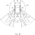
- Fig. 14 is a top view showing the captured ranges of the cameras on the vehicle having the display control apparatus according to the fourth embodiment installed therein.
- the top view of the vehicle 90 shown in Fig. 14 is different from that in Fig. 2 for further having an angle of view B12 of the right camera 91B.
- the solid lines extending radially from the right camera 91B toward the right rear of the vehicle 90 indicate the angle of view B11 and the angle of view B12 wider than the angle of view B11 of an extracted image extracted from the captured images of the right camera 91B.
- the magnitude of the angle of view B11 may be equal to that of the angle of view A11, whereas the magnitude of the angle of view B12 may be equal to that of the angle of view A12.
- the extracted image data generation unit 13 sets the angle of view to the angle of view B11 serving as the first angle of view and, upon detection of a change in the traveling direction to the right direction, changes the setting of the angle of view to the angle of view B12 serving as the second angle of view.
- the extracted image data generation unit 13 sets the angle of view to the angle of view A11 serving as the first angle of view and, upon detection of a change in the traveling direction to the left direction, changes the setting of the angle of view to the angle of view A12 serving as the second angle of view.
- the extracted image data generation unit 13 generates extracted image data of an extracted image related to the angle of view that has been set.
- the pieces of extracted image data include first extracted image data of an extracted image relevant to the scenery on the side of a first direction (the left in the present example) with respect to the vehicle 90 and second extracted image data of an extracted image relevant to the scenery on the side of a second direction (the right in the present example) with respect to the vehicle 90.
- the extracted image data generation unit 13 changes the setting of the angle of view of the extracted image relevant to the scenery on the predicted traveling direction side and generates the extracted image data of the extracted image.
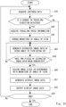
- Fig. 15 is a flowchart of the display control apparatus 40 according to the fourth embodiment.
- the flowchart shown in Fig. 15 indicates an example of processes performed by the display control apparatus 40 when displaying, on the display unit 92, display images relevant to the scenery on the left side and on the right side of the vehicle 90 shown in Fig. 14 (i.e., an example of a two-screen display). In this situation, it is assumed that the angle of view of both of the extracted images is initially set at the first angle of view.
- step S30 the captured data acquisition unit 11 of the display control apparatus 40 acquires captured data from the left camera 91A and from the right camera 91B.
- the captured data acquired from the left camera 91A is captured data relevant to the scenery on the left side of the vehicle 90
- the captured data acquired from the right camera 91B is captured data relevant to the scenery on the right side of the vehicle 90.
- step S31 as a motion state of the vehicle 90, the motion state detection unit 12 of the display control apparatus 40 determines whether or not a change in the traveling direction of the vehicle 90 has been detected.
- the motion state detection unit 12 When it is determined that a change in the traveling direction has been detected (step S31: Yes), the motion state detection unit 12 generates traveling direction change information including predicted traveling direction information. After that, the motion state detection unit 12 supplies the traveling direction change information to the extracted image data generation unit 13 and the size assignment unit 18 and advances the process to step S32.
- step S31: No the motion state detection unit 12 advances the process to step S34.
- step S32 based on the predicted traveling direction information included in the traveling direction change information, the extracted image data generation unit 13 changes the setting of the angle of view of the extracted image extracted from the captured data relevant to the scenery on the predicted traveling direction side, from the first angle of view to the second angle of view. Further, with respect to the extracted image extracted from the captured data relevant to the direction different from the predicted traveling direction, the extracted image data generation unit 13 keeps the setting of the angle of view at the first angle of view. After that, the extracted image data generation unit 13 advances the process to step S34.
- step S34 by using the angles of view set with the extracted images in correspondence with the types of the captured data, the extracted image data generation unit 13 generates extracted image data from the captured data.
- the extracted image data generation unit 13 when a change in the traveling direction has been detected, and the predicted traveling direction is the first direction, the extracted image data generation unit 13 generates first extracted image data of an extracted image related to the angle of view A12 that is wider than the angle of view A11, from the captured data from the left camera 91A. Further, in that situation, the extracted image data generation unit 13 generates second extracted image data of an extracted image related to the angle of view B11, from the captured data from the right camera 91B.
- the extracted image data generation unit 13 when a change in the traveling direction has not been detected, and no predicted traveling direction is acquired, the extracted image data generation unit 13 generates first extracted image data of an extracted image related to the angle of view A11, from the captured data from the left camera 91A. Further, in that situation, the extracted image data generation unit 13 generates second extracted image data of an extracted image related to the angle of view B11, from the captured data from the right camera 91B.
- step S35 the extracted image data generation unit 13 determines whether or not all the pieces of extracted image data have been generated.
- the extracted image data generation unit 13 determines whether or not two pieces of extracted image data have been generated.
- step S35: Yes the extracted image data generation unit 13 advances the process to step S36.
- step S35: No the extracted image data generation unit 13 returns the process to step S34. After that, the extracted image data generation unit 13 supplies all the generated pieces of extracted image data to the display image data generation unit 14.
- step S36 with respect to each of the plurality of pieces of extracted image data, the size assignment unit 18 assigns an image size of the display image corresponding to each of the extracted images, in accordance with the predicted traveling direction indicated by the predicted traveling direction information included in the traveling direction change information. In this situation, in response to the predicted traveling direction being the first direction, the size assignment unit 18 assigns the image sizes so that the number of pixels included in the display image corresponding to the first extracted image data is larger than the number of pixels included in the display image corresponding to the second extracted image data.
- the size assignment unit 18 assigns the image sizes so that the dimension in a primary direction being the width in the transversal direction of a first display image corresponding to the first extracted image data is larger than the dimension in the primary direction of a second display image corresponding to the second extracted image data.
- the first and the second display images are display images corresponding to the extracted images of the first and the second extracted image data, respectively.
- the primary direction may be the width direction or the height direction, and is the width direction in the fourth embodiment.
- the dimension in the primary direction is the dimension of the width represented by one of the sides in the width direction and corresponds to the number of pixels in the width.
- the size assignment unit 18 supplies information about the image size of the display image corresponding to each of the plurality of pieces of extracted image data, to the display image data generation unit 14.
- step S37 with respect to each of the plurality of pieces of extracted image data, the display image data generation unit 14 generates display image data of a display image having a corresponding image size.
- the display image data generation unit 14 generates first display image data of the first display image without performing a pixel conversion process.
- the display image data generation unit 14 generates second display image data of the second display image by compressing the image.
- the display image data generation unit 14 supplies the generated plurality of pieces of display image data to the output unit 15.
- step S38 the output unit 15 of the display control apparatus 40 outputs, to the display unit 92, each of the plurality of pieces of display image data received from the display image data generation unit 14.
- step S39 the display control apparatus 40 determines whether or not the series of processes is to be ended. When it is not determined that the series of processes is to be ended (step S39: No), the display control apparatus 40 returns the process to step S30. When it is determined that the series of processes is to be ended (step S39: Yes), the display control apparatus 40 ends the process.
- the display control apparatus 40 sets the angles of view of the extracted images in accordance with the change in the traveling direction of the vehicle 90.
- the above description uses the example in which the predicted traveling direction is the first direction; however, needless to say, the processes described above are also applicable to processes performed when the predicted traveling direction is the second direction.
- the vehicle 90 keeps traveling straight in the advancing direction, i.e., the example in which no change in the traveling direction is detected, will be referred to as a third example.
- the left camera 91A captures the same image as the image shown in Fig. 4 .
- the extracted image data generation unit 13 sets the angle of view to the angle of view A11 and extracts the region indicated by the border T11, so as to generate first extracted image data from the captured data shown in Fig. 4 .
- the extracted image data generation unit 13 generates second extracted image data of an extracted image related to the angle of view B11, when no change in the traveling direction is detected.
- the size assignment unit 18 assigns an image size of the display image (explained later) with respect to each of the first and the second extracted image data. Further, the display image data generation unit 14 performs a conversion process on the extracted images so that the border is rectangular, while the images each have the assigned image size of the display image.
- Fig. 16 is a drawing showing the third example of the display image displayed on the display unit 92 according to the fourth embodiment.
- Fig. 16 shows a display image P200.
- the display image P200 includes a left display image (the first display image in the present example) P21 and a right display image (the second display image in the present example) P23.
- the left display image P21 is the same image as the left display image P11 in Fig. 5 .
- the right display image P23 is the same image as the right display image P13 in Fig. 5 .
- the display image P200 has a width W. Further, within the display image P200, the left display image P21 is displayed in a region having a width W21. Further, within the display image P200, the right display image P23 is displayed in a region having a width W23. As shown in the present drawing, the sum of the dimensions of the width W21 and the width W23 is equal to the dimension of the width W. The width W21 and the width W23 may have equal dimension.
- the dimensions of the width W21 and the width W23 may be determined in advance so that the left display image P21 and the right display image P23 are generated as images having substantially no distortion, from the first and the second extracted image data of the extracted images having the lens distortion, respectively.
- the size assignment unit 18 assigns a first image size corresponding to the dimension of the width W21 to the first extracted image data and a second image size corresponding to the dimension of the width W23 to the second extracted image data.
- the display image data generation unit 14 has generated the left display image P21 and the right display image P23 having substantially no distortion, based on the image sizes.
- the left camera 91A captures the same image as the image shown in Fig. 6 .
- the extracted image data generation unit 13 sets the angle of view to the angle of view A12 because the predicted traveling direction is the left direction and further extracts the region indicated by the border T12.
- the extracted image data generation unit 13 generates second extracted image data of an extracted image related to the angle of view B11.
- the size assignment unit 18 assigns an image size of the display image (explained later) with respect to each of the first and the second extracted image data. Further, the display image data generation unit 14 performs a conversion process on the extracted images so that the border is rectangular, while the images each have the assigned image size of the display image.
- Fig. 17 is a drawing showing the fourth example of the display image displayed on the display unit 92 according to the fourth embodiment.
- Fig. 17 shows a display image P201.
- the display image P201 is different from the image P200 shown in Fig. 16 for including a left display image P24 and a right display image P26, in place of the left display image P21 and the right display image P23.
- differences from the image P200 will primarily be explained.
- the left display image P24 shown in Fig. 17 was generated from the first extracted image data extracted by the border T12 shown in Fig. 6 . Accordingly, the left display image P24 contains the other vehicle H3 in addition to the other vehicles H1 and H2.
- the width W24 of the region displaying the left display image P24 is larger than the width W21 of the left display image P21 shown in Fig. 16 .
- the size assignment unit 18 determines the dimension of the width W24 so that the left display image P24 becomes an image having substantially no distortion.
- the right display image P26 is generated from an extracted image extracted by the border related to the angle of view B11, which is the same as that in the third example.
- the right display image P26 contains another vehicle H4.
- the width W26 of the region displaying the right display image P26 is smaller than the width W24 of the region displaying the left display image P24.
- the sum of the dimensions of the width W24 and the width W26 is equal to the sum of the dimensions of the width W21 and the width W23 shown in Fig. 16 , i.e., equal to the dimension of the width W.
- the size assignment unit 18 assigns the dimension obtained by subtracting the dimension of the width W24 corresponding to the left display image P24 from the dimension of the width W, as the dimension of the width W26.
- the size assignment unit 18 determines the image size of the display image relevant to the predicted traveling direction and further assigns the image size of the display image relevant to the direction different from the predicted traveling direction based on the difference between the total image size and the determined image size.
- the width W26 of the region displaying the right display image P26 is smaller than the width W23 of the right display image P23 shown in Fig. 16 . Accordingly, when the right display image P23 is compared with the right display image P26, the right display image P26 is relatively shrunk along the width direction.
- the display control apparatus 40 generates the plurality of pieces of extracted image data by using the angles of view set in accordance with the motion state. As a result, without the need to enlarge the area of the display part, it is possible to easily display the information of a wider range with regard to the location which the user wishes to check. Further, based on the motion state, the display control apparatus 40 assigns the image size to each of the plurality of pieces of extracted image data. Consequently, without the need to enlarge the area of the display part, the information about a more important location is displayed relatively large in accordance with the motion state. The user is thus able to more easily check the information about the location which he/she wishes to check. As described herein, the display control apparatus 40 according to the fourth embodiment is able to suitably assist driving of the user, by suitably displaying the images captured by the cameras.
- the display control apparatus 40 sets the angle of view of the extracted image relevant to the direction different from the predicted traveling direction to the first angle of view so as to cause the display unit 92 to display the display image of the extracted image related to the first angle of view.
- the display control apparatus 40 may change the setting of the angle of view of the extracted image relevant to the direction different from the predicted traveling direction to the second angle of view, similarly to the angle of view of the extracted image relevant to the predicted traveling direction.
- step S32 shown in Fig. 15 the extracted image data generation unit 13 sets the angles of view of the extracted images to the second angle of view, regardless of the predicted traveling direction.
- step S34 shown in Fig. 15 upon detection of a change in the traveling direction, the extracted image data generation unit 13 generates first extracted image data of an extracted image related to the angle of view A12. Further, in that situation, the extracted image data generation unit 13 generates second extracted image data of an extracted image related to the angle of view B12. On the contrary, when no change in the traveling direction is detected, the extracted image data generation unit 13 generates first extracted image data of an extracted image related to the angle of view A11. Further, in that situation, the extracted image data generation unit 13 generates second extracted image data of an extracted image related to the angle of view B11.
- FIG. 18 is a drawing showing the fourth example of the display image displayed on the display unit 92 according to a first modified example of the fourth embodiment.
- Fig. 18 shows a display image P202.
- the display image P202 is different from the image P201 shown in Fig. 17 for including a right display image P28 in place of the right display image P26.
- differences from the image P201 will primarily be explained.
- the width W28 of the region displaying the right display image P28 is smaller than the width W24 of the region displaying the left display image P24.
- the sum of the dimensions of the width W24 and the width W28 is equal to the sum of the dimensions of the width W24 and the width W26 shown in Fig. 17 , i.e., equal to the dimension of the width W.
- the size assignment unit 18 assigns, as the dimension of the width W28, the dimension obtained by subtracting the dimension of the width W24 corresponding to the left display image P24 from the dimension of the width W.
- the dimension of the width W28 of the region displaying the right display image P28 is equal to the dimension of the width W26 of the right display image P26 shown in Fig. 17 .
- the right display image P28 is generated from the extracted image extracted by the border related to the angle of view B12 that is wider than the angle of view B11.
- the right display image P28 contains another vehicle H5, in addition to the other vehicle H4 contained in the right display image P26. Accordingly, when the right display image P26 is compared with the right display image P28, the right display image P28 is relatively shrunk along the width direction.
- the display control apparatus 40 may display, in the display part of the display unit 92, a display image relevant to scenery on the rear side, in addition to the display images relevant to the scenery on the left side and on the right side of the vehicle 90 shown in Fig. 14 .
- a second modified example is an example using a three-screen display.
- the extracted image data generated by the extracted image data generation unit 13 further includes third extracted image data relevant to the scenery on the side of a third direction (the rear in the present example) with respect to the vehicle, in addition to the first and the second extracted image data.
- step S30 the captured data acquisition unit 11 of the display control apparatus 40 acquires the captured data from the left camera 91A, the right camera 91B, and the rear camera 91C.
- the extracted image data generation unit 13 changes the setting of the angle of view of the extracted image relevant to the scenery on the predicted traveling direction side, from the first angle of view to the second angle of view, based on the predicted traveling direction information. Further, with respect to the extracted image relevant to the opposite direction from the predicted traveling direction, the extracted image data generation unit 13 keeps the setting of the angle of view at the first angle of view. Also, the extracted image data generation unit 13 keeps the setting of the angle of view of the extracted image relevant to the rear side at C11. After that, the extracted image data generation unit 13 advances the process to step S34.
- the extracted image data generation unit 13 generates third extracted image data of the extracted image related to the angle of view C11 that has been set.
- the extracted image data generation unit 13 determines whether or not three pieces of extracted image data have been generated. When it is determined that all the pieces of extracted image data have been generated, the extracted image data generation unit 13 advances the process to step S36. On the contrary, when the determination result is in the negative, the extracted image data generation unit 13 returns the process to step S34. After that, the extracted image data generation unit 13 supplies the three generated pieces of extracted image data to the display image data generation unit 14.
- the size assignment unit 18 in response to the predicted traveling direction being the first direction, assigs image sizes so that the number of pixels included in the display image corresponding to the first extracted image data is larger than the number of pixels included in each of both of the display images corresponding to the second extracted image data and to the third extracted image data.
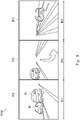
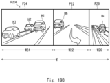
- Fig. 19 presents drawings showing examples of the display image displayed on the display unit 92 according to the second modified example of the fourth embodiment.
- Fig. 19A corresponds to the third example in which no change in the traveling direction is detected.
- Fig. 19B and Fig. 19C each correspond to the fourth example in which a change in the traveling direction is detected. Certain elements corresponding to those in Fig. 16 and Fig. 17 will be referred to by using the same reference characters, and explanations thereof will be omitted.
- Figs. 19A to 19C show display images P203 to P205.
- the dimension of each of the display images P203 to P205 in the width direction is equally W'.
- the display image P203 includes a rear display image (the third display image in the present example) P22, in addition to the left display image P21 and the right display image P23.
- the rear display image P22 is displayed in a region of which the dimension in the width direction is W22. Further, as shown in the present drawing, the sum of the dimensions of W21, W22, and W23 is W'. The dimensions of W21, W22, and W23 may be equal to one another.
- the size assignment unit 18 assigns the dimension of the width W21 to the first extracted image data, the dimension of the width W23 to the second extracted image data, and the dimension of the width W22 to the third extracted image data.
- the display image data generation unit 14 generates the left display image P21, the right display image P23, and the rear display image P22 having substantially no distortion, based on the image sizes corresponding to the dimensions.
- the display image P204 includes the rear display image P22 having the width W22 equal to the dimension shown in Fig. 19A , in addition to the left display image P24 and the right display image P26.
- the size assignment unit 18 assigns the dimension of the width W26 so that the right display image is relatively shrunk along the width direction as compared with the third example (the dimension of the width W26 ⁇ the dimension of the width W23). In contrast, other than those, with respect to the rear display image P22 relevant to the rear side, the size assignment unit 18 assigns the dimension of the width W22 similarly to the third example. As described herein, the size assignment unit 18 may assign the corresponding dimensions in width direction, in accordance with the types of the extracted image data.
- the user of the vehicle 90 is also able to check the situation on the rear side of the vehicle 90, while the same advantageous effects as those in the fourth embodiment are achieved.
- the size assignment unit 18 may assign, to the rear display image, a dimension in the width direction different from the dimension in the width direction in the third example, in accordance with the traveling speed of another vehicle H6 behind the vehicle 90.
- the size assignment unit 18 may assign a dimension in the width direction so that, when the traveling speed of the other vehicle H6 behind the vehicle 90 is lower than a prescribed threshold value, the dimension of the rear display image in the width direction is smaller than that in the third example.
- the display image P205 includes, in place of the right display image P23 and the rear display image P22 in Fig. 19A , a right display image P29 having the width W29 and a rear display image P28 having the width W28.
- the width W28 of the rear display image P28 is smaller than the width W22 of the rear display image P22.
- the width W29 of the right display image P29 is larger than the width W26 of the right display image P26 shown in Fig. 19B .
- the shrinkage rate along the width direction of the right display image P29 with respect to the right display image P23 is smaller than that of the right display image P26.
- the right display image P29 has less image distortion compared to that of the right display image P26. Consequently, the user of the vehicle is able to easily check the situation on the opposite side from the predicted traveling direction of the vehicle, while the same advantageous effects as those of the fourth embodiment are achieved.
- a fifth embodiment of the present invention will be explained, with reference to Figs. 20 and 21 .
- the fifth embodiment is characterized in that the magnitude of the angles of view of the extracted images are set based on the traveling speed of the vehicle 90 in addition to the predicted traveling direction so that the image sizes of the display images are assigned based on the magnitude of the angles of view.
- a display control apparatus 50 according to the fifth embodiment basically has the same configuration and functions as those of the display control apparatus 40 according to the fourth embodiment. In the following sections, differences from the fourth embodiment will primarily be explained.
- a motion state of the vehicle in the fifth embodiment includes a traveling speed of the vehicle in addition to changes in the traveling direction of the vehicle. Further, the extracted image data generation unit 13 according to the fifth embodiment sets the angles of view in accordance with the traveling speed of the vehicle, in addition to changes in the traveling direction of the vehicle. Further, the extracted image data generation unit 13 generates extracted image data of extracted images related to the angles of view that are set based on the predicted traveling direction and the traveling speed.
- the size assignment unit 18 assigns the image size of the display image corresponding to each of the plurality of pieces of extracted image data generated as described above.
- Fig. 20 is a top view showing captured ranges of the camera 91 on the vehicle 90 having the display control apparatus 50 according to the fifth embodiment installed therein.
- the top view of the vehicle 90 shown in Fig. 20 is different from that in Fig. 14 for further having the angle of view A13 of the left camera 91A and an angle of view B13 of the right camera 91B.
- the solid lines extending radially from the left camera 91A toward the left rear of the vehicle 90 indicate the angle of view A11, the angle of view A12 wider than the angle of view A11, and the angle of view A13 wider than the angle of view A12 of an extracted image extracted from the captured images of the left camera 91A.
- the solid lines extending radially from the right camera 91B toward the right rear of the vehicle 90 indicate the angle of view B11, the angle of view B12 wider than the angle of view B11, and the angle of view B13 wider than the angle of view B12 of an extracted image extracted from the captured images of the right camera 91B.
- the extracted image data generation unit 13 sets the angle of view related to the extracted image to the angle of view A11.
- the extracted image data generation unit 13 sets the angle of view related to the extracted image to the angle of view A12.
- the extracted image data generation unit 13 sets the angle of view related to the extracted image to the angle of view A13.
- the angle of view A11 is substituted with the angle of view B11; the angle of view A12 is substituted with the angle of view B12; and the angle of view A13 is substituted with the angle of view B13.
- Fig. 21 is a flowchart of the display control apparatus 50 according to the fifth embodiment.
- the steps shown in Fig. 21 include steps S40 to S46, in place of steps S32 to S36 shown in Fig. 15 .
- Some of the steps that are the same as those in Fig. 15 will be referred to by using the same reference characters, and explanations thereof will be omitted as appropriate.
- step S40 the motion state detection unit 12 detects a change in the traveling direction of the vehicle 90 and, in response to acquisition of the predicted traveling direction information (step S31: Yes), acquires traveling speed information related to the traveling speed of the vehicle.
- the motion state detection unit 12 supplies the predicted traveling direction information and the traveling speed information to the extracted image data generation unit 13.
- step S42 the extracted image data generation unit 13 sets the magnitude of the angle of view of each of the plurality of extracted images of the mutually-different types, based on the predicted traveling direction information and the traveling speed information.
- the extracted image data generation unit 13 generates extracted image data corresponding to each of the plurality of extracted images, by using the angle of view set with respect to each of the plurality of extracted images.
- the extracted image data generation unit 13 when the predicted traveling direction is the first direction while the traveling speed is equal to or higher than a prescribed threshold value, the extracted image data generation unit 13 generates first extracted image data of an extracted image related to the angle of view A12 and second extracted image data of an extracted image related to the angle of view B11.
- the extracted image data generation unit 13 when the predicted traveling direction is the first direction while the traveling speed is lower than the prescribed threshold value, the extracted image data generation unit 13 generates first extracted image data of an extracted image related to the angle of view A13 and second extracted image data of an extracted image related to the angle of view B11.
- the extracted image data generation unit 13 when no change in the traveling direction is detected and no predicted traveling direction is acquired, the extracted image data generation unit 13 generates first extracted image data of an extracted image related to the angle of view A11 and second extracted image data of an extracted image related to the angle of view B11. After that, the extracted image data generation unit 13 supplies the generated plurality of pieces of extracted image data to the display image data generation unit 14.
- Step S45 is the same as step S35.
- the size assignment unit 18 assigns an image size of the display image to each of the plurality of pieces of extracted image data in accordance with the magnitude of the angle of view being set.
- the size assignment unit 18 may assign a first image size of the first display image based on the magnitude of the angle of view corresponding to the first extracted image data relevant to the predicted traveling direction and assign a second image size of the second display image based on the difference between a total image size and the first image size.
- the size assignment unit 18 may determine the image size of the display image corresponding to the second extracted image data.
- the size assignment unit 18 supplies information about the image size of the display image corresponding to each of the plurality of pieces of extracted image data to the display image data generation unit 14 and further advances the process to step S37.
- the display control apparatus 50 assigns the image size to each of the plurality of pieces of extracted image data, based on the magnitude of the angles of view that are set based on the predicted traveling direction and the traveling speed, so that the display images having the image sizes are displayed. Consequently, when the vehicle 90 lowers the traveling speed while approaching a traveling direction change point, the user of the vehicle 90 is able to more easily check the information of a wider range with regard to the location which he/she wishes to check, without the need to enlarge the area of the display part. Consequently, the display control apparatus 50 according to the fifth embodiment is capable of assisting driving of the user more suitably, by suitably displaying the images captured by the cameras.
- FIG. 22 is a block diagram of a display control apparatus according to the sixth embodiment.
- a display control apparatus 60 according to the sixth embodiment includes an index image data generation unit 16, in addition to the configuration of the display control apparatus 50.
- Fig. 23 is a drawing showing an example of a display image displayed on the display unit 92 according to the sixth embodiment.
- an index image is superimposed on the image P201 shown in Fig. 17 .
- an index image G24 is superimposed in an upper part of the left display image P24.
- an index image G26 is superimposed in an upper part of the right display image P26.
- the index image G26 has a shape relatively shrunk along the width direction, as compared to the index image G24. It is thus indicated that the right display image P26 related to the index image G26 is relatively shrunk along the width direction. From this display, the user is able to intuitively understand, by viewing the index image, how the display image related to the index image is distorted.
- the sixth embodiment has thus been explained.
- the display control apparatus 60 according to the sixth embodiment displays the image shrunk along the width direction and also displays the index image indicating that the display image is shrunk and is in the distorted state. Consequently, according to the sixth embodiment, it is possible to provide a display control apparatus and the like capable of suitably displaying the images captured by the cameras.
- a seventh embodiment is characterized in that a display control apparatus detects a motion state of the vehicle based on vehicle information.
- Fig. 24 is a block diagram of a display control apparatus according to the seventh embodiment.
- a display control apparatus 70 according to the seventh embodiment includes a vehicle information acquisition unit 17 in addition to the configuration of the display control apparatus 60.
- Fig. 25 is a flowchart of the display control apparatus 70 according to the seventh embodiment.
- the steps shown in Fig. 25 include step S60 and step S62 in place of step S31 shown in Fig. 21 .
- Some of the steps that are the same as those in Fig. 21 will be referred to by using the same reference characters, and explanations thereof will be omitted as appropriate.
- step S60 the motion state detection unit 12 of the display control apparatus 40 determines whether or not the blinker of the vehicle 90 is on, as a motion state of the vehicle 90.
- the motion state detection unit 12 When it is determined that the blinker of the vehicle 90 is on (step S60: Yes), the motion state detection unit 12 generates predicted traveling direction information. After that, the motion state detection unit 12 supplies the predicted traveling direction information to the extracted image data generation unit 13 and the size assignment unit 18 and further advances the process to step S40.
- step S60: No the motion state detection unit 12 advances the process to step S44.
- step S62 the index image data generation unit 16 generates index image data with respect to each of the plurality of display images. After that, the index image data generation unit 16 supplies the index image data to the output unit 15. Further, in step S38, the output unit 15 outputs each of the plurality of pieces of display image data and the index image data corresponding thereto, to the display unit 92.
- the seventh embodiment has thus been explained.
- the display control apparatus 70 according to the seventh embodiment is capable of setting the angles of view of the extracted images, in accordance with the driven state of the vehicle 90. Further, the display control apparatus 70 according to the seventh embodiment displays the image shrunk along the width direction and also displays the index image indicating that the display image is shrunk and is in the distorted state. Consequently, according to the seventh embodiment, it is possible to provide a display control apparatus and the like capable of suitably displaying the images captured by the cameras.
- the abovementioned program may be supplied to a computer, as being stored by using any of various types of non-transitory computer-readable media.
- the non-transitory computer-readable media include various types of tangible storage media. Examples of the non-transitory computer-readable media include a magnetic recording medium (e.g., a flexible disk, a magnetic tape, or a hard disk drive), a magneto-optical recording medium (e.g., a magneto-optical disk), a CD Read Only Memory (ROM), a CD-R, a CD-R/W, a semiconductor memory (e.g., a mask ROM, a Programmable ROM [PROM]), an Erasable PROM (EPROM), a flash ROM, and a Random Access Memory (RAM).
- a magnetic recording medium e.g., a flexible disk, a magnetic tape, or a hard disk drive
- a magneto-optical recording medium e.g., a magneto-optical disk
- ROM
- the program may be supplied to the computer via any of various types of transitory computer-readable media.
- Examples of the transitory computer-readable media include an electrical signal, an optical signal, and an electromagnetic wave.
- the transitory computer-readable media are able to supply the program to the computer via a wired communication path such as an electrical wire or an optical fiber or via a wireless communication path.
- the display control apparatuses according to the present embodiments are useful for drivers of vehicles to recognize the surrounding environment at the time of driving, for example.
Landscapes
- Engineering & Computer Science (AREA)
- Multimedia (AREA)
- Mechanical Engineering (AREA)
- Signal Processing (AREA)
- Physics & Mathematics (AREA)
- Computer Hardware Design (AREA)
- General Physics & Mathematics (AREA)
- Theoretical Computer Science (AREA)
- Closed-Circuit Television Systems (AREA)
- Controls And Circuits For Display Device (AREA)
Applications Claiming Priority (3)
| Application Number | Priority Date | Filing Date | Title |
|---|---|---|---|
| JP2020057308A JP7459608B2 (ja) | 2020-03-27 | 2020-03-27 | 表示制御装置、表示制御方法およびプログラム |
| JP2020057306A JP7459607B2 (ja) | 2020-03-27 | 2020-03-27 | 表示制御装置、表示制御方法およびプログラム |
| PCT/JP2020/037984 WO2021192373A1 (fr) | 2020-03-27 | 2020-10-07 | Dispositif de commande d'affichage, procédé de commande d'affichage et programme |
Publications (2)
| Publication Number | Publication Date |
|---|---|
| EP4131944A1 true EP4131944A1 (fr) | 2023-02-08 |
| EP4131944A4 EP4131944A4 (fr) | 2023-07-26 |
Family
ID=77891695
Family Applications (1)
| Application Number | Title | Priority Date | Filing Date |
|---|---|---|---|
| EP20928004.9A Pending EP4131944A4 (fr) | 2020-03-27 | 2020-10-07 | Dispositif de commande d'affichage, procédé de commande d'affichage et programme |
Country Status (3)
| Country | Link |
|---|---|
| US (1) | US12101580B2 (fr) |
| EP (1) | EP4131944A4 (fr) |
| WO (1) | WO2021192373A1 (fr) |
Families Citing this family (4)
| Publication number | Priority date | Publication date | Assignee | Title |
|---|---|---|---|---|
| JP7244562B2 (ja) * | 2021-03-23 | 2023-03-22 | 本田技研工業株式会社 | 移動体の制御装置及び制御方法並びに車両 |
| JP7722343B2 (ja) * | 2022-12-08 | 2025-08-13 | トヨタ自動車株式会社 | 映像処理方法 |
| CN115959046A (zh) * | 2022-12-30 | 2023-04-14 | 天瀚科技(吴江)有限公司 | 车用电子后视镜设备及视野随动方法 |
| KR20240111376A (ko) * | 2023-01-09 | 2024-07-17 | 현대자동차주식회사 | Svm 탑뷰 영상처리 방법 및 장치 |
Family Cites Families (17)
| Publication number | Priority date | Publication date | Assignee | Title |
|---|---|---|---|---|
| JP3807330B2 (ja) * | 2002-03-05 | 2006-08-09 | 日産自動車株式会社 | 車両周辺監視装置 |
| JP2005223524A (ja) * | 2004-02-04 | 2005-08-18 | Nissan Motor Co Ltd | 車両周辺監視装置 |
| JP5316550B2 (ja) | 2011-01-05 | 2013-10-16 | 株式会社デンソー | 後方視界支援システム |
| JP2013005032A (ja) * | 2011-06-13 | 2013-01-07 | Alpine Electronics Inc | 車載カメラ姿勢検出装置 |
| JP6020507B2 (ja) * | 2014-04-14 | 2016-11-02 | トヨタ自動車株式会社 | 車両用画像表示装置及び車両用画像表示方法 |
| JP2016048839A (ja) | 2014-08-27 | 2016-04-07 | 株式会社小糸製作所 | 電子制御ユニットおよび車両用映像システム |
| DE102014018040A1 (de) * | 2014-12-05 | 2016-06-09 | Mekra Lang Gmbh & Co. Kg | Sichtsystem |
| JP2016168877A (ja) * | 2015-03-11 | 2016-09-23 | 株式会社東海理化電機製作所 | 車両用視認装置 |
| JP6683451B2 (ja) * | 2015-10-09 | 2020-04-22 | 株式会社東海理化電機製作所 | 車両用視認装置 |
| JP6669019B2 (ja) * | 2016-09-08 | 2020-03-18 | 株式会社Jvcケンウッド | 車両用表示制御装置、車両用表示システム、車両用表示制御方法およびプログラム |
| JP2018074503A (ja) * | 2016-11-02 | 2018-05-10 | 株式会社東海理化電機製作所 | 車両用視認装置及び車両用視認画像表示方法 |
| JP6837931B2 (ja) * | 2017-06-26 | 2021-03-03 | アルパイン株式会社 | 表示制御装置、表示制御方法及びカメラモニタリングシステム |
| JP2019102929A (ja) * | 2017-11-30 | 2019-06-24 | パナソニックIpマネジメント株式会社 | 映像処理システム、映像処理装置及び映像処理方法 |
| JP7147255B2 (ja) * | 2018-05-11 | 2022-10-05 | トヨタ自動車株式会社 | 画像表示装置 |
| JP7148209B2 (ja) | 2018-10-04 | 2022-10-05 | アズビル株式会社 | ワーク検査装置 |
| JP7100257B2 (ja) | 2018-10-04 | 2022-07-13 | 富士通株式会社 | 最適化装置及び最適化装置の制御方法 |
| JP7440235B2 (ja) * | 2019-09-26 | 2024-02-28 | フォルシアクラリオン・エレクトロニクス株式会社 | 表示制御装置、及び表示制御方法 |
-
2020
- 2020-10-07 WO PCT/JP2020/037984 patent/WO2021192373A1/fr not_active Ceased
- 2020-10-07 EP EP20928004.9A patent/EP4131944A4/fr active Pending
-
2022
- 2022-08-29 US US17/898,403 patent/US12101580B2/en active Active
Also Published As
| Publication number | Publication date |
|---|---|
| EP4131944A4 (fr) | 2023-07-26 |
| US12101580B2 (en) | 2024-09-24 |
| US20220408062A1 (en) | 2022-12-22 |
| WO2021192373A1 (fr) | 2021-09-30 |
Similar Documents
| Publication | Publication Date | Title |
|---|---|---|
| EP4131944A1 (fr) | Dispositif de commande d'affichage, procédé de commande d'affichage et programme | |
| EP2424221B1 (fr) | Dispositif d'imagerie, système d'imagerie et procédé d'imagerie | |
| US8305204B2 (en) | Vehicle surrounding confirmation apparatus | |
| US12088950B2 (en) | Image-capturing apparatus, control method, and program | |
| JP2009017020A (ja) | 画像処理装置及び表示画像生成方法 | |
| US8994825B2 (en) | Vehicle rear view camera system and method | |
| CN104081255A (zh) | 用于操作车辆的摄像头组件的方法和摄像头组件 | |
| JP4765649B2 (ja) | 車両用映像処理装置、車両周囲監視システム並びに映像処理方法 | |
| US20060187238A1 (en) | Vehicle-periphery viewing apparatus | |
| CN109429042B (zh) | 一种周围视野监控系统及其盲点视野监控图像提供方法 | |
| US20180288371A1 (en) | Assistance apparatus | |
| JP3847547B2 (ja) | 車両周辺監視支援装置 | |
| JP2005184395A (ja) | 画像処理方法、画像処理システム、画像処理装置および撮影装置 | |
| CN118413752A (zh) | 图像处理系统、可移动设备、图像处理方法和存储介质 | |
| JP2024079872A (ja) | 表示制御装置、表示制御方法およびプログラム | |
| JP2019125894A (ja) | 車載画像処理装置 | |
| US20250071232A1 (en) | Imaging apparatus and imaging system | |
| JP4791222B2 (ja) | 表示制御装置 | |
| US12437378B2 (en) | Image processing device, image processing method, program, and image processing system | |
| US10682956B2 (en) | Image processing device | |
| JP7459607B2 (ja) | 表示制御装置、表示制御方法およびプログラム | |
| JP2007266703A5 (fr) | ||
| US20110080495A1 (en) | Method and camera system for the generation of images for the transmission to an external control unit | |
| KR20120046836A (ko) | 차량용 영상 전처리기 및 이를 이용한 영상 전처리 방법 | |
| WO2019074065A1 (fr) | Dispositif de traitement d'images |
Legal Events
| Date | Code | Title | Description |
|---|---|---|---|
| STAA | Information on the status of an ep patent application or granted ep patent |
Free format text: STATUS: THE INTERNATIONAL PUBLICATION HAS BEEN MADE |
|
| PUAI | Public reference made under article 153(3) epc to a published international application that has entered the european phase |
Free format text: ORIGINAL CODE: 0009012 |
|
| STAA | Information on the status of an ep patent application or granted ep patent |
Free format text: STATUS: REQUEST FOR EXAMINATION WAS MADE |
|
| 17P | Request for examination filed |
Effective date: 20220905 |
|
| AK | Designated contracting states |
Kind code of ref document: A1 Designated state(s): AL AT BE BG CH CY CZ DE DK EE ES FI FR GB GR HR HU IE IS IT LI LT LU LV MC MK MT NL NO PL PT RO RS SE SI SK SM TR |
|
| DAV | Request for validation of the european patent (deleted) | ||
| DAX | Request for extension of the european patent (deleted) | ||
| A4 | Supplementary search report drawn up and despatched |
Effective date: 20230626 |
|
| RIC1 | Information provided on ipc code assigned before grant |
Ipc: B60R 1/22 20220101ALI20230620BHEP Ipc: H04N 7/18 20060101AFI20230620BHEP |
|
| STAA | Information on the status of an ep patent application or granted ep patent |
Free format text: STATUS: EXAMINATION IS IN PROGRESS |
|
| 17Q | First examination report despatched |
Effective date: 20241220 |